

Moving to P4 (Post 14)

Entry posted by Knuckles
624 views
This has repeated information on in part because it is a compilation I did for Scaefour.org's forum. There is plenty of new material though.
First off a quote of the progress so far...
Might be worth making a new thread for this, if so please tell me and I'll post it in a new thread and delete this post after.
Progress report, P4 conversion attempt and a lesson on how to do some mild kit bashing.
Having bent my first Bill Bedford etch the wrong way, I have refrained from Bill's advice of hammering it into a pulp(!) and bent it the opposite way whilst strengthening the wire retaining flaps with some solder.
I have only got a Couple of kits I could try to adapt so I went for the Dapol Cattle Waogon. I don't know how suitable it is for P4 conversion but I have built a few up in the past so am comfortable with the kit - I don't need the instructions for this one so I'm in known territory.
I would like to buy the correct cast axle boxes, leaf springs and all those other 'pipey' bits but I do not know which I need, second to that I'm guessing the S4 stores will be sold out for what I probably need. I looked and it seeems that way, please make suggestions from there or another place so I can get a stock going.
Becasue of the above and the fact I'm an impatient ###### at times I decided to do something that I guess some would see as lunacy! I'm confortable with plastic modeling especially though so I know what I can achieve. I've decided to have a go at cutting the W-Irons out of the 1 peice Dapol moulding whilst retaining the axle-boxes and leaf springs. I know they arn't the best representation available but they are good enough for me, for the time being especially. My challenge is to make a first working P4 wagon so asthetics will have to come later when I know what I'm doing.
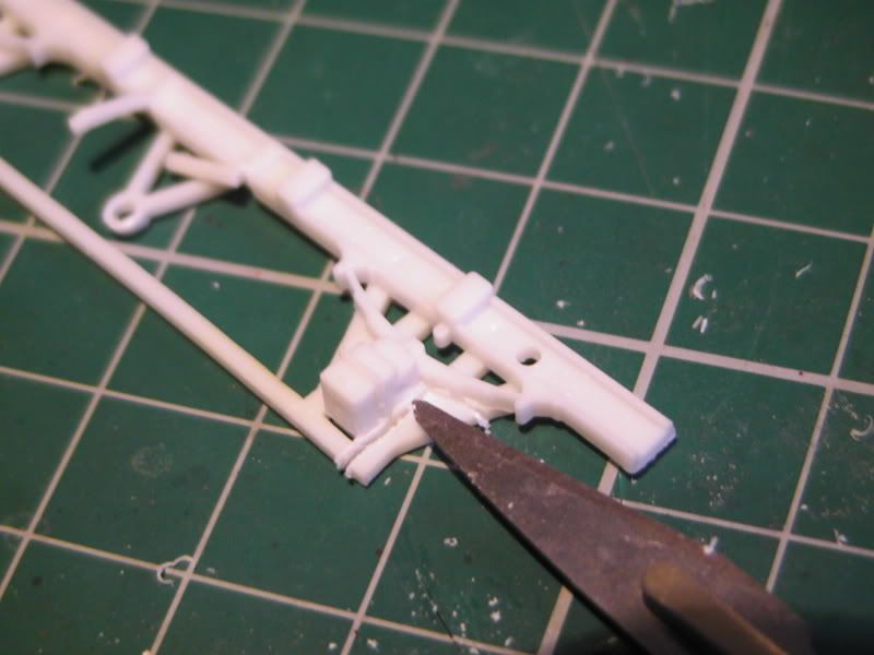
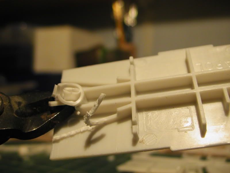
So, first job was to cut the visible W's away from the axle boxes, I used several score lines for this but found it easier after to just clip them out with the Xuron's.
Scored
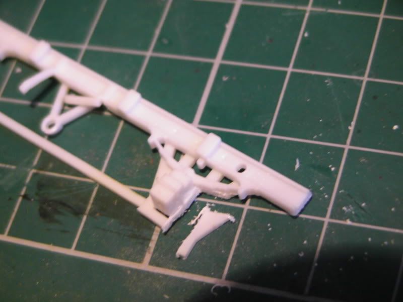
Poped away
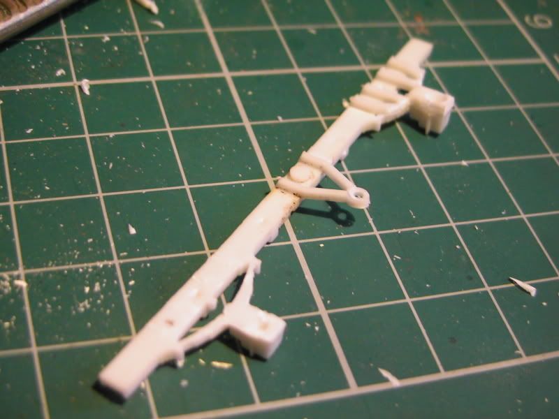
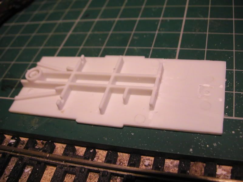
Next stage was to get rid of the rest of the W Irons and make the inside surface flush with the rest of the beam (drag beam? Unsure on a lot of correct terminology)
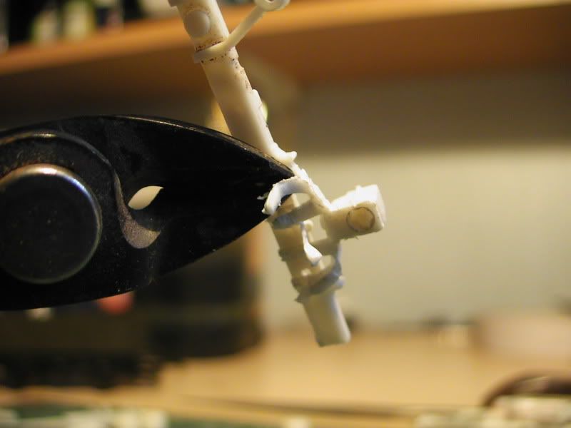
To do this I started to carefully clip away at the W struts.
After that it was a simple matter of knifing the rest away and filing until happy, followed by neatening everything up.
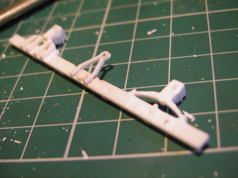
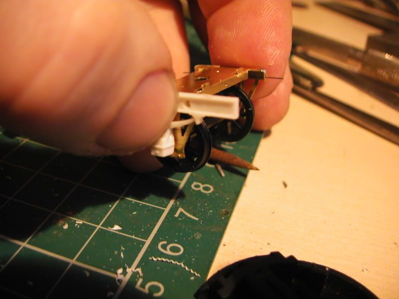
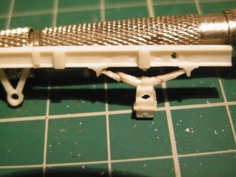
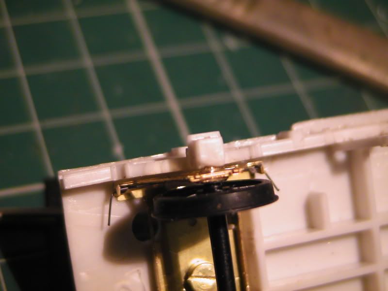
Next stage was to hollow out the axle boxes for the bearing clearence upon spring. two drill holes with the center join hacked away. A mixture of drill action, knife, and various files and a good while later and we have an oval hole.
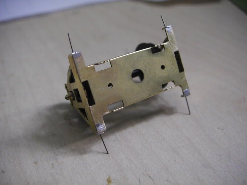
Clearence and fit tests. After these 2 pictures were taken I got the axle box to sit flush with the brass W Iron so happy days, it sprung without getting in the way.
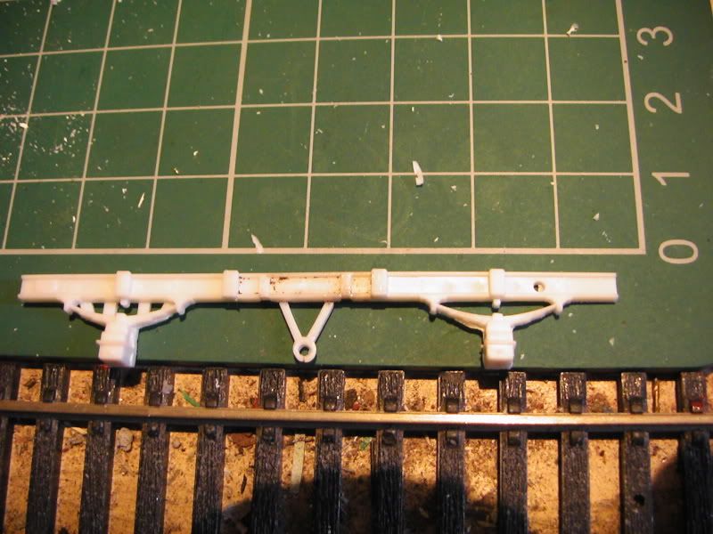
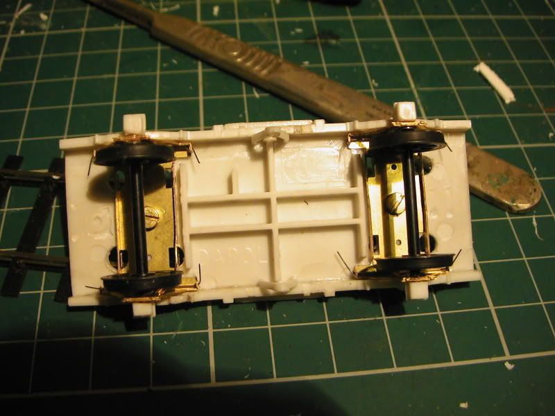
Next thing was to give the main base a few fit tests, supprisingly it seems the etch will fit in nicely once I destroy half of the underside detail, so I used the same method described earlier. Two pictures tell the story.
Repeat for all four.
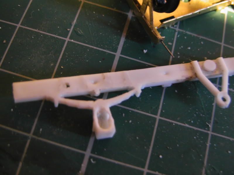
Well there is always one isn't there? I was supprised I got this far after deciding to undertake such a risky operation, however I think I have thus far succeded and have enjoyed it an awful lot. It's been a long time since i've had a decient modelling session where I feel I have made progress. i had to use a bit of scrap to fil the missing bit of leaf spring and glue the other crack. Trying to file this and clip bits away wasn't easy as it broke before I took most of the plastic away, however it now is like the others. Will have to sort those asthetics out after because it looks horrid as I'm sure you will agree. Function is my first priority so it'll be sorted later.
Ugh
That's all for now, please let me know what you think, advice etc.
If you know what type and where I can get decient and correct type sprung bufers for this wagon please let me know, same for the cast or etched components needed for truck conversions.
-------------------------------Next Post--------------------------------
Thanks for your replies.
I've had a fiddle this afternoon and have got a bit further, but as is alot of this I'm sucking it and seeing.
I'm probably doing this all wrong but if I'm doing it wrong then it seems to be working so I do not know!
This looks horrid I know, amazingly crude.
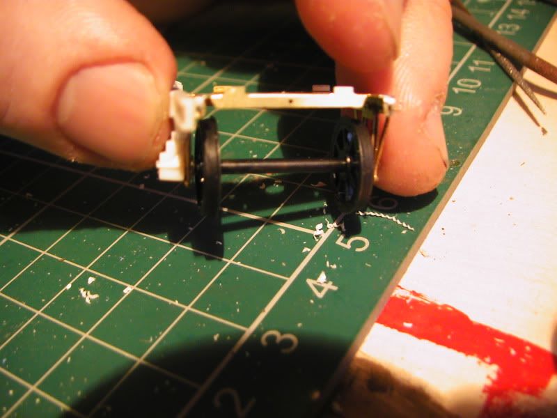
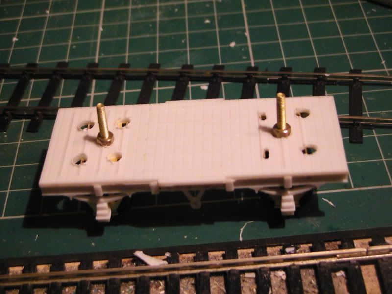
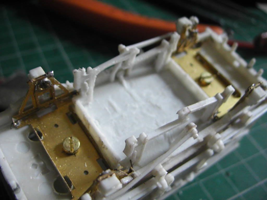
The outer uneven holes are for the tabs in the etch to go through. In hind sight it would probably have been better to file them off but I'm unsure on ride height. I did leave them where they were and packed the etch underneith with plastic card but this was too high a ride height, since popping them through these holes it seems about right, I used my pin vice as a weight and the chassis depressed about half a mm and looks right. I think. Also the screws arn't through the hole evenly and if I was doing a 5 plank wagon this would be unnacceptable but as it's a cattle wagon and a test I'm not too fussed. I'm open to ideas.
This is how it looks before a little wight depression, I think it's fine, looks better when it's dipped a tad. I'm guessing add 25 grams of lead to each etch underneith? (as long as it oens't foul the spring or axle
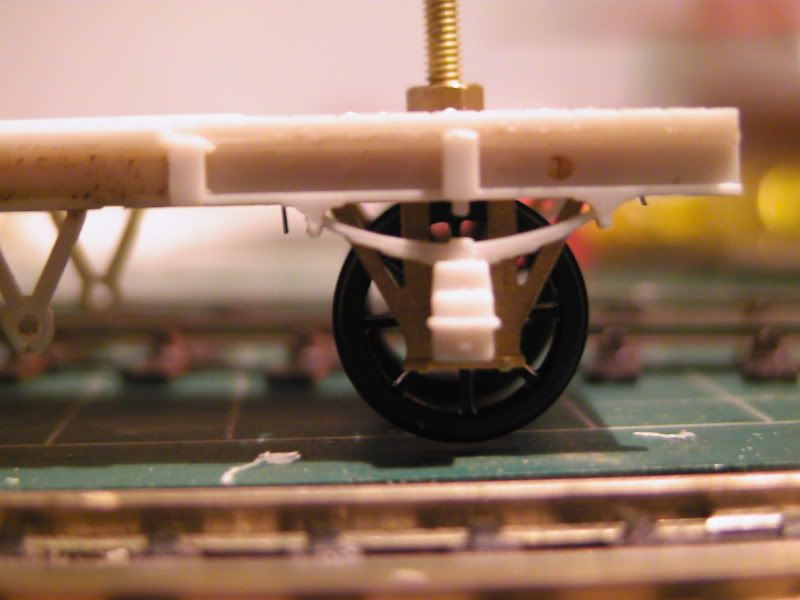
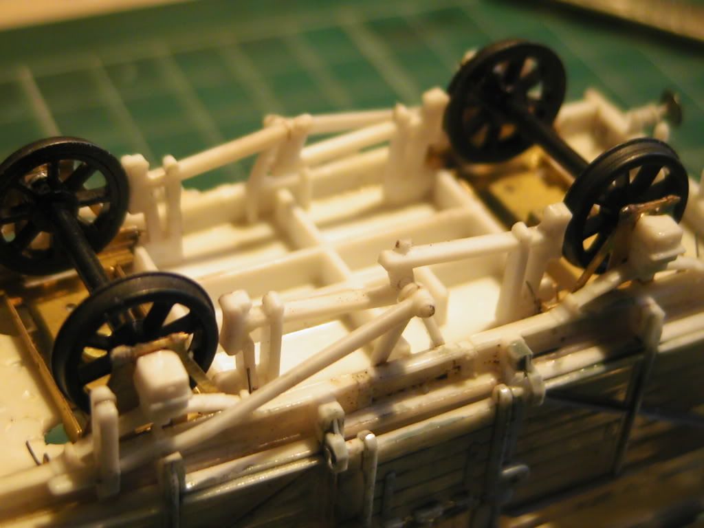
Here the brass W Irons push up to the plastic axles ok but are currently sprung away a tad. This sems to be a matter of messing about more than anything, but is the gaps between everything excessive?
General impression.
I haven't modded the axleboxes or springs or moved them, cut them etc. Might do later but currently think they ok as is.
One thing I really do need to know is how to tell if the wheels are all square to each other etc etc. Currently it's just been a game of tweak and roll. Rolls fine on my straight and bendy bit of track I made but I guess I won't be able to tell until it goes through points. Still waiting on that point blade in the post. I suppose it doesn't help in using a screw in the middle that can pivot either but as I say, I don't really know what I'm doing! it does seem to work ok so far though.
?
-One thing I've noticed since taking thee pics is that one axle seems a tad out on one end compared to everything else, yet it seems to work fine as above. Been tweaking but can't seem to solve the reason or solution.
-----------------------------------Next Post------------------------------------------
I'll probably compile the wagon progress into it's own thread soon. However, please could ye advise me on something?
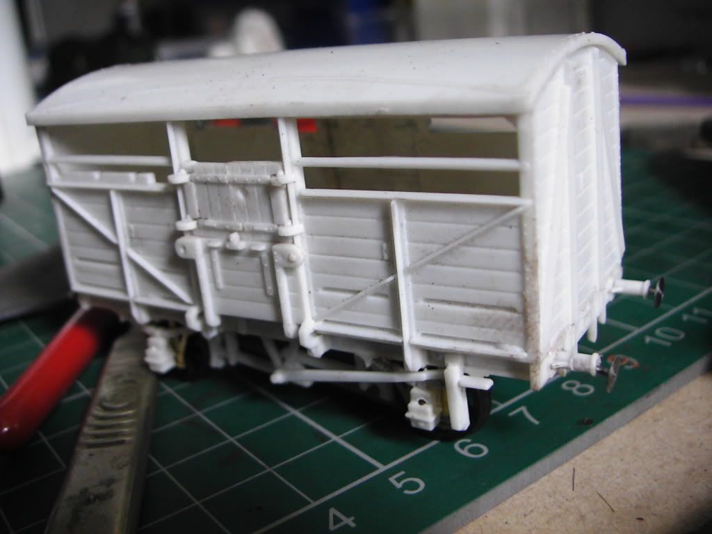
This is where I currently am...
That wonky sprung buffer is the 1st one I showed elsewhere but the other 3 are level, must have been shunted aggressively. I'm not bothering with finer brake gear or anything for this one as it's just a test to see if I can do it. In full Boneheadery I didn't paint the inside, clip those bolts or put weight on the inside. As a result the 'Butanoned' roof is extreemely comfortable where he is!
So how in the world am I supposed to get approximately 25 grams of weight on each axle? Rather than putting it inside I will need to learn how to do it the hard way anyway, otherwise how else are you supposed to represent a train of empties? 5 planks or whatever.
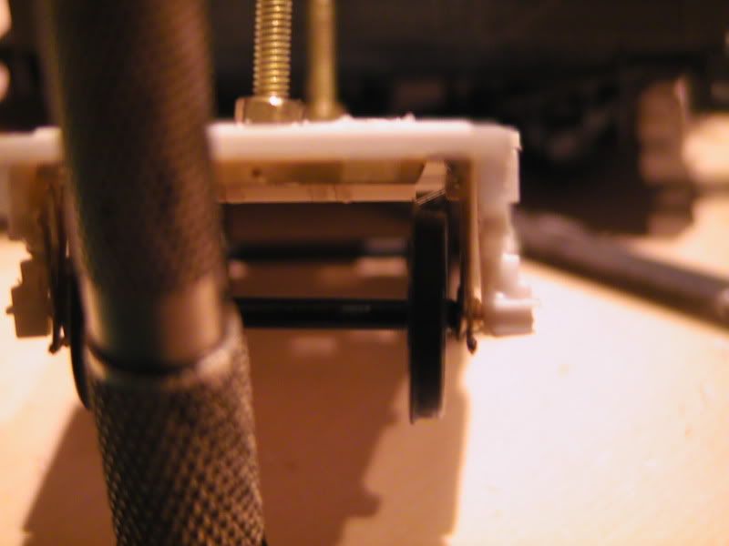
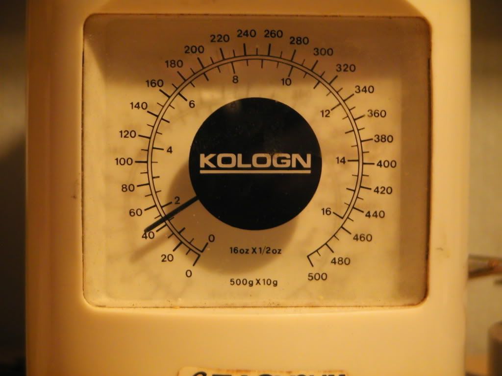
The following fuzzy photo shows some of my roofing lead cut and folded via a vice; it's about the right weight but is immensly thick and more importantly, noticable. Very visual.
I'll probably compile the wagon progress into it's own thread soon. However, please could ye advise me on something?
This is where I currently am...
In full Boneheadery I didn't paint the inside, clip those bolts or put weight on the inside. 'As a result the Butanoned' rood is extreemely comfortable where he is!
So how in the world am I supposed to get approximately 25 grams of weight on each axle? Rather than putting it inside I will need to learn how to do it the hard way anyway, otherwise how else are you supposed to represent a train of empties? 5 planks or whatever.
The following fuzzy photo shows some of my roofing lead cut and folded via a vice; it's about the right weight but is immensly thick and more importantly, noticable. Very visual.
Um. Ahee. Any ideas? :shock:


To which a few people kindly replied helping loads. Thanks. 
One reply in particular I found very helpful. Pictures always help too.
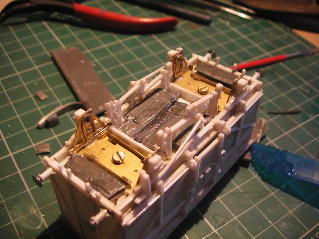
This is one of our resin 7 tonners from Burntisland' date=' and you can see how the lead weight is fitted in. The thickness of the lead is a fraction less than the depth of the solebars (Squeeze it a bit harder in the vice if needs be)
You just need to cut the lead to fit the available spaces and fit it carefully to avoid fouling any moving parts. And don't use an adhesive that will dissolve the wagon floor -- I use Araldite rapid. You could probably remove the crossmembers under the floor.
The weight of that verra wee wagon, incidentally, is 32.8 gm; one of our group has managed 35 gm, but that's pushing things. The 25 gm per axle is just a suggestion -- what is important is reasonably consistent weights throughout the train.
Allan F
[attachment=0']Resin underside.jpg[/attachment]
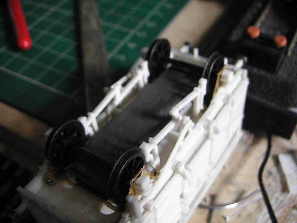
Thus...
Before (complete with yellow lamp lighting!)
After Xuron and mini drill abuse
Aaaand...
"Wont sum led mayte? ayve got loads younz"
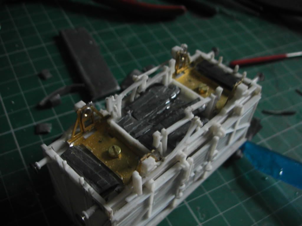
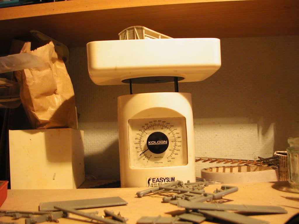
45 grams, I was aiming for 50 so Happy days.  I used 2 part epoxy resin glue.
All that's needed now is to add 3 link couplings, pipes and paint. I am seriously thinking of using Dingham couplers because they to my mind look the part and I think they operate well. Apparently they are compatible with 3-link, Instanter and screw link so I might be able to have a choice. I did seriously think about using Alex Jackson couplings but I think in all honesty they have gone 'too far' with the attempt to have an unobtrusive coupling and as a result it looks a bit like the stock is being propelled by ghosts. For these P4 experiments (or am I a convert yet?? probably, where is that line?) I want to build a small wagon fleet up with 3 links. Tony Wright of BRM said tension lock couplers look like "Obese snowloughs", I'm inclined to agree with him! :x
5 Comments
Recommended Comments
Create an account or sign in to comment
You need to be a member in order to leave a comment
Create an account
Sign up for a new account in our community. It's easy!
Register a new accountSign in
Already have an account? Sign in here.
Sign In Now