- Popular Post


Ian Smith
-
Posts
1,402 -
Joined
-
Last visited
-
Days Won
1
Content Type
Profiles
Forums
Blogs
Gallery
Events
Exhibition Layout Details
Store
Posts posted by Ian Smith
-
-
Bendy ply for baseboard tops is your friend here, then you can feed it through the printer and print directly onto it (works best on April the first though)

-
 1
1
-
 3
3
-
-
- Popular Post
- Popular Post
517 progress...
Yesterday I started adding some weight to the model - principally so that I could move onto the next elements of construction! The reason being that I wanted to fill the smokebox with lead before I fitted the smokebox door, as without the door on I could ensure that the movement of the worm would not be interfered with by any weight added.

A view into the smokebox to show how much room there is above the worm within the smokebox and front part of the boiler.
A more top down view showing the amount of room for weight in front of the worm (about 2.5mm between end of worm and back of door).
A piece of 2mm thick lead sheet was rolled around a 4mm drill shank and cut to size so that it filled the top part of the boiler/smokebox above the worm and motor shaft in the form of a bit more than a U profile, further pieces of lead were then cut to fill the space between the legs of the U but still clear the worm. Using a spare bit of boiler tube, I then cast a lead plug to fit in the end of the smokebox. All of this was fixed in place with superglue.
The smokebox door was completed with small strips of 0.006" for the hinges (the ends wrapped around a bit of guitar string for the hinge bar), and soldered in place on the face of the door. A piece of 0.3mm nickel silver wire was soldered into the hole in the door face before a pair of 2mm Association etched handrail knobs were soldered on to represent the door dart handles. The wire was cut and filed back to the handles to leave a reasonable representation of the dished smokebox door with the handles.
The completed smokebox door assembly with the etched handrail knob door handles.
With the weight secure, the smokebox door was then also secured in place with glue, I actually used Loctite thread retainer rather than superglue as I needed the freedom to allow the door to be rotated to ensure that the hinges were horizontal!
The current state of play - it may be noticed that I have also added the small steps on the smokebox sides, and the handrail knobs on the smokebox and boiler and finally fitted the handrails by the cab entrance.
Next on the list is to make the combined smokebox front handrail knob-come-lamp socket, then the smokebox/boiler handrail can be bent up and fitted. Then it's that final list of small bits and pieces that need making and fitting to complete her.
Finally, a short video of her "running" using a home-made PP3 battery controller - the controller doesn't quite go down to zero volts, so with her wheels in the air she never actually stops, but hopefully it shows that she runs quite nicely!
Thanks for looking,
Ian
-
 22
22
-
 9
9
-
- Popular Post
- Popular Post
Not a lot of time for modelling towards the end of the week, so progress on the 517 has slowed a bit. However, I did manage to fit the buffer housings to the buffer beams and sort out the chimney.
The turned buffer housings were soldered onto a piece of 0.006" nickel silver sheet to represent the back plate of the housing. The 0.8mm hole in each housing was run through to pierce the sheet before each housing was separated and the back plate squared up and filed down to size. It was then a simple job to solder each housing in place on the buffer beam, holding it in the correct place with the aid of the shank of the 0.8mm drill running down the housing and into the corresponding hole in the beam.
The Smokebox/Boiler/Firebox assembly has also been soldered in place.
Rather than make a new chimney, I decided to put a piercing saw through the mark 2 version, to remove a little height. A bit of filing and a short length of 1.5mm brass rod up the hole in the bottom of the chimney to ensure the two parts were held in registration allowed the top and bottom to be reunited with a flash of solder. Now happy with the size of the reduced chimney I've soldered it in place on the smokebox.
Finally, I've made and fitted the 3 lamp sockets that were bolted to the footplate above the buffer beam.
The photo below shows the current state of play :
I'm starting to get to a place where I need to make a list of all the sundry items that need to be made and fitted to finish her off, but before I do I will turn up the Safety Valve cover and finish the smokebox door!
Thanks for looking
Ian
-
17
-
 1
1
-
11
-
Looks to me like a cross strapping - on the inside can be seen a “normal” strap running wagon end bottom to door top, but also evident is the curved top end of a strap at wagon end, on the near solebar the bottom end of such a strap can be seen bolted to solebar below door.
Ian
-
4
-
-
12 hours ago, Ian Morgan said:
Nit-picking, but actually more like Mercury capsules than Apollo ones.

Ian,
You’re quite right of course, getting my space programs mixed up

-
- Popular Post
- Popular Post
517 progress ...
Todays little exercise has been turning...
A set of buffer housings have been turned from brass bar, they will be soldered onto a piece of 0.004" nickel silver which in turn will be cut and filed around the base of the turnings to represent the back plate of the casting which was bolted to the buffer beams. At the minute they look rather like the splash-down capsule of the NASA Apollo rockets

A set of buffer housings (or NASA Apollo splash-down capsules). The wire allows them to be kept together, so that if one is lost they all are! The wire was also used to stop them from flying off into the ether when they were parted off - the wire was poked into the buffer ram hole while the parting off operation was completed.To give an idea of the size of these, the height of each is about 0.090" (2.25mm).
Similarly, I have also turned a new chimney from phosphor bronze, and a dome from more brass bar (I've still got the safety valve cover to make). The other thing I've done over the last couple of days is to make and fit the springs that lie behind the splashers. These were fretted and filed from a double thickness of 0.015" brass sheet before being separated. Once the fiddly job of soldering them in place behind the splashers was accomplished, the bit hidden by the splashers was carefully filed away so that they didn't catch on the wheels. Annoyingly, one of the ends of the springs came adrift right at the end of this operation, and once found on the floor the even more fiddly job of soldering a pretty minute piece back on ensued!!

The current state of play, showing the new chimney and the dome. The front driver spring can also be seen behind the splasher. This photo reminds me of the other thing I've done - fitted the handrails on the front of the tanks. They jury is currently out on the new chimney - having compared the model to the prototype in an earlier posting I felt that the original was a bit too squat, I think this one might be a tad too tall - I've made it a scale 4'0" tall as scaling from the photo seemed to indicate that was about how tall it was.
Earlier today, I also repainted the chassis as that was pretty scarred from handling and stripping and rebuilding a week or two ago.
Thanks for looking
Ian
-
7
-
15
-
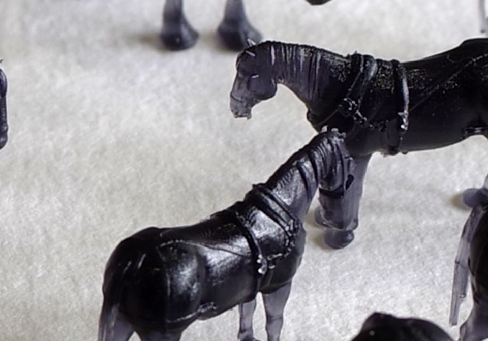
6 hours ago, CF MRC said:
Bloodstock on CF will soon be improving...
So we shall need some shovels and wheelbarrows...
TimTim,
Really nice to see some horses in 2mm scale that actually look like horses!!
I really must take a micro chisel and low melt solder to the white metal lumps in my collection.
Ian
-
2
-
2
-
-
- Popular Post
- Popular Post
The 517 Bunker sub-assembly has now been completed ...
The handrails are 0.009" guitar nickel plated string, and for the first time I have used the 2mm Association etched handrail knobs rather than my usual twisted wire stanchions. I must say that I will use these on all future projects!!
I have fretted/filed out a representation of the reversing lever from 0.015" brass which has also been adde to the cab floor, and the strengthening ribs for the bunker back sheet have been added from 0.006" nickel silver. To allow some form of integrity to be maintained in these (and to save my sanity), I simply filed out a squared off U shape with the gap between the legs of the U being the distance apart of the strengthening ribs. The bit of material where the legs meet the bottom was thinned with a fine 3-square file to allow the legs to be bent 90 degrees to the base more easily. It was then a fairly simple operation to manoeuvre the ribs into position as it was soldered in place. As hopefully can be seen in the photo below the ribs were made and positioned so that I could file the tops of the ribs flush with the top of the bunker once this part was secure.
The bunker assembly with the reversing lever in place (I must admit that it looks pretty crude in this blow-up, but looks acceptable in real life). Hopefully, the method of forming the bunker back sheet ribs can also be seen (obviously a lot of it will be hidden by the coal eventually).
The final items added to complete the bunker were the sand boxes and brake standard. I had made all of these a few days ago, the sandboxes being blocks of brass filed down from a bit of 3mm square brass bar. The tops were drilled to accept the pegs of some little turned lids. The brake standard is another simple turning, the handle being added from phosphor bronze wire soldered into a little trough filed across the top of the standard, once secure the wire was bent to form the upright handle and excess cut off. I elected to superglue these items in place for fear of causing damage while wielding the hot stick about - I had to re-attach the top lamp socket after fitting the strengthening ribs as that had become detached!
A couple of photos of the completed bunker assembly (well complete apart from a bit of cleaning up with a scraper!!)
Thanks for looking.
Ian
-
12
-
16
-
- Popular Post
- Popular Post
Progress on the 517 ...
Firstly, the washout plugs have been added to the firebox. These are simply bits of 0.4mm copper wire with about 1mm of the end squashed square in a pair of pliers, and the end made good with a fine no. 6 cut file.
0.4mm holes were drilled in the side of the firebox, and the outside face opened out to 0.8mm (leaving a 0.4mm hole in the bottom of the 0.8mm depression). The end of the wire was poked in and then drawn through from the inside until the squared off section was flush with the outside of the firebox.
Cruel enlargements of the finished washout plugs.
The plugs are tight in their holes, but have been secured with a bit of superglue - on one side I initially tried to solder them in place but the solder wicked through and filled the holes on the outside!! Oh how I laughed!! (I actually did, as I couldn't believe that I'd been so daft as to try, as I knew that it would happen!) More heat was applied, the plugs pushed out and the holes made good again with the relevant drills allowed common sense to prevail and use glue instead.
I've also been busy with the bunker, the bunker back being soldered to the cab floor, a piece of 0.010" cut for the bunker front and similarly soldered in place. Additionally, a length of 5 amp fuse wire has been soldered along the top extremities of the bunker sides and back to represent the beading. Holes for the handrail knobs have been drilled in the bunker side sheets too.
Todays task has been to address the rear of the bunker, the lamp sockets. A length of 1mm square brass bar was filed down to be 0.8mm square, this was then placed in the lathe and the end couple of mm turned down to 0.4mm diameter. The work piece was then transferred to the vice where the excess bar was sawn off, and the embryonic lamp socket filed back to leave me with a 0.8mm cube on a stalk. The cube was then cross-drilled 0.3mm (for the lamp spigot) :
A set of lamp sockets for the rear of the bunker - I only needed 4 but made a couple of spares in case the carpet monster was filing peckish.
Four holes were drilled in the rear bunker sheet for the stalks of the lamp sockets. Initially, these were drilled 0.4mm but had to be further broached until the stalks fitted snuggly. A little bit of wire was bent up to hold the sockets a consistent distance (and at the correct orientation) from the bunker sheet while they were soldered in place. The final task while I was at it was to bend up some tool brackets from narrow strips of 0.004" which were soldered in place on the rear of the bunker.
The lamp sockets and tool brackets in place on the rear of the bunker. I might give each one a wipe with a fine file to further reduce their size, and the top of the furthest tool bracket could certainly do with a wipe or two just to make it more compatible with its fellow.
A final shot with everything just plonked together on the chassis to show the current state of play.
Thanks for looking.
Ian
-
14
-
13
-
5 hours ago, Mikkel said:
The model is looking superb Ian.
I assume that, afterwards, you'll be doing those 5-6 Siphons in the background?
") 1 hour ago, bgman said:
1 hour ago, bgman said:It'd be rude not too !
Hmmm, 5 or 6 siphons or another loco? Decisions, decisions

Then again, there’s that train of clerestory bogie stock that I keep promising myself that I ought to get on with!
-
5
-
1
-
-
On 28/04/2021 at 11:22, richbrummitt said:
How has the fit turned out wrt. the drive on the front driver being visible from the side, especially with having to reduce the diameter of the worm gear with the result that the motor shaft sits lower than originally intended?
Rich,
In short the interior gubbins is completely hidden! I was careful to only remove what I needed to to clear the worm and motor shaft (the Tramfabriek 6x15 motor is completely hidden within the tanks).
Underside of the boiler assembly to illustrate the areas removed to a) allow it to sit snuggly on top of the tanks and b) to clear the motor shaft and the worm. The red staining within the boiler tube is evidence of the heat applied when I silver soldered the boiler barrel into the rebate in the firebox.
Side on view that shows that the motor shaft is actually a little higher than the bottom of the boiler, and the worm is hidden behind the splashers. When I have made and fitted the springs that sit behind the splashers the end "shackles" will probably even hide what can be seen of the cutout below the boiler.
Just realised that that low down side on shot also gives away my secret - an outside pick-up spring that plugs into the side of my solid chassis. The plug is usually a bit of 0.5mm phosphor bronze but on this loco it's a piece of 1mm brass wire (in my haste I'd drilled the holes too big by picking up the wrong sized drill! - I had just drilled 12BA tapping holes). On this side it only goes in 1mm as this is the 1mm strip side of the chassis. The spring itself is some fine phosphor bronze wire which wraps around the plug once and is soldered to it. The spring wire is cut to reach the outer extremities of the flange so that there is no chance of it ever catching on the spokes, obviously it bears on the top of the axle like any normal "Simpson" spring. Looking at this photo on the computer screen I've also just realised that I've put the coupling rod on upside down on the side - that will be addressed when I next warm up my hot stick.
Ian
-
12
-
1
-
 1
1
-
1
-
-
- Popular Post
- Popular Post
A little more progress on the 517 was made yesterday ...
The bottom of the firebox and boiler assembly were attacked with a piercing saw and various files to remove the area above the tanks. Similarly, the bottom of the boiler and rear of the smokebox (and saddle) were removed to clear the motor shaft and worm. Once I was happy with the fit of the boiler assembly over the tanks, I decided that since the fly-cutter was set up for the smokebox diameter (from making the saddle) it would make sense to knock up the chimney! So a happy hour or so was spent whittling away at a length of phosphor bronze bar to produce the chimney. I still need to open out the top of the chimney and file it down a little, but trying to hold it while doing that hurts the fingers so I will solder it in place and try to do it in situ.
A couple of photos with everything just plonked in place for the time being :
Now that I can see where the smokebox comes, I have taken a fine file to the back of the splashers to thin them down a fair bit because I need to put some springs in the gap between splasher and boiler/smokebox before the the boiler assembly is permanently fixed in place.
Also to be done before the boiler assembly is fixed in place will be the drilling of holes in the firebox for the washout plugs and also holes for the handrail knobs.
I feel that she is starting to look like a 517 now, hopefully eventually she will look a bit like this :
Thanks for looking
Ian
-
12
-
12
-
- Popular Post
- Popular Post
A little more progress on the 517...
The Bunker has been has been formed from a strip of 0.008" nickel silver, cut over-long, bent as I did with the tanks, and then the sides cut and filed back to length before finally filing the distinctive "chair back" profile. A strip of 1mm thick brass has also been cut and filed to provide a cab floor, the bunker fits around the back of this floor, which has also been drilled and tapped 14BA to provide the fixing for the chassis/body bolt (this is the way I have built all of my tank engines - I find it a useful dodge to have the bunker as a separate component as it makes painting / lining easier and allows me access into the cab for when I decide to fir a back-head).
The Bunker and cab floor.
The Bunker and cab floor in place (albeit as a dry run - nothing has been soldered together yet).
I've also made a bit of a start on the Boiler assembly. The main boiler is a piece of brass tube that I turned down a little, a further piece of the same tube has been cut for the Smokebox, but to get it to fit around the main boiler, a slit has been cut across the bottom, allowing it to opened out as it is forced over the end of the boiler. The raised Firebox was turned down from a suitable piece of brass bar, and was bored out to the same internal diameter as the main boiler, with a 3mm section of the boring at the boiler end opened out to allow the boiler tube to seat inside. The 3 elements were then soldered together to form a Firebox/Boiler/Smokebox component.
Todays task has been a little more machining - the Smokebox Saddle was formed by fly-cutting a seating for the base of the smokebox tube in a length of 2mm thick brass bar. Once done, the saddle was separated, filed to width and a section on the end filed to shape to represent the valve chest cover. Todays other task was to turn the smokebox front/door - a piece of 0.028" nickel silver was soldered onto the end of an arbour, turned down to size so that it fitted snuggly in a rebate bored into the end of the smokebox, then gravers were employed to turn the distinctive door ring and dished profile of the door.
The Smokebox/Boiler/Firebox component after soldering the 3 elements together (the rebate for the smokebox door can clearly be seen in the end of the smokebox).
The smokebox saddle and smokebox door. The gap in the smokebox wrapper can be seen in this photo where the piece of tube was slit to allow it to fit over the boiler tube.
The boiler components combined for photographic effect. Unfortunately, I hadn't realised that the smokebox door had fallen out of place when I took the photo - it does actually fit snuggly in the rebate in the end of the smokebox!
Hopefully, I will get the smokebox door furniture fabricated and in place tomorrow, then the parts can be soldered together so that I can attack the lower half of the boiler and firebox with a saw and files to get it to fit in place over the tanks.
Thanks for looking.
Ian
-
14
-
18
-
As promised, a link to part of my Modbury thread, showing the last coach I painted. The coach itself is an S6 All Third which I have finished with Oil lamps (an earlier one in the same rake has Gas lamps.
A couple of pages earlier in the thread I described how I paint the coaches, here :
Hope it is helpful.
Ian
-
1
-
-
C19 is coming along very nicely, when I paint my coaches in this livery (albeit in 2mm scale), I do the mouldings with a 0.1mm nibbed Rotring pen with their own black ink. There is always re-touching to do on panels which I tend to do with thinned paint and small brush and copious use of capillary action.
As I’m writing this response on my mobile I can’t link to suitable entries in my RMweb Modbury thread here, but if I remember later I’ll update this entry with a suitable link.
Keep up the good work.
Ian
-
 1
1
-
-
1 hour ago, Edwardian said:
Thanks, Ian, that's a great photograph.
I am trying to curate this conversation as neutrally as possible, because the only thing I'm sure of is that we cannot be sure of these points. Hence I tried to sum this issue up as representing plausible alternatives. My personal view is that I see a logic in consistent GW practice, apparently from the days of all-over brown in the 1850s, through to the all-over grey of the 1904 livery. I try to judge each image or other piece of evidence as objectively as I can, nevertheless.
I would venture the following:
- None of these seem to be long-bonnet minks. As I wouldn't put the earliest likely possible shift to grey earlier than 1898, I think it very likely that we are looking at 3 red minks.
- Like you, I cannot see any difference in tone. To me this is not definitive proof that same tone indicates same colour - weathered to an even finished might be an explanation - but it probably makes it more likely to be the case. Certainly there is nothing in this photograph to evidence black painted areas. As neutrally as possible I would say this picture offers no positive evidence for black painted areas and tends to support all-over red.
- Bear in mind, however, that the rooves probably started off white, which has blackened to grey, leaving a tone not very much difference from the body red, suggesting, perhaps, the limitations of judging colour from black and white tone. That said, the uniformity of tone across a single plane of view between body and chassis and running gear is remarkable.
- The brake van we agree will be grey. Do we think it an all-over grey? If so, that would speak for a consistency of practice.
James,
I think that what has been offered by yourself and others is very definitely a neutral viewpoint. Personally, I have no axe to grind one way or another, as I don't think that the evidence is there to fully support or fully refute any argument. As your previous set of images shows there is "evidence" that can be offered to support almost any argument, including that of black ironwork with red (or possibly even grey) woodwork! Interestingly (to me at least) is the 4 planked 632 with the cast plates, as in looking for the accident photo I came upon that one and my immediate thought was that the woodwork does look a different colour to the ironwork (it's certainly a different tone, but it is also glossy rather than the matt of the woodwork which potentially confuses the issue further).
I have also revisited the images of wagons in the Broad Gauge dump which one would imagine are all red wagons, and again to my eyes I do not see a vastly different tone between the body work and the underframe to indicate that the lower parts of the wagons were in fact a different colour. Obviously the wagons in those images are all at the end of their lives so are well weathered, by that I mean that as the demise of the Broad Gauge was on the cards for a while before it happened I cannot believe that any of the stock would have been repainted within 2 or 3 years (or probably more) of 1892.
Although there will probably never be any new evidence to come to light, I do find these discussions very interesting and enlightening.
Ian
-
1
-
1
-
-
13 hours ago, tapdieuk said:
A half dozen P O wagons.
2 diffrent wagon bodies to give a bit of varation. The older mouldings needing some internal details.
A bit tedious at times, but progress is being made.
I assume that one of the half dozen is lying to the right of the underframe etches and has been printed in (very) clear resin
Ian
-
In defence of my view of red wagons being red over all, one of the images that I used to come to that conclusion is offered below. The image comes from the Outside Brake Van article by John Lewis in a British Railway Journal (No. 17).
As can be seen it is of an accident, and interestingly one of the Iron Minks is lying on its side, meaning that body side, solebar and brake gear handle are all in the same plane and exposed to the sunlight in a similar way (rather than being cast in shadow by the over-hanging body). In my view the tone of the whole wagon seems to indicate that there is no discernible colour difference between the body and the solebar or axleboxes or the brake lever. The liveries of the (visible) Iron Minks is the 5" G.W.R, and the caption estimates a time period 1897-1903, so I've reasonably assumed that the wagons would all be in red livery (except the Brake Van of course).
Thoughts???
Ian
-
3
-
3
-
-
Aah the lid on the old can of worms is being prised off again
Personally, I have adopted a grey date somewhat before 1904, in that the wagons I’ve applied cast plates to are in grey livery. I’ve also gone with an all over red livery, ie everything below the solebar is also red.
I have no evidence for any of the decisions I’ve taken though! The first open wagon I fitted the plates to was red but I felt it didn’t look right so repainted it grey (I have gone with white lettering on a grey background for my plates), and I adopted the all over red simply because the later livery was an all over grey.
Ian
-
1
-
1
-
-
25 minutes ago, Royal42 said:
Hello all, I am in need of advice please. I am about to order a turnout set, plus some bullhead sleepers and loco wheels, for my Birmingham New Street diorama. My problem is that I do not understand how to identify the components of what I need. Can anyone help with these queries?
a. there appears to be two sizes of sleepers, 8ft 6in and 9ft 0in, which size would I need for the ex-LMS/LNWR up to 1964?
b. Looking at the available locomotive wheels available, Mk.4 and Mk.5 etc., how can I identify what locos they would fit?
c. how can I identify and work out what radius turnout I need? The turnouts on my layout appear to be fairly gentle but that isn't a recognised term when ordering these. Any advice here please?
The items I want to buy will be my first test/taster to building the rest of this layout and so would like to order the correct bits.
cheers,
MikeMike,
There are many other members who are much more qualified to answer your queries, but ...
a. 9’0” sleepers were a pre-grouping size (pre 1923), so by 1964 in a main line situation like Brum New St I would expect 8’6” sleepers - I have no idea when concrete sleepers were introduced so they may be needed (anyone who knows me and my interest will understand that final comment).
b. The loco wheels supplied by the Association are “generic” so may not be entirely suitable for a specific class of locomotive (as a group we don’t generally concern ourselves too much about that although we do have H section spoked or Bullied wheels for certain circumstances). The older Mk4 wheels are cast brass, the new Mk5 being derived from 3D printing.
c. I can’t really advise on the Association turnout kits as I have never used them (again anyone who knows me will know why)
hopefully someone with better knowledge will be along soon.
Ian
-
6 hours ago, Donw said:
Yes I can see the improvement in the Spectacles. Brave man to risk spoiling the paint job changing them. The 517 is coming on beautifully .
Don
Don, the spectacles were annoying me. Especially when I compared the Dean Goods to the Metro and Buffalo, so I knew I could turn something up a little finer. Initially I thought I might be able to sand the originals a little thinner but decided that the risk/reward was too heavily weighted on the risk side. In the end I decided I couldn’t live with it as it was.
Thank you for the kind comments on the 517.
Ian
-
2
-
-
42 minutes ago, Ian Morgan said:
You might have a problem with BR Mk3 coaches hitting each other on those close curved fiddle yard tracks
The gap is very tight, but I’ve checked my widest/most over hanging locos and stock and all is good. Luckily as Don mentioned I have no intention of building any Dreadnought coaches (or even Concertina ones for that matter). The only bogie coach I have in a running condition is only a forty footer so not much longer than my 4 or 6 wheelers.
-
2
-
-
- Popular Post
- Popular Post
Finally, I have made a little more progress with the 517. The first bit of progress required a complete strip down of the chassis!
Although the chassis ran fine in both directions most of the time, occasionally it would bind up solid! Removal of the motor so I could re-check the quartering and the chassis' ability to roll freely seemed to rule the quartering out as being the problem. Re-instating the motor and trying again showed the same issue - it would run fine for a few minutes then inexplicably lock up solid again. Scrutiny under magnification seemed to indicate that the worm had ridden up onto a gear tooth and jammed (although it was difficult to really tell because the wheels obscured the view somewhat). Since the gear and worm are an old design that used to be available from the Association in the 1980's, I decided that replacement with a modern gear set might be the way to go - I suspected that perhaps the worm and/or the gear wheel may not be concentric with their relative axles or one of the teeth may be damaged.
Unfortunately however, I had specifically chosen to use the old 36:1 gear set because of the centre-to-centre distance and the ratio that the set provided. Luckily I had a brand new 30:1 gear set, but of course the smaller ratio meant that the motor would sit lower - too low in my solid chassis! Therefore a 0.5mm deep trough had to be milled along the centreline of the chassis to accommodate the lower motor. Once the chassis had been rebuilt though, it ran as sweetly as it ever had but now no longer locks up solid - result!!!
The re-built chassis now fitted with a 30:1 gear set, and the motor sitting lower in the trough milled along the chassis.
With the chassis running again, I felt the motivation to progress the body a little more. I had made a splasher disk from which I would cut the pair of splashers required, however when I came to file the segments down to size I discovered that the sub-splashers (for the ends of the coupling rods) had been turned too small meaning that I didn't have anything left of them! Mk II of the splasher disks didn't fare much better, Mk III disintegrated in the stepped collet as I was boring out the inside! Mk IV was just right, and have now been attached to the footplate :
The two splashers having been cut from the disk and filed down to size. A coin of the realm to show the size of these!
Finally, a couple of photos to show the current state of play, with the new splashers soldered into position on the footplate (needless to say they took several attempts before I was happy with their position - too far forward, too far back, not vertical, slightly skew-whiff, etc!!
Thanks for looking
Ian
-
9
-
15
-
- Popular Post
- Popular Post
A little progress report - the Newton Abbot end traintable has been completed, painted and installed back where it belongs :
"New" 5 road traverser reinstated on the right-hand end of Modbury.
Secondly, I was never really happy with the spectacle rings on the cab front of my Dean Goods - I felt they were far too thick. Therefore, the originals were carefully removed (they were secured with varnish), by jamming a rat-tailed needle file in the hole and gently twisting to break the varnish bond. A pair of new spectacle rings were turned up and again secured with a little varnish :
Dean Goods with her new spectacles.
For reference, this is what she looked like with her old pair of specs.
Ian
-
13
-
8
-
 5
5


")


.jpeg.9278a47442930839b1065ccb2f327446.jpeg)


 The smokebox saddle and smokebox door. The gap in the smokebox wrapper can be seen in this photo where the piece of tube was slit to allow it to fit over the boiler tube.


Modbury
in 2mm Finescale
Posted · Edited by Ian Smith
Reinstated all of the photos
A little more progress on the 517 over the last few days ...
The boiler handrail has been fitted, but before it could be secured in place there was the small matter of fabricating the handrail knob--lamp socket. A piece of 1mm square brass bar was filed down to be 0.75mm square, then a 0.3mm hole was drilled through near the end for the lamp spigot, then a bit further back a further 0.3mm hole was drilled perpendicular to the first for the handrail to pass through. The bit of bar was then transferred to the mini drill, and various escapement files were brought to bear to whittle the thing into the form required - a cube with a hole though it for the lamp socket, a ball with a hole through it for the handrail knob, and a 0.3mm diameter mounting spigot :
The finished smokebox front handrail knob--lamp socket (not overly large is it?? )
)
The next objects of my attention were the outside frames for the trailing wheels. A couple of pieces of 0.006" nickel silver were sweated together, blackened with a sharpie and the required shape scribed on. Piercing saw and fine files were brought to bear before the parts were separated and soldered in place beneath the footplate (I decided that they would be better off as part of the body than part of the chassis). I had already decided to use a couple of the (relatively) new 3D printed GWR Tender Axlebox/Springs now available from the 2mm Association, but because the spring cups are quite vulnerable (as they extend below the frames), I elected to replace these with some small nickel silver turnings soldered in place on the frames (in the event one of the 3D printed spring cups broke away as I removed the part from the base plate that the parts are attached to).
I've also added the Vacuum pipe along the footplate valance, and representations of the pipe fittings on the front and rear buffer beams, and the voids in the back ends of the side tanks have been plugged with milliput (I had purposely left the voids there until I soldered the handrail knobs in place as it gave me a way to get a fine pointed soldering bit in there to attach the knobs from inside the tanks). Rainstrips on the cab roof are simply bits fine copper wire added over long then trimmed back once secure.
Today's project has been to fabricate the front sandboxes. These are basically a cuboid of solid brass, with extra bits soldered on. The lids are small simple turnings that I left a mounting spigot on to facilitate fitting in the correct place (via a hole) in the sandbox. The slightly trickier bit was the operating lever on the top of the sandbox, I decided to file up a representation of the mount and operating arm as a single piece from 0.018" brass, again with a mounting spigot that allowed it to sit correctly (in another hole) on the top of the sandbox. The holes were filled with solder cream, the parts inserted in their respective holes and a bit of 0.5mm wire was additionally poked into the bottom of the lid hole to provide a mounting spigot for the whole sandbox. Once a hot iron was applied the whole lot soldered up nicely (but rather messily). A piece of 36SWG phosphor bronze wire had an end bent over at 90 degrees, and once that end had been filed back so that it met the operating arm, it too was soldered in place on the side of the sandbox. The excess was snipped off and filed flush with the bottom of the box and there completed sandboxes were cleaned up with a scraper and fibreglass brush.
One of the sandbox operating levers--mounting plate
The pair of completed sandboxes after a degree of cleaning up.
Finally, a couple of shots of the current state of play (the dome, safety valve cover, front sandboxes and buffer heads are attached merely for effect - they are all removable and won't be fixed until after painting) :
I'm not happy with the profile of the safety valve cover so that will be remade if I can't correct it.
Thanks for looking.
Ian