


Chris Higgs
-
Posts
2,103 -
Joined
-
Last visited
Content Type
Profiles
Forums
Blogs
Gallery
Events
Exhibition Layout Details
Store
Posts posted by Chris Higgs
-
-
16 minutes ago, Compound2632 said:
Which is as much as to say, "I like layouts like mine"; which is fair enough, since if your own layout didn't meet your own criteria for a likable layout, you would presumably be pretty frustrated. À chacun son goût.
But do you only want to see layouts the same as yours at an exhibition?
I am going to add Portchullin to my list. Saw it at the Utrecht exhibition, just evokes memories of a epic trainspotting to the West of Scotland, out via Fort WIlliam and Mallaig, bus across Skye and back via Kyle of Lochalsh and Inverness. And the loco sound is all part of it.
Chris
-
 5
5
-
-
22 minutes ago, thegreenhowards said:
That list excludes my four favourite exhibition layouts…which I guess proves just how subjective the list is. for the record, the first four on my list would be:
Gresley Beat
Leicester South GC
Grantham - the streamliner years; and
Hornsey Broadway
I realise that you are including some ‘stay at home’ layouts which might well be worthy of the list, but I don’t think a magazine article can always do a layout justice. It certainly can’t demonstrate the reliability and realism of operation which is key to me. As I haven’t seen them in the flesh, I wouldn’t include them.
Regards
Andy
Hmm, I suspected that on this group we would find an exhibition heavily biased to the ECML, and mostly in steam days. 😀 I think for the dream exhibition we do need to mix it up a bit, in both location and modelling periods.
To address Tony's point, I am not that concerned about actual locations. I didn't include any overseas layouts, because I don't know them that well, but American model railroaders do tend to focus on operational interest, which can also make for an incredible layout experience.
But I did tend to pick layouts where there has been attention to detail in the stock formations and/or buildings, and that just tell me where they are set, even if that place does not exist. Pendon falls into this category, even though the buildings are from various locations (but what a standard of research and execution!), the end result is an amazing evocation of the Vale of the White Horse in the 1930s. Mostyn does not have that many buildings, but everyone who was spotting in the 1970s knows they are looking at an authentic scene based on the trains.
What is that other Keir Hardy layout, the one that screams 'West Riding' at you?
Chris
-
3
-
-
6 hours ago, Tony Wright said:
'The greatest model railway ever made'?
Of course it's a personal thing. As a steam-age 'spotter at Retford in BR days, how could I choose anything else?
Whatever other personal favourites are, to me, a prerequisite will always be that it must be based on an actual prototype. Otherwise, how can site accuracy be measured?
I guess that rules Pendon out, then.
As I don't think you can draw up an objective set of criteria, the question cannot be answered. But I could imagine compiling a list of layouts to go in the all-time dream exhibition might be amusing. Here's a few I would include
Copenhagen Fields
Mostyn
Leamington Spa
Borchester Market
Dewsbury Midland
Pendon
Buckingham
Chris
-
4
-
 1
1
-
-
59 minutes ago, CF MRC said:
The reason for this arrangement is the proximity of the slide bars to the rear bogie wheel.

On a 4-6-0 there is less of a problem with using a conventional bogie because the overall wheelbase isn’t very long. However, on a pacific the trailing wheels cause an issue in terms of swing at the rear end. That is why Hornby have flange-less Cartazzi / trailing trucks on their pacifics.
The coupled wheelbase on a pacific is usually quite short and adding the rear wheel of the bogie doesn’t make the wheelbase unmanageable. If it were on a bogie it would very likely kick into the cylinders and slide bars on a tight curve so they would have to be wider or chewed out at this point. Having that rear wheel horizontally restrained make life simpler - it is what Denys Brownlee did on his Flying Scotsman and I had to do on my Stirling 8’ single - which has virtually no clearance at the front end on the prototype! The front pony on the Skittle Alley can steer round a curve more easily than a bogie would do: the frames will be quite vestigial at the front to allow this to happen.
Hope that long winded explanation helps to explain the rationale?
Tim
Ah, I see now. GWR 2-cylinder 4-6-0s have a similar issue. As mentioned by others, this is often addressed by pivoting the bogie somewhere nearer or even over the rear bogie axle. However, only fixing it in the frame as you have done really prevents any lateral movement.
Chris
-
2 hours ago, 73c said:
Think your find that's a 4-6-2 @Chris Higgs
Not the way Tim has built it. Similarly the W1 was often classified as a 4-6-2-2 rather than 4-6-4, as the rear traling wheels formed two independent truacks, rather than a bogie.
Chris
-
Hi Tim,
What is the reasoning behind making the loco a 2-2-6-2? Following your advice on 0-4-4s I made my chassis kits so they could (as an option) be built as an 0-4-2-2, which helps a lot with weight balancing issues, but had not thought about it on something more conventional like a 4-6-2. With this arrangement you seem to have a rather long rigid wheelbase.
Sorry if I missed this somewhere higher up in the thread.
Chris
-
22 hours ago, CF MRC said:
I’m not sure that there would be room for two more spokes Jim, if the size is maintained as is. From a conversation I had with Alan Smith, I think there are limitations on the stainless steel 3DP resolution. I also suspect the demand for the 12 spoke wheels would be a bit feeble.
Tim
Sounds like something that could be made as a one off limited run. There are a number of other wheel types that a single batch might be justifiable, but not as a permanently available item. I can also imagine someone of your experience Tim could machine up your own wheels from the 3D printed centres. The size of these prints is pretty small so a very small batch size is possible.
There are indeed limits on minimum thickness that can be printed that are higher on these metal materials than can be achieved with plastic.
Chris
-
1
-
 1
1
-
-
1 hour ago, Nick Mitchell said:
At least it will leave you lots more time to focus on your Jubilee, @2mm Andy 🤪
Well, the 2mm version is certainly value for money - if you measure it by hours of fun per square inch of etch!
Lest anyone think otherwise with my talk of devilish dealings and dastardly designs, I do actually enjoy the challenges of building this kind of kit... and managed to make a bit of progress yesterday.
I bent up some .25mm phosphor bronze for the truss rods and soldered them in place. I was petrified of damaging the very vulnerable looking ends of the queen posts without the rods there to protect them.
I still wasn't happy about the square-ness of everything, and there was a lot of flexibility sideways along the length of the thing. The bent up ends were flopping about alarmingly, and I'd lost a bit of flange from one end.
I'd been working on the assumption that a plasticard floor would be added as the last stage of the assembly, but I changed my mind, and decided I wanted a floor that could be soldered in place. After some thought, I decided to use 0.25mm double-sided PCB rather than sheet metal for the floor.
I made the floor out of three separate sections. The central, flat one being installed first. With this in place, everything felt so much more square and rigid. I did need to make a few more adjustments to some of the existing cross-pieces to get everything properly square - even though I thought it already was pretty good, but the presence of a true rectangle between the girders gave the lie to that notion! I also ended up re-fixing the truss rods more than once in the process.
Thinking about it, it would probably have been better to assemble the sides around a floor rather than the cross-pieces as I had done.
The end sections of floor were tricky to fit, as there was nothing really to align them against height-wise.
I made two support brackets (bits of bent-up scrap etch) to hold the two floor sections in registration in the middle. By sliding one end of these under the bogie support stretchers, it allowed me to set the correct height of the middle of the floor section at its two extremities. (You will notice how the floor is soldered directly to two of the other cross members. Actually, the cross members were adjusted to sit on the floor!)
The buffer beams (which fit over and around the side girders) were much easier to fit and make square with the floor sections in place.
There were half-etched ends to the sole-bar inserts that are supposed to bend out and solder to the inside of the buffer beam channel. They didn't quite line up, so in the end, I decided to just cut these off. Given the thicker-than-scale buffer beam channel, I think it looks okay without the additional half etch anyway.
I'm quite pleased with how this is coming along now...
Hmm, you have given me an idea. I designed three Lowmac kits which are/were available throught the shop. But there was a fourth design for a longer BR type which I couldn't manage to build as it was all just too flexible. I am now thinking a piece of PCB used as an under-floor might just do the trick of stiffening it up. By chance, I am tidying my railway room in preparation for moving house in a few months and I came across a whole box of single-side PCB sheets that I must have bought decades ago.
Chris
-
1
-
-
10 hours ago, Doncaster Green said:
This is the steel panelled version of the Dia 50 I showed in an earlier post. Again needs couplings and vac pipes and the interior finishing. The picture demonstrates a problem I don't have a solution for. The roof is a 3D print that Chris Higgs supplied, along with several others. All are showing a tendency to bow upwards. I did wonder about using v.hot water to try and straighten them but I am a bit wary as I don't know how the material will react. Any suggestions will be gratefully received.
They will become pliable if placed in hot water. I used it out of the tap, I was not going to see what happened if I used boiling hot. How to restrain them so the bowing does not return is another matter.
No liability accepted though if you try this!
Might be better to work out if you can find a way to fix a nut in the centre of the roof underside and run a bolt up from the floor to hold them in place. In the particular case of the D50/299 this bolt would be concealed inside the toilets.
Chris
-
I think we have to treat shot-down etches for what they are, and accept they will present some challenges. I have built a number of kits from this range in 4mm, and found them to be simple and easy to build, and value for money. There is no way that 4mm one was 55.00 pounds when they were in production. Perhaps I should dig out my unbuilt ones and flog them off.
Chris
-
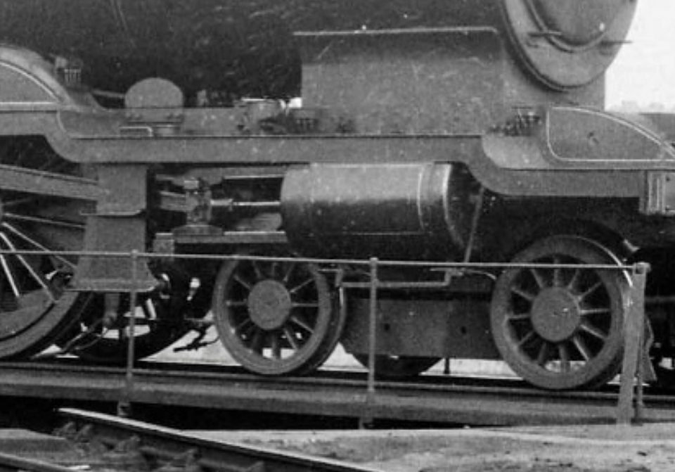
4 hours ago, 41516 said:
Brightness/contrast played with - I don't think there's a vac cylinder there either, especially when you'd expect it to be this side, looking at the brakes.
Yes, the vacuum cylinder would need to be on this side, it should always be at the opposite end to the DC brakelever on the same side.
The wagon also has 3-link couplings, highly unlikely for a (ex-)fitted wagon, which would have Instanters.
Chris
-
3 hours ago, BenL said:
But the GWRJ issue 66 article on the V12s makes it clear that this diagram also included a mix of central and offset Vs, and has photos of both. It talks about two different designs of brake gear, with the earlier one having the offset V and the later one the central V. So there doesn’t seem to be a link between the shift from offset to central Vs and the change from laminated to self-contained buffers.
As @Chris Higgs suggests above, the GWR Journal article in issue 67 on the V14 and 16s offers a different take to GWR Wagons re some of the early V14s having laminated buffers - the article classifies these early V14s as V12s, with the switch to self-contained buffers being what distinguishes V14s. So from this perspective, and contrary to a previous post I made based on GWR Wagons, some early V14s did not have laminated buffers - all V14s had self contained buffers.
Added detail: This means that what is listed in GWR Wagons as the first lot of V14s is actually a mixed lot of V12s and V14s. The GWRJ articles specify which running numbers in this lot were V12s (ie with laminated buffers) and which were V14s (ie with self-contained buffers).
Yep, agreed. The GWRJ articles make a clear assumption that spindle buffers makes the wagon a V12, self-contained a V14/16. And that is indeed what is shown on the diagram drawings.
Lot numbers (which are orders to build wagons) do not have to be built all of one diagram, as a diagram has a certain meaning to the operating departments.
I doubt that the placement of a V hanger would have significance to which diagram a wagon is placed in, it hardly affects the operational characteristics of the wagon, whereas different buffers perhaps would. The V12 diagram drawing shows a central V hanger, even though we can see the majority were offset. Whereas to modellers (well some at least!) it means more changes needed than just switching the buffers.
In a different context, Toplight coaches from different lots had variations in the panelling, toilet windows and the like, but were all placed in the same diagram.
Chris
-
1
-
-
Dare we expect these vans and wagons to appear in N/2mm, as the SECR ones are going to? I have an interest as I designed the kit versions that the 2mm Scale Association has sold for many years (resin body and etched underframe).
Chris
-
16 minutes ago, tomparryharry said:
We seem to be going at cross purposes. The photo is wagon no 100211. It's vacuum fitted, as witness the vac cylinder. We need to cross reference the 'bible'.
Sorry for any confusion.
I think the question was that the V16s were not built vacuum-fitted, perhaps it was fitted later. But the iron roof was not found on V14s, according to John Lewis.
Chris
-
On 27/12/2022 at 08:57, Dunsignalling said:
Photographs of V14s with self-contained buffers seem to indicate that the change of buffers occurred either late in the construction of the 1912 batch or from 1913.
The wagons in those photographs all feature symmetrical brake gear, suggesting that both changes were introduced together. That area is nearly always in shadow, but achieving the necessary clearance would have required either moving the cylinder inboard by an inch or two, or fitting one of smaller diameter.
There actually seems to be little difference between an early (spindle-buffered) V14 and a fitted V12, at least after the latter had received bonnet vents. However, if (as expected) the model turns out to be of a later V14, backdating it to a V12 or early V14 will involve changing the brake gear as well as the buffers.
I've not yet found a photograph of an unfitted V12 in which the brake gear is visible * in my modest library. Photo of 24927 on Paul Bartlett's website indicates they had offset vees despite not needing them. Presumably in the interests of standardisation or possible future conversion to vacuum brake.
John
* West Somerset Railway has (or had, in 1991) No. 16307 but the photo isn't informative as to brake -gear. It had though, by the time of preservation, received self-contained buffers, indicating that was possible.
Sorry if this has been mentioned before. The GWRJ article in issue 67 states that the 1912 batches of V14 were residual builds of what were to be V12s. So perhaps they just used up the parts in stock e.g. the offset Vs and the brakegear until they were gone and then switched to the symetrical Vs?
Chris
-
1
-
 1
1
-
-
20 hours ago, LNER4479 said:
As has this! A 'cut n shut' job, using two RTR PdII 68' restuarant cars as a starting point. It's a Dia.1720 in original form (ie, before being re-skinned in Stanier-esque sides) so perhaps somewhat rarer in model form than those using Comet's Dia1720a sides? Only therefore suitable for LMS days and - perhaps - never received the simplified LMS coach livery depictued before being reskinned? ... but, hey, let that be our little secret.
As the Stanier reskinning only took place in 1939-40 I'd be a bit surprised if none of the original coaches received the simplified lining earlier than that.
Chris
-
 1
1
-
-
22 hours ago, St Enodoc said:
Well, you would say that, wouldn't you?
It's what he said when he apologised to me. He had given me a bit of a black eye and that took some explaining on his part.
Chris
-
2
-
 2
2
-
-
12 hours ago, St Enodoc said:
Would my claim be rejected because I threw the rubber back?
Do you have to prove intent? The only time I was hit by one it was an accident, as the teacher had intended it for the boy sitting next to me. He obviously needed to practice more...
I seem to recall he had to apologise to my mother.
Chris
-
1
-
1
-
2
-
-
4 minutes ago, Nigelcliffe said:
Not counting the various UK-Outline RTR HO stuff I recall from when I was a teenager.....
- Nigel
Yes, it is many a long year since I have seen a Fleischmann Warship.
I suspect UK TT120 outline will go the same way as the HO stuff. Although it is not up against an established scale (OO) with masses of RTR this time.
Chris
-
22 hours ago, Grovenor said:
I would assume anyone wanting to have accurate scale wheels and track will want to have accurate bodies on their prize locos as well. Why go to that trouble otherwise? So splasher much closer to the footplate edge than they should be are not going to cut it.
Hmm, 2FS modellers make a great fuss about the track gauge being absolutely correct but accept over-width wheels and splashers. 😉
Chris
-
15 hours ago, Grovenor said:
Proto120 standards were defined by the MRSG (Model Railway Study Group) the developers of P4 back in 1966 or 67. But to use scale wheels you need to produce scale track to run on. And you will also, presumably like to have scale dimensioned stock to run on it and hence all the Hornby TT120 will need chassis rebuilds and the locos with splashers will need them relocating to suit.
See https://www.scalefour.org/history/protofoursociety/manual/2.0-proto-ratio
But at least anyone who wants to try P120 has a set of dimensions all worked out and ready.
12mm track gauge is pretty much bang-on true scale for 1:120. So I am pretty sure you would not need to move the splashers, they will already be plenty wide enough for finer wheels. The only thing you would have to do is adjust the check and wing rail gaps on TT120 points to match. Hmm, that actually makes it easier to do than if modelling in either 2FS or P4.
So is TT120 the only (UK) RTR scale where the track gauge is correct?
We don't have to move splashers on RTR locos in 2mm for the same reason, both N and 2FS end up with a total width over wheelsets which is wider then prototype, so the splashers have already been set to match this.
You could use code 40 rail, but secondary track doesn't really match the loco stock available from Hornby, which seems to just be top-link ECML.
Chris
-
On 25/12/2022 at 15:34, Chris Higgs said:
The other thing is that you might be able to pick up Farish detail packs from the Bachmann spares site.
https://Bachmann-spares.co.uk/product/category/1219/class-47-accessory-pack-372-240/f7224-219-01
-
6 hours ago, bécasse said:
Given that the fine scale TT being talked about is 1:120, or effectively 2,5FS, a tread width of 1,0 mm should be practical.
P4 (effectively "4FS") standards require a minimum tyre width of 1,85 mm, which after deducting the 0,35 mm effective flange width gives a tread width of 1,50 mm. Using the equation (2,5/4)*1,50 suggests an equivalent minimum tread width of 0,875 mm for 2,5FS.
To compare 2FS to P4 is not really that valid in my view. The equivalent of 2FS in 4mm scale would be EM standards. The tread width you suggest for TT120 would require pretty much scale checkrail gaps, which is not what 2FS has. Our checkrail gaps are 0.5mm, whereas true-to-scale would be about 0.3mm.
Pendon use an EM-Fine standard (more or less P4 tyre widths but with EM flanges).
Chris
-
1
-
-
8 hours ago, Tony Wright said:
Good morning Chris,
I'm afraid encountering nit-pickers comes with the territory of 'exhibiting'.
I personally seek out the opinions of those who really know what they're talking about. In my experience, they never come across as saying 'That's wrong!', or 'It wouldn't have been done like that!' and so on. On one early occasion in Stoke's exhibition life, the late George Pring pointed out that I'd put the wrong type of slates on the signal box's roof; most politely, and most-informatively, afterwards sending me a prototype picture. When he next saw it, those slates were the right pattern!
I'm in a privileged position in that I can ask the most-vociferous critics if I may come and photograph how they've made their own models/layouts; better/more-accurately/quicker/more-economically/easier/etc. Would it surprise you that my requests are never answered by 'Yes'?
Or, one critic who opined, when observing a layout, 'I don't think that's very good'. When I pointed out that it was all the builder's own work, yet his layout was all the product of 'chequebook modelling', he said no more. His was better, of course (I'd expect it to be), but so what? What pomposity!
Regarding exhibition running (and this was my principal 'criticism' of Heckmondwike), I think if a layout is run entirely-prototypically at a show, the result could be 'boring'. I agree, if there's some beautiful modelling on show, then the trains can be merely 'incidental'. However, after more than five minutes where nothing appeared on the scenic section (despite lots of tingling bells), I walked off rather disappointed. Obviously, my attention-span is too limited. Equally obviously, there were often long gaps between trains appearing on the real thing, even on trunk main lines. 'Spotting at Retford, the 'dead hour' was encountered in the early afternoon when, literally, no ECML train came through.
When WMRC exhibited Moretonhampstead, had we run it prototypically, we could have put up a sign for spectators; 'Please come back in three hours' time to see the same loco again, with slightly different stock'. Can you imagine the response of exhibition managers?
Speaking of signs, I was once staggered to see one on a layout at a show along the lines of 'We apologise for nothing running because of electrical problems'. I sympathised with the builders' predicament, but not the fact that the sign was not hand-written in haste, but beautifully-printed on a piece of card!
The 'ultimate' (hand-written) sign was one above a layout built by the late (and unique) Allan Downes. The layout was supposed to be operated by radio remote control, but obviously wasn't. The sign read 'Batteries Flat, Enjoy The Scenery'! I was not surprised, because I never saw any of Allan's layouts working, wonderful though the architectural modelling was. When photographing one of his layouts (Piper's Mead, possibly, or Brandy Wharf) I asked him why he'd installed a splitting distant signal by the side of a single track. Nothing wrong with that in principle, except there was no splitting of tracks beyond it and even if there were, there was no corresponding splitting home signal. His answer? ' The yellows complement the dark brown of the barn just behind them'. I loved the man!
Season's regards,
Tony.
I fear I may have been guilty myself of writing off a layout because it did not constitute what I considered exhibition worthy. There was an N gauge layout at Warley one year, I think from Warley MRS themselves, that was running a series of RTR trains that was not even from the same continent! But it had some impressive high rise buildings.
These days I would probably just conclude that if it is drawing a crowd, it can be counted a success for its target audience. After all Warley is a general model railway show, not some Scalefour gathering.
Chris
-
2
-


2FS 45xx scratch build
in 2mm Finescale
Posted
Most people just use the Dapol body (both 4500 and 4575 versions available), together with an etched chassis. It is to 1:148 scale rather than 1:152.
Very detailed original drawing in Great Western Railway Journal Issue 16. There was also long ago a drawing by Stuart Hine on how he built his scratchbuilt 45XX. He made his own motor which you don't need to do any more.
Chris