
.jpeg.93dcb7ae109704b6cdee1d9e015047dd.jpeg)
.jpeg.bbb1f906427fbb68c4f987479a3678ba.jpeg)
alanbuttler
-
Posts
752 -
Joined
-
Last visited
Content Type
Profiles
Forums
Blogs
Gallery
Events
Exhibition Layout Details
Store
Blog Comments posted by alanbuttler
-
-
.thumb.jpeg.3955886fc58580247a46965a1bd9db57.jpeg)
Thanks, though I think I'm going well beyond what's needed for an operable layout, you'd never see half of these tweaks if the loco is moving
 It's in the works with the macro lens where I'm hoping they'll add something different. Good luck with 5724
 -
I've just found the packet for the handrail knobs - they were markits short, pack of 12! That'll explain why I've none left then...
-
Here's a couple of pics Mikkel, its great -
-
Cheers mate, they are Alan Gibson short type (code 4M53). I think it was worth the effort, as a learning exercise if nothing else as I'd not done it before. Bending the handrail wire was a challenge, but heating the wire first helped no end. I was just about to order some more handrail knobs when I found they come 25 to a pack, and I can only count 11 that I've used so I must have more safely stashed somewhere....!!
-

Super work Mike, very convincing
I hope Amy made it to Farthing on her travels, hopefully Mikkel might uncover a lost painting in the corner of a brick-a-brack shop somewhere.. 
-
Your completely right, that was a compromise after I started threading the wire I realised the valve was too low! I really appreciate the feedback as a lot of the enjoyment I get from trying something new like this is understanding how the real thing works and making it look right.
-
That really looks good, Alan.
Personally, I'd be tempted to persevere with the soldering (would a different tip on the iron help?), purely for the (maybe unfounded) feeling that this imparts greater strength over the longer term?
Thanks Tim, once I'm home where I've a few more tools to employ I think drilling small holes for the wires into the capillary tube will be the answer. I used a broach on the 14BA nuts to be able to thread them onto the copper wire, I think with this plan when it comes to soldering it will stay together as it heats up. And as you say should be a lot stronger!
Thanks for the feedback, I just hope I can bring the rest of the 74xx up the same standard
-
Thanks Mike, it does like quite authentic I guess in brass and copper :-) Cheers for the tip re cleaning, I'll do that on part III, it will be a little easier at home with the rest of my tools. I'm thinking for the next one drilling guide holes into the capillary tube for the brass and copper wire, it will be more rigid and much easier to assemble. With some tigher curves I think i can get it nearer to scale. Thank God I've only got 2 to make...
-
Looks great Ian, I like the 'flow' as it were
Lots of interest and something you wouldn't normally see -
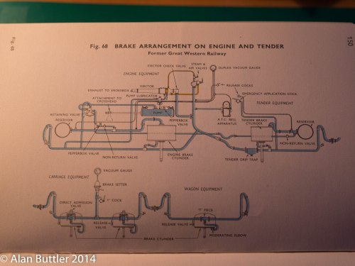
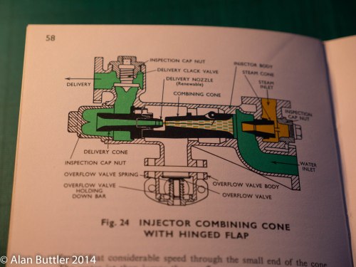
If you want I can post a couple of pics which show the detail of an injector and the relevant part of the inside of the cab on a 1366 although it has the clacks on the backhead instead of a top feed so the pipework to them follows a different route.
On yours - if you want super accuracy you need a straight rod (not a pipe with a bend in it) from the cab to the water valve just below the tank. On the 1366 this rod is above the feed to the clack so doesn't need to be cranked or bent but the 74XX could be different.
Also the steam feed pipe and the water feed into the injector are opposite each other and not at an angle - steam at the top and water coming in from underneath and it seems to be exactly the same on all the 74Xx pictures that I can find showing a decent view of an injector although the route of the steam feed from the cab front sheet varies.
That would be great if you didn't mind, it would be interesting to see what happens inside the cab. I'll take this test piece apart tonight and have a go with a jig with the parts fitted as you describe. Once I've got my 3D printer set up it will be interesting to see how it handles something as small as the injector body, if successful it will just need holes for the various wires drilling.
Cheers for the feedback gents, much appreciated!
-
Alan, I admire your tenacity and bravery to tackle such a small item to be soldered. I agree with the use of jigs to hold pieces together while soldering or gluing. I was recently using and old cork sanding block for that purpose though what I really wanted was some polystyrene packing material.
Also, I am not sure if you did this or not, but soldering longer pieces of wire which are then trimmed off may help. In my case my fingers definitely need that kind of assistance!
Thanks, I'll give the longer bits of wire a go
-
Good progress there, Alan. Before giving up on soldering, you might try making a simple jig -- just pins in a block of wood -- to hold the various pieces of wire in place as you add each part. Maybe also use a high temperature solder (188 or above) for the core parts and 145 or lower for the parts added later.
That said, I have to ask why not just use the Alan Gibson cast brass injectors. They are a good representation of this particular type and can be fairly easily modified to match the slightly different arrangements on some other GWR tanks.
Nick
Cheers Nick for the advice, the higher melt solder and jig I'll give a go. I've just looked at the Alan Gibson ones on your saddle tank and I see what you mean, they do look pretty good. I guess I'm using this as a skills developing project so even though I'll probably end up ordering the AG injectors I'll persevere. It all helps with brushing my skills up before tackling something like the 78xxx with all its appendages!
-

Looks like a Great Bear , but with more pipework . Handsome beasty .
I was thinking it had a vague Swindon look about it, maybe Churchwood knocked up the design whilst holidaying in the Nord Pas-de-Calais
-
Va va voom! Looks incredible. If Napoleon had his way we'd all have been modelling these
-
Great tip thanks Captain!
-
Great work Mike, I could have done with employing something like this on the 74xx tanks, it was a mission (a failed mission...!) getting them square
-
I think you've earned a scenic pause Mike considering how far you've come with such little info to work from!
-
Great to see this coming together Mike
-
Hi Mike, this is great thanks for posting so much detail. Shows that you don't need the latest and greatest Photoshop package to achieve such tasks.
-
This looks really good! I think that soldering white metal is far more daunting than brass, because of the risk of melting the white metal into a shapeless blob (voice of experience!)
Thanks Mike - it was using a temperature controlled iron that gave me a little help, though I did partly melt one of the front tank supports when soldering the brass cover sheet into place. After a bit of deliberation and not wanting to spend huge amounts of money I went for a Maplin 150-450 deg unit which so far has worked great.
-
Looks quite good to me. Whitemetal parts often seem a bit warped and it was that and poking a soldering iron through a cab side put me off Whitemetal.
Don
Yes its been a bit of an initiation in wielding the soldering iron, I only managed to melt one small part
-
Alan -
Good start. Bear in mind if you want to strip out the glued sections & solder them, mst epoxies don't last long with 'Nitromors' (also useful to remember if you buy a 'ready-made' kit and wnat to strip the paintwork!.
With regard to the 'top-feed', I think a glance through 'Mainly Trains' or 'Wizard Models' will probably find you one in brass, and cheaper than 'Shapeways' can do it. Unless you want the challenge, that is!
Anyway, good 'first effort' - an etched brass one next??
Regards
Ian
Thanks for the tip Ian, I'll look into that stuff. I've got a couple of chassis lined up next and then something a bit more complex - a DJH 2MT 78xxx
-
Good for you. There's a great feeling of satisfaction once you bully/coax these venerable offerings into a finished product, swearing never to do it again. Then you start another one......
Cheers Ben, it has definitely felt like some unsuccessful coaxing has been involved to get things somewhere near straight, I'll trying bullying next time
I do feel pretty satisfied this morning though after sleeping on yesterdays efforts. A bit more cleaning up and it should look good for an undercoat. -

Great stuff, that GWR.org.uk site is a superb source for research. I was just idling an hour or so looking at a branch layout design and found that Tre Pol and Pen made it up the Mawddwy branch at one point!
.thumb.jpeg.3955886fc58580247a46965a1bd9db57.jpeg)


5726 - Pipework and Pull Rods!
in Modelu's Workbench
A blog by alanbuttler in RMweb Blogs
Posted
The full copy of Handbook for Railway Steam Locomotive Enginemen is online here - https://ia600801.us.archive.org/13/items/HandbookForRailwaySteamLocomotiveEnginemen/Btc-HandbookForRailwaySteamLocomotiveEnginemen.pdf