


Lodekka
-
Posts
67 -
Joined
-
Last visited
Content Type
Profiles
Forums
Blogs
Gallery
Events
Exhibition Layout Details
Store
Posts posted by Lodekka
-
-
The Dapol 08 Doctor will see you now....
Am I the first to dismember my 08 completely?
Being quite comfortable with taking things apart and not too fussed about warranty (once I had proven it basically works).
Contemplating fitting a Zimo 644D sound chip to my 08 last night led me to start removing screws to see if access could be made as simple as possible.
So, as others have found, the body and chassis can easily be separated with two small screws (one at each end of the chassis) , remembering to carefully
disconnect the wiring/plugs inside and gently threading the chassis out of the plastic items (vac pipes, rear crossbar, pipework plugged into chassis etc.).
We now have the two parts - I want to fit a crew, the Cice art ones are very nice and a good price too..
See here http://artcice.wixsite.com/cice
Body
Therefore I needed to gain access to the cab. Removing the two side by side screws below the cab allowed the whole assembly to lift vertically away from the bodyshell.
Again, take care that the wires to the cab and marker lights are threaded out as well. The wires are thin and easily snagged..
With the cab free, it is found to be made up of two parts, the control desk and floor separates from the outer cab body by very very gently easing the cab body outward starting with the control desk end and working round (note, it may be glued) to the back of the body where there are two very small clips in each corner of the rear cab inside wall.
Once free, the two parts separate to reveal a very nicely detailed cab - you can now add more gauges/detail and crew easily.
WARNING - be careful of the hinged doors, as the fine wire pin that secures them is liable to fall out... Best keep the cab body inverted to help keep the wire in.
The main body/nose assembly is also glued to the footplate (most probably to avoid a gap showing !) although there are two recessed screws if you are needing to separate things further. I chose not to, as access is now clear to easily mount a speaker behind the nice mesh radiator grille.
The Zimo dual chamber speaker is an easy fit with plenty of room available.
It can be secured with blu-tak or a small bracket.
Also plenty of room for a small smoke generator. <a project for another report later>
Many will have found that the centre lower marker light is not active (no led fitted). I plan to add one as there is some space - albeit tight...
With a Zimo decoder a separate funcrtion can be added to drive this if required (or wire it into working with one of the others)
Chassis
Turning to the chassis...
The small circuit board can easily be removed via the two small screws on top once the wires have been unsoldered (mine were rather untidy) - and I wanted to replace them with slightly thicker wire as I intend to make my loco dual mode with a DC - DCC switch inside.
Also allowing me to add my stored charge lighting circuit for when on DC use ;-) Keeps the shunting lights on for a long period when stopped.
The plastic support frame that holds the small plug board also acts as a motor retainer and is simply clipped out of the chassis by gently prying with a small blade on each of the lower part of the four legs and the frame lifts away.
Now the motor can be lifted out from the flywheel end and the gearing examined for lubrication etc.
Actually the motor is not securely fitted, simply resting in the chassis casting cradle and secured with the plastic clip surround - this might be why some mechanisms are a bit noisy at higher speeds.
I also noticed a fair bit of sideplay in the main drive axle which may need attention later on, that plus the slop in the crank/connecting rods means a sloppy drive action.
But this is something that one of the machining fiends (like Isambard) will fix in his own inimitable style and we can all wait for a long treatise on how this is done.
Even thought he said in a previous post that he didn't plan to do any modifications - I know he will!!
Note the plastic sticky pad insulator on the base - again mine was not particularly square or ensuring a good insulator against the lower motor feed wire (Grey).
I have sleeved my motor wires separately for additional safety. The insulator is also a partial cushion against vibration but is somewhat poor at that task.
Replacing the pickup and motor connections with thicker wiring allows me to fit the DC/DCC changeover switch and rewire back to the PCB.
Plenty of room to route the wiring neatly alongside the inner frame.
Whilst on the subject of the connection PCB, I decided I did not like the DCC sound chip sitting at an angle and placing stress on the 21MTC connector.
Therefore I have performed the following modification
- Carefully unsolder and remove the two green inductors from the topside of the board.
- Refit on the underside in the same holes.
- The components are no polarity conscious so this is a simple job.
- It will be seen that they now will foul the plastic carrier - so this is a simple task to gently carve/drill away just enough of the plastic frame to allow them to sit clear with the PCB level on top. The carrier strength is slightly reduced, but it is not supporting a lot of weight or force so all will be well.
- This now means the decoder will sit level. ;-))
Re-assembling everything is (in the best traditions of a Haynes manual) a reverse of the above procedure....
So I now have a DCC sound fitted 08 that is dual switchable to DC for use on other friends layouts, and has stored charge lighting for DC use (it lasts a number of minutes and tricks many people into thinking my layout is DCC... not!)
Comment welcome.
I plan to add more later - pictures of all this to follow soon.
Lodekka.
-
I guess what I'm asking is whether I have to wire the Zimo twin speakers in series or a simple soldering to the cross bar wires joining each speaker as Digitrains kindly ommited to attach speaker wires as requested
Grateful if anyone using the Zimo LS40x20 twin speakers in their 08 can advise on where the wires are soldered at the speaker end.
Thanks
John
I have just acquired the same set-up and noted that the speakers are just linked in parallel so you should be able to attach the wires at any point (one wire to each side) along the wire links.
Think this sound solution is proving popular as they had few left at Warley when I was at the stand...
By all accounts so far this is reputedly the best sound setup for a 7m 08.
Regards
-
has anybody any suggestions for a source for a suitable figure for going in the cab please (mine will be green & no stripes when it comes, hopefully next month)
thanks
I.
Try Cice Art,
They are superbly detailed and an economical price too.
You can discuss exact details with them direct...
http://artcice.wixsite.com/cice
or call 01525 873296
NB. I have no connection other than a satisfied user of their product.
-
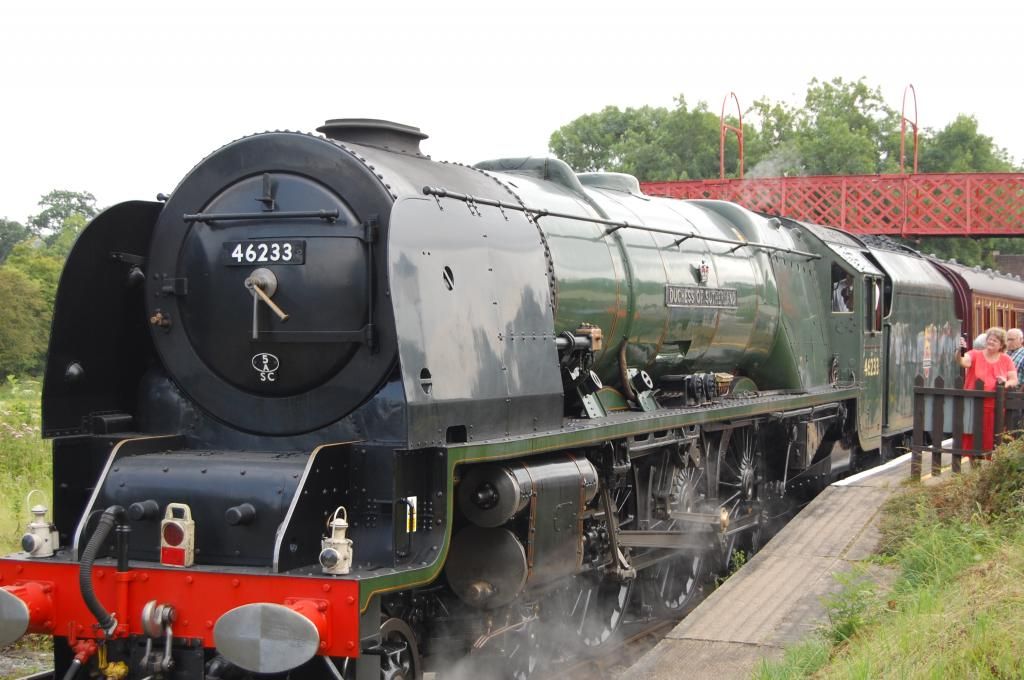
Some photo's from Butterly earlier this summer :
Duchess of Sutherland in Steam for the day
Not sure when they will get around to preserving this one, must have been one of eight or nine diesels at Butterly in various forms of degradation.
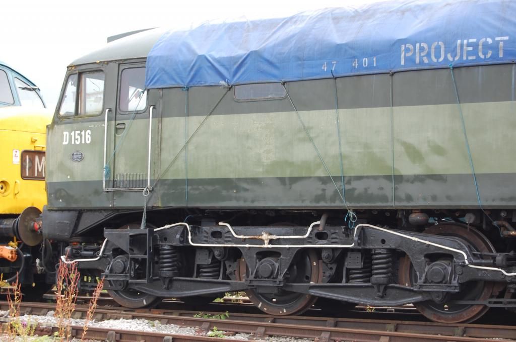
If anyone wondered where she was, well she's in the sidings at Butterly awaiting some TLC
Not an engine, but working for Royal Mail I found this TPO very interesting, after doing some checks in the archives, and talking to Butterly we can confirm that this is the TPO was involved in the Great Train Robbery, she's there in a shed complete with the bag catcher, mail bags etc, almost as if she was taken out of service the day after the robbery.
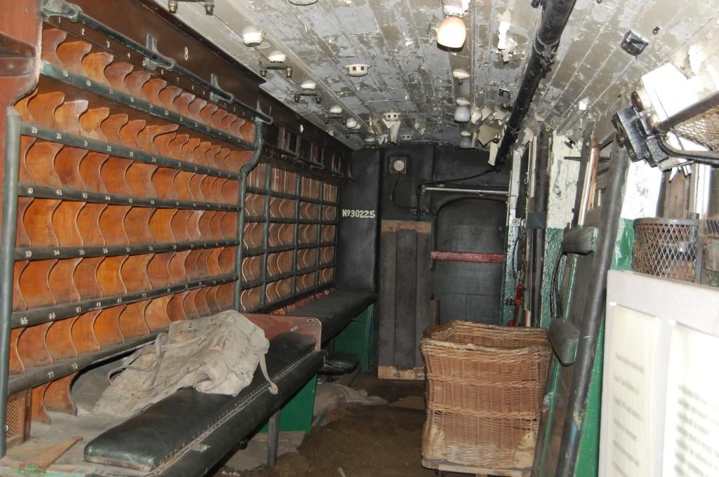
Sorry but you are wrong...
The full make up of the train was
D326 - EE Class 40
M31016M - Full Brake (BG)
M30204M - Sorting (POS) Uncoupled and involved in the actual robbery
M30291M - Sorting (POS) The rest of the train left at Sears Crossing
M30235M - Sorting (POS)
M30220M - Sorting (POS)
M30277M - Sorting (POS)
M30214M - Sorting (POS)
M30210M - Bag Tender (POT)
M30275M - Bag Tender (POT)
M30272M - Sorting (POS) Coach now preserved on the Nene Valley Railway
M30247M - Sorting (POS)
M30276M - Brake Bag Tender (BPOT)
Regrettably your coach pic does not appear...
The only survivor is at the NVR - despite the SVR claiming theirs was too!
Dapol 08
in Dapol
Posted
Postscript to the above missive...
Just a couple of supplemental notes...
When cutting the PCB mounting frame to accommodate the under mounted inductors repositioned from the topside, it is important to note that the mounting frame is handed - one side lugs are closer together, so take care to check when cutting...
Also, an omission from the first posting was that the very skinny looking vac pipes can easily be bulked up to look more realistic by adding some fine fuse wire or wire wrap wire round the original, using it as a former... Looks quite the part, needs a bit of care to make it look even but worth it.
Apart from some judicious weathering the 08 is really starting to look good...