


geoff
-
Posts
381 -
Joined
-
Last visited
Content Type
Profiles
Forums
Blogs
Gallery
Events
Exhibition Layout Details
Store
Posts posted by geoff
-
-
Piling works have progressed as far as Corby Station where the bases are up to the end of the former down side platform.
A temporary structure alongside Cottingham Rd bridge to the north of the station looks like it’s the replacement footbridge, suggesting that work on the penultimate bridge to be raised is starting soon.
Here are some photos from Tuesday 5 December 2017.
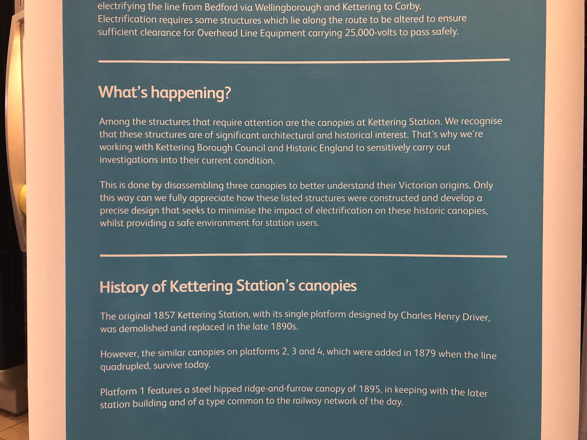
Also the new up starter at Corby station and finally some work on the Listed canopies at Kettering station.
Geoff
 IMG_0020 by Geoffrey Robinson, on Flickr
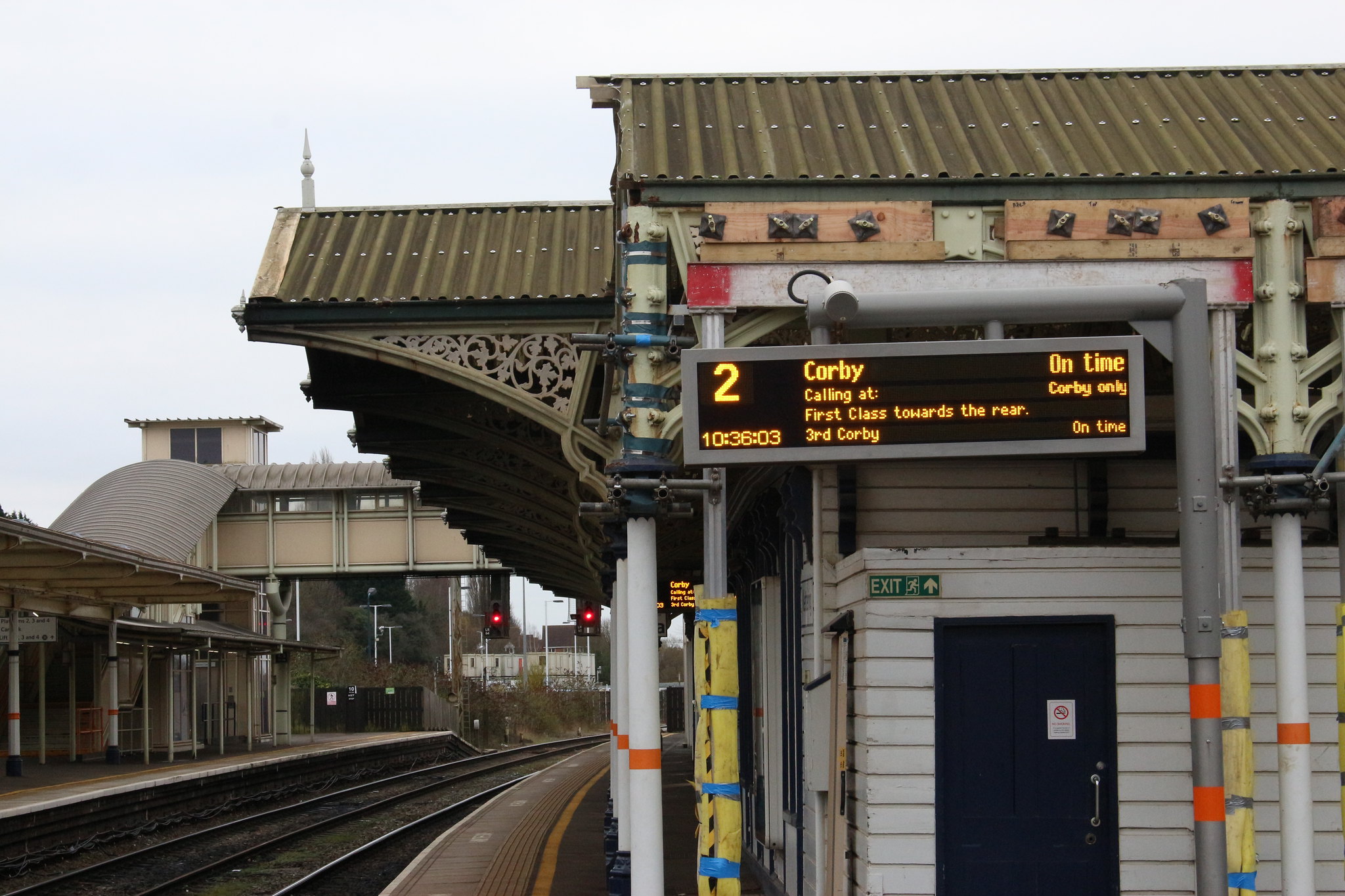 IMG_5280 by Geoffrey Robinson, on Flickr
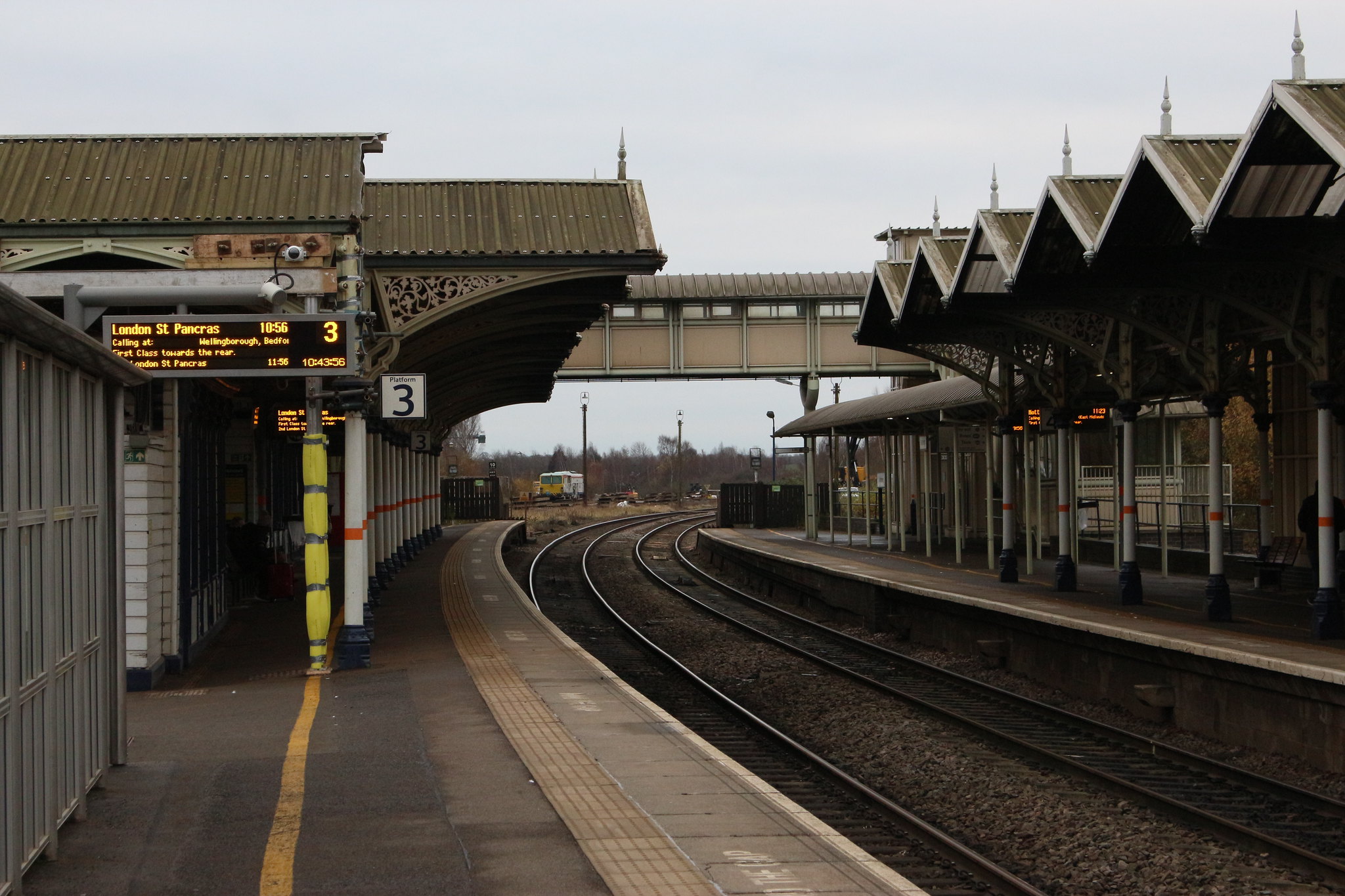 IMG_5280 by Geoffrey Robinson, on Flickr
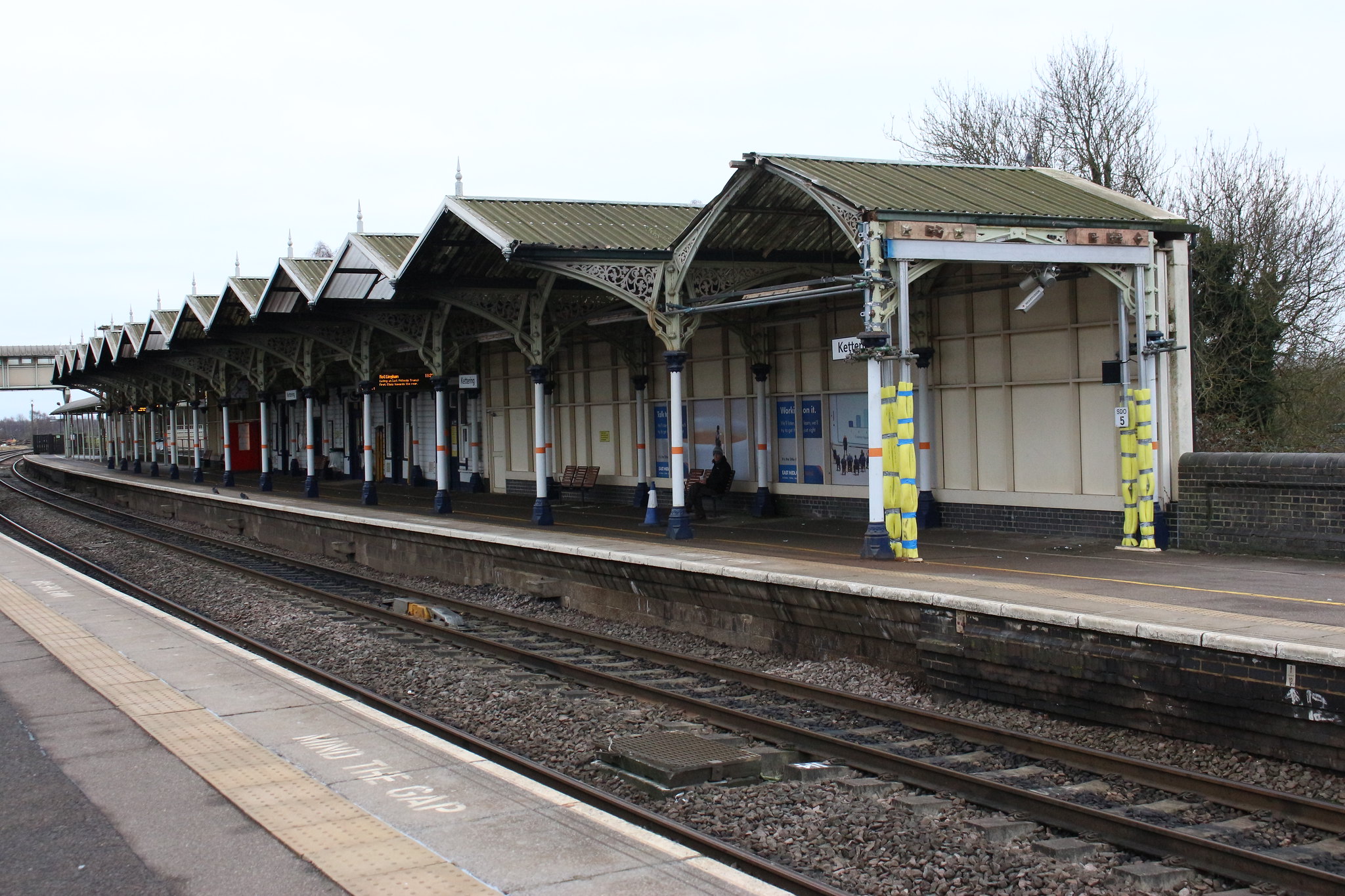 IMG_5280 by Geoffrey Robinson, on FlickrGeoff
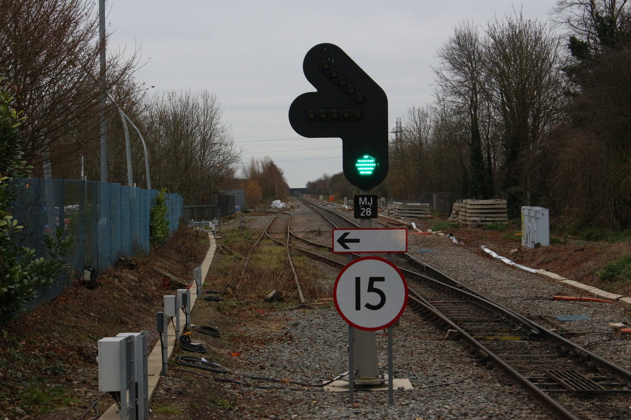 IMG_5296 by Geoffrey Robinson, on Flickr
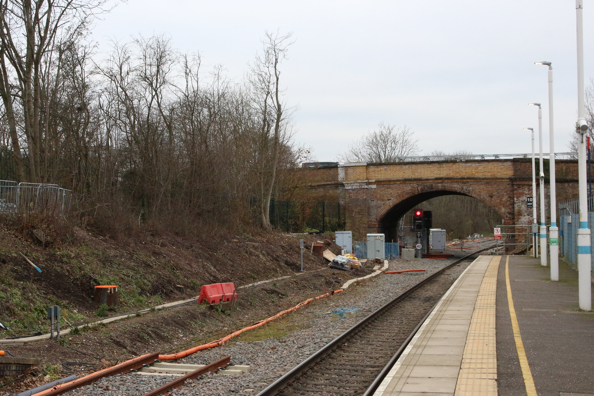 IMG_5298 by Geoffrey Robinson, on Flickr
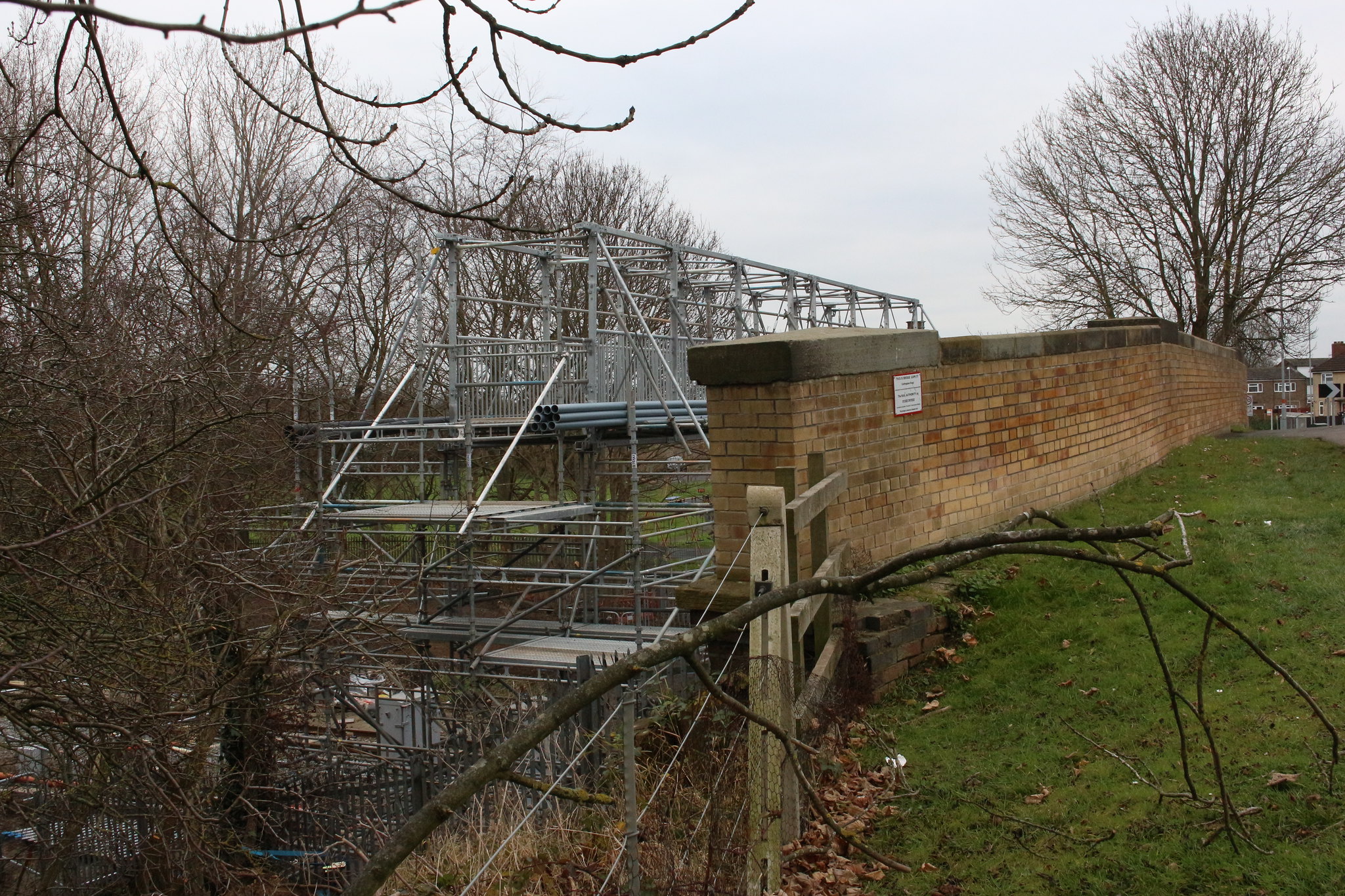 IMG_5306 by Geoffrey Robinson, on Flickr
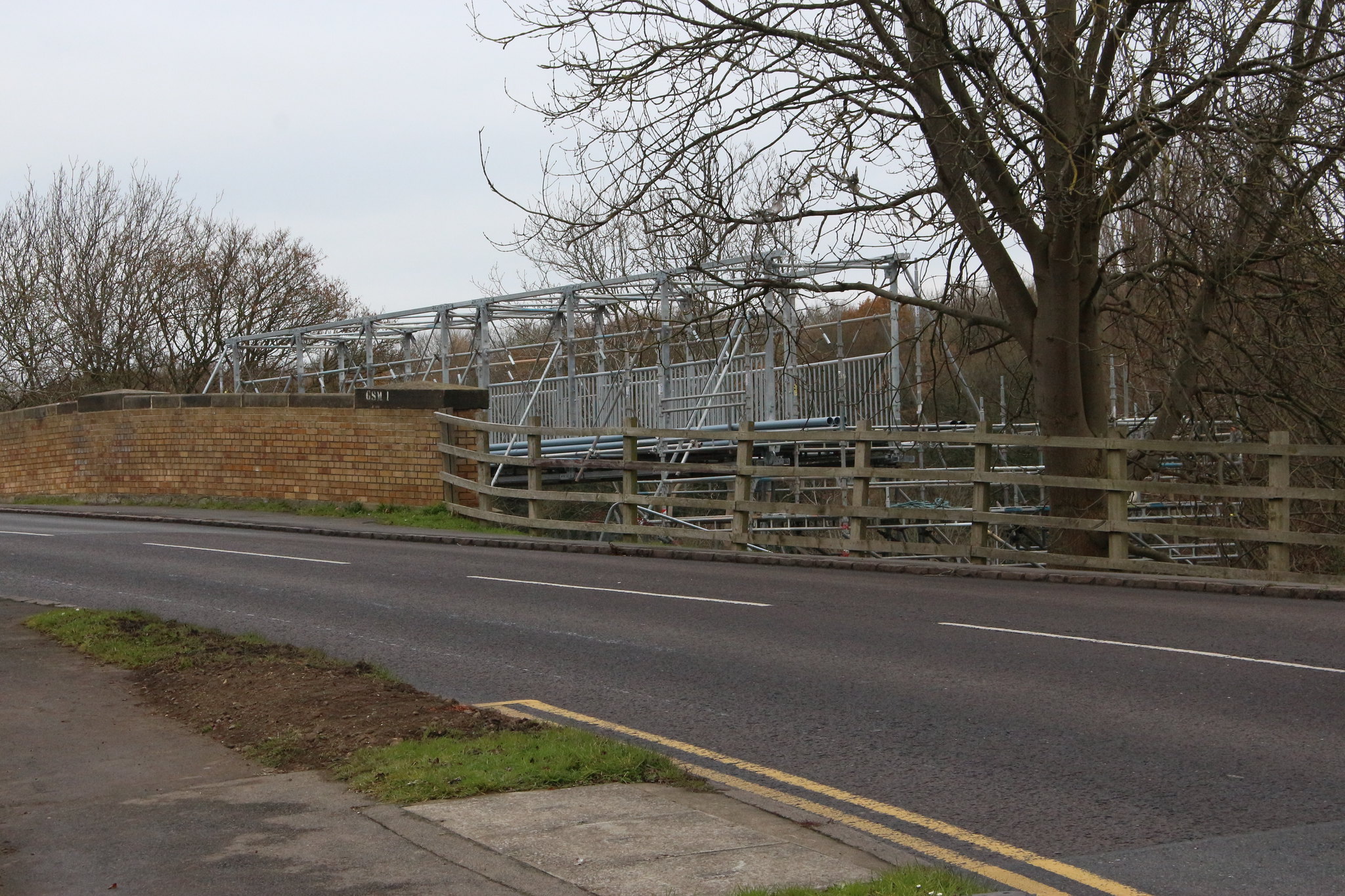 IMG_5302 by Geoffrey Robinson, on Flickr
-
 3
3
-
-
Well my future exhibition layout will be set either in the late 60s/early 70s diesel era somewhere near Bristol or in the late 50s WR steam era in Shropshire.
I could send a Gresley BG down to North Leigh in the hope that an LNER loco might be able to come to retrieve it so it can head back to its home railway . . .

Send it to Oxford and I will pick it up and take it across on the Varsity line to Cambridge or perhaps the GC at Claydon LNE Junction. It will slip back in time a few years to early 60s though.
Geoff
PS Will it need new wheel sets as I run EM gauge?

-
A couple from earlier posts which I have rotated for you Colin.
Geoff


-
4
-
-
Cheers Geoff I was just trying out the new camera but they now have a caption with a bit of info.
Cheers
Colin
Thanks Colin. Super pictures and the captions take us right there with you.
Geoff
-
Excellent Colin. If you could write some captions to tell the story, even better.
Well done.
Geoff
-
A quick trip round a couple of the work sites.

Just north of Storefield the first masts have sprouted.

Site of the former Finedon Station.

A new site compound where the Finedon Sidings used to be.
Geoff
-
2
-
-
Thanks for posting them anyway Colin. You, Jim Scott and others taking photos while on duty give us the opportunity to see the views we would not normally be able to get.
Geoff
-
Many thanks Geoff I don't know what it is I take the pics on my mobile and it was the right way up but it still uploads my pic being rotated the wrong way.
Cheers
I believe it is something to do with the way the RMweb system handles the data from phone pictures. It is a simple job to rotate them once I have grabbed them and dropped them into Photos on my mac and then I can repost them on RMweb.
My pleasure.
Geoff
-
Just one pic from tonight's spare turn it was 5C73 New St to B'ham international with an odd looking destination board.
 20171103_220651.jpg
Hold tight, just a quick spin.
Geoff

-
3
-
 1
1
-
-
Looks like I have bricked my first decoder.
I just bought a Lok programmer to update some Loksound select sound decoders in some factory equipped H0 American outline models.
First loco I tried was the Alco S4, a factory fitted Lok sound select decoder in an Atlas model.
Straightaway after about 5 minutes of it writing i would get an "Error writing decoder data" dialogue pop up and everything would stop.
I checked everything, track connection, Serial to USB driver, correct firmware version, etc. Every time I tried to write the new sound file, I got the same message after about 5 minutes!
The upshot is now, the loco has no sound although it moves OK! Furthermore, I took it to the programing track on the layout and tried a re-set but it seems not to want to re-set! CV8 should be programed to 8 to re-set but its reverts to '151' which is the decoder version number- it will not revert to 8 after a read back of the value! The loco address will also not change from '1' either!
Does anyone want a Lok programer?

When you carry out a reset by writing 8 to cv8 the decoder will always read back a value of 151 in your case or the appropriate manufacturers I'd in others. It does not read back as 8. You may also need to repeat the the reset or even cycle the power off and on for the reset to work.
Geoff
-
RTT has shown some trains terminating at Harrowden Junction late in the evening on some days recently so I took advantage of the fine weather to pop down to see what was going on.
Geoff

Track bed preparation for re-doubling at Harrowden Junction with Bush Bridge in the back ground. 24 August 2017. Compare this with the next two photos from today.


New track and new signal on the slow lines at Harrowden Junction.
And looking north towards Finedon Station Road bridge.


-
2
-
-

In the twilight of Tuesday evening, 24 October 2017, 37601 bustles through platform 4 at Kettering as the 0Z59 15:35 WEMBLEY NY NO 1 ROAD - 18:31 LEICESTER L.I.P. 4 minutes early at 1747.
Geoff
-
5
-
-
This is how I remember it!

Geoff
-
4
-
-
Many thanks Geoff I thought I had the phone the right way up to keep the pic right but the phone must be throwing a hissy fit.
Cheers
Colin
Had to Colin as Northampton (Castle) was my home town station, not that I live there now, 14 miles up the road on the Midland Main Line now. In fact I haven't been on the station since it was rebuilt again. I much preferred the original.
Geoff
-
Only one photo from me tonight 350368 at Northampton about to work 1Y85 the 2156 Northampton to Crewe service via Coventry and New St.
So much for being spare today as I copped a New St turn and it was non stop except my bare minimum PnB.

Geoff
-
2
-
-

Having been disillusioned with the way British 00 was heading with costs thought I would give US railroading a go, this has proved a winner as I have found obtaining US outline in the UK quite challenging it is back to scratchbuilding and proper modelling.
This is the Weyerhauser factory in one corner.
-
8
-
-
I have just installed the new 'streamlined' sketch and all is working just hunky dorey. Thank you Ray, Ian and all who have contributed to this thread. You have all enabled me to move from a frustratingly unreliable turntable to a really useful unit.
Thank you all very much indeed.
Geoff
-
So here's a tidied up version of the 180 degree turntable removing a lot of unnessarsary stuff as we are using just one DCC accessory address..
The following definitions are the only values you need to change to suit your system.
#define road 2706        //Adjust 'road' for correct position
#define road180 1098     //Tweak 'road180' for 180deg rotation
#define dccaddress 400   // DCC address to respond to
and the complete sketch
////////////////////////////////////////////////////////////////////////////////
//
// 180 Degree DCC Turntable (Accessory Address 400)

#include <DCC_Decoder.h>
#include <AccelStepper.h>
#include <Wire.h>
#include <Adafruit_MotorShield.h>
#include "utility/Adafruit_PWMServoDriver.h"

//////////////////////////////////////////////////////////////////////////////////////////////////////////////////////////////////////
//////////////////////////////////////////////////////////////////////////////////////////////////////////////////////////////////////
//
// Defines and structures
//
#define kDCC_INTERRUPT            0
                         // define road positions
                         // 'road' must be greater than 'road180'
                         // road-road180 should be approx 1600
#define road 2706        //Adjust 'road' for correct position
#define road180 1098     //Tweak 'road180' for 180deg rotation
#define dccaddress 400   // DCC address to respond to

////////////////////////////////////////////////////////////////////////////////
////////////////////////////////////////////////////////////////////////////////
//
// Adafruit Setup

Adafruit_MotorShield AFMStop(0x60); // Default address, no jumpers

// Connect stepper with 200 steps per revolution (1.8 degree)
// to the M3, M4 terminals (blue,yellow,green,red)

Adafruit_StepperMotor *myStepper2 = AFMStop.getStepper(200, 2);

// you can change these to SINGLE, DOUBLE, INTERLEAVE or MICROSTEP!

// wrapper for the motor! (3200 Microsteps/revolution)
void forwardstep2() {
  myStepper2->onestep(FORWARD, MICROSTEP);
}
void backwardstep2() {
  myStepper2->onestep(BACKWARD, MICROSTEP);
}
 void release2() {
  myStepper2->release();
}

// Now we'll wrap the stepper in an AccelStepper object

AccelStepper stepper2(forwardstep2, backwardstep2);

//////////////////////////////////////////////////////////////////////////////////////////////////////////////////////////////////////
//////////////////////////////////////////////////////////////////////////////////////////////////////////////////////////////////////
//
// Basic accessory packet handler
//
void BasicAccDecoderPacket_Handler(int address, boolean activate, byte data)
{
        // Convert NMRA packet address format to human address
    address -= 1;
    address *= 4;
    address += 1;
    address += (data & 0x06) >> 1;

    boolean enable = (data & 0x01) ? 1 : 0;

        if( address == dccaddress )  //DCC accessory address
        {
            Serial.print("Basic addr: ");
            Serial.print(address,DEC);
            Serial.print("   activate: ");
            Serial.println(enable,DEC);

            if( enable )
              {
                stepper2.moveTo(road180);
              while (stepper2.currentPosition() > road180) {
                stepper2.run();
                    }
                delay(1000);
                release2();
                Serial.println("Release ");
              }
           else
              {
                stepper2.moveTo(road);
              while (stepper2.currentPosition() < road) {
                stepper2.run();
                    }
                delay(1000);
                release2();
                Serial.println("Release ");
              }
       }
}


//////////////////////////////////////////////////////////////////////////////////////////////////////////////////////////////////////
//////////////////////////////////////////////////////////////////////////////////////////////////////////////////////////////////////
//
// Setup
//
void setup()
{

   Serial.begin(9600);

   AFMStop.begin(); // Start the shiel

//configure pin3 as an input and enable the internal pull-up resistor
  pinMode(3, INPUT_PULLUP);
//read the sensor (open collector type) value into a variable
  int sensorVal = digitalRead(3);

//set stepper motor speed and acceleration
  stepper2.setMaxSpeed(30.0);
  stepper2.setAcceleration(20.0);

// if near reference point move away
  sensorVal = digitalRead(3);
  while (sensorVal == LOW) {
    sensorVal = digitalRead(3);
    forwardstep2();
      delay(50);
  }

// step forward to sensor index point
  while (sensorVal == HIGH) {
    sensorVal = digitalRead(3);
    forwardstep2();
      delay(50);
  }

  delay(1000);
  stepper2.moveTo(road-800); // somewhere between road and road180
  while (stepper2.currentPosition() < road-800) {
                stepper2.run();
                    }
                delay(1000);
                release2();

   DCC.SetBasicAccessoryDecoderPacketHandler(BasicAccDecoderPacket_Handler, true);
   DCC.SetupDecoder( 0x00, 0x00, kDCC_INTERRUPT );
}

//////////////////////////////////////////////////////////////////////////////////////////////////////////////////////////////////////
//////////////////////////////////////////////////////////////////////////////////////////////////////////////////////////////////////
//
// Main loop
//
void loop()
{
    static int addr = 0;

        ////////////////////////////////////////////////////////////////
        // Loop DCC library
    DCC.loop();

        ////////////////////////////////////////////////////////////////
        // Loop Stepper

    stepper2.run();

}

//////////////////////////////////////////////////////////////////////////////////////////////////////////////////////////////////////
//////////////////////////////////////////////////////////////////////////////////////////////////////////////////////////////////////
again have fun and thanks to Paul and Ian for their input.
Ray.
Thanks Ray. I presume even with this version I would still have to alter the line beginning "utility/Adafruit etc to include _ MS in front of the _PWMServo etc to suit the code I have for my motor shield.
Geoff
-
Hi Geoff...
sounds to me like you need either
1) a dcc interface board
2) dcc interface with arduino headers and an i2c output
www.dccinterface.com
both available from me :-)
( taking advantage of the situation )
Thanks Ian, it was just a wire pulled out of a screw connector block, not even completely out, but just not making contact which is why I didn't notice it while I was grovelling about under the railway swapping the connections over. It is all sorted now thanks.
Geoff
-
Hello Ray, well after much tribulation I have got the new programming working. First trip up was the line "utility/Adafruit_PWMServoDriver.h" which has to be changed to include _MS in front of _PWM----etc. I omitted to change that. Then, because I have no understanding of programming I get a little confused by the combination of symbols and 'conversational' language but I eventually sorted my brain out only to find the table stopping halfway between the two track positions and not responding to any commands.I finally tracked that down to one of the DCC wires to the interface board having been dislodged, presumably when I swapped over the power connections to connect the usb from my MacBook. But it is all sorted now and working just as you predicted. Thank you so much for giving up more of your time, I am very grateful.
Best regards.
Geoff
-
1
-
-
Hi Geoff (and anybody else looking in).
As promised here is the new code for a 180 degree Turntable which powers down the stepper after reaching the desired position. Getting rid of that annoying 'whine' and keeping the motor cool.
The are
two three sections that need to be modified to suit your turntable.// 'road' must be greater than 'road180' // road-road180 should be approx 1600 int road = 2706; //Adjust 'road' for correct position int road180 = 1098; //Tweak 'road180' for 180deg rotationAs it say's adjust the value following 'road' and 'road180' to suit your turntable.
If you used the previous version you can just plug-in your existing values that you used in the 'stepper2.moveTo' statements or start again with what's here.
The other is:
stepper2.moveTo(1900); // somewhere between road and road180 while (stepper2.currentPosition() < 1900) {Like it say's again, make value of 'moveTo' and 'currentPosition' roughly half way between the values in 'road' and 'road180'
oh, and I nearly forgot, set the address to whatever accessory address you want to use.
gAddresses[0].address = 400;
So here's the complete sketch:
////////////////////////////////////////////////////////////////////////////////
//
// DCC Turntable Control Test Routines (Accessory Address 200)

#include <DCC_Decoder.h>
#include <AccelStepper.h>
#include <Wire.h>
#include <Adafruit_MotorShield.h>
#include "utility/Adafruit_PWMServoDriver.h"

//////////////////////////////////////////////////////////////////////////////////////////////////////////////////////////////////////
//////////////////////////////////////////////////////////////////////////////////////////////////////////////////////////////////////
//
// Defines and structures
//
#define kDCC_INTERRUPT            0

typedef struct
{
    int               address;                // Address to respond to

}

DCCAccessoryAddress;

DCCAccessoryAddress gAddresses[1];

////////////////////////////////////////////////////////////////////////////////
////////////////////////////////////////////////////////////////////////////////
//
// Adafruit Setup

Adafruit_MotorShield AFMStop(0x60); // Default address, no jumpers

// Connect stepper with 200 steps per revolution (1.8 degree)
// to the M3, M4 terminals (blue,yellow,green,red)

Adafruit_StepperMotor *myStepper2 = AFMStop.getStepper(200, 2);

// you can change these to SINGLE, DOUBLE, INTERLEAVE or MICROSTEP!

// wrapper for the motor! (3200 Microsteps/revolution)
void forwardstep2() {
  myStepper2->onestep(FORWARD, MICROSTEP);
}
void backwardstep2() {
  myStepper2->onestep(BACKWARD, MICROSTEP);
}
 void release2() {
  myStepper2->release();
}

// Now we'll wrap the stepper in an AccelStepper object

AccelStepper stepper2(forwardstep2, backwardstep2);

//////////////////////////////////////////////////////////////////////////////////////////////////////////////////////////////////////
//////////////////////////////////////////////////////////////////////////////////////////////////////////////////////////////////////
//
// Decoder Init
//
void ConfigureDecoder()
 {
    gAddresses[0].address = 400;
 }

//////////////////////////////////////////////////////////////////////////////////////////////////////////////////////////////////////
//////////////////////////////////////////////////////////////////////////////////////////////////////////////////////////////////////
//
// Basic accessory packet handler
//
void BasicAccDecoderPacket_Handler(int address, boolean activate, byte data)
{
        // Convert NMRA packet address format to human address
    address -= 1;
    address *= 4;
    address += 1;
    address += (data & 0x06) >> 1;

    boolean enable = (data & 0x01) ? 1 : 0;

                          // 'road' must be greater than 'road180'
                          // road-road180 should be approx 1600
    int road = 2706;      //Adjust 'road' for correct position
    int road180 = 1098;   //Tweak 'road180' for 180deg rotation

        if( address == 400 )  //DCC accessory address
        {
            Serial.print("Basic addr: ");
            Serial.print(address,DEC);
            Serial.print("   activate: ");
            Serial.println(enable,DEC);

            if( enable )
              {
                stepper2.moveTo(road180);
              while (stepper2.currentPosition() > road180) {
                stepper2.run();
                    }
                delay(1000);
                release2();
                Serial.println("Release ");
              }
           else
              {
                stepper2.moveTo(road);
              while (stepper2.currentPosition() < road) {
                stepper2.run();
                    }
                delay(1000);
                release2();
                Serial.println("Release ");
              }
       }
}


//////////////////////////////////////////////////////////////////////////////////////////////////////////////////////////////////////
//////////////////////////////////////////////////////////////////////////////////////////////////////////////////////////////////////
//
// Setup
//
void setup()
{

   Serial.begin(9600);

   AFMStop.begin(); // Start the shiel

  //configure pin3 as an input and enable the internal pull-up resistor
  pinMode(3, INPUT_PULLUP);
  //read the sensor (open collector type) value into a variable
  int sensorVal = digitalRead(3);

  //set stepper motor speed and acceleration
  stepper2.setMaxSpeed(30.0);
  stepper2.setAcceleration(20.0);
//  stepper2.moveTo(800);

// if near reference point move away
  sensorVal = digitalRead(3);
  while (sensorVal == LOW) {
    sensorVal = digitalRead(3);
    forwardstep2();
      delay(50);
  }

// step forward to sensor index point
  while (sensorVal == HIGH) {
    sensorVal = digitalRead(3);
    forwardstep2();
      delay(50);
  }

  delay(1000);
  stepper2.moveTo(1900); // somewhere between road and road180
  while (stepper2.currentPosition() < 1900) {
                stepper2.run();
                    }
                delay(1000);
                release2();

   DCC.SetBasicAccessoryDecoderPacketHandler(BasicAccDecoderPacket_Handler, true);
   ConfigureDecoder();
   DCC.SetupDecoder( 0x00, 0x00, kDCC_INTERRUPT );
   release2();
}

//////////////////////////////////////////////////////////////////////////////////////////////////////////////////////////////////////
//////////////////////////////////////////////////////////////////////////////////////////////////////////////////////////////////////
//
// Main loop
//
void loop()
{
    static int addr = 0;

        ////////////////////////////////////////////////////////////////
        // Loop DCC library
    DCC.loop();

        ////////////////////////////////////////////////////////////////
        // Loop Stepper

    stepper2.run();

}

//////////////////////////////////////////////////////////////////////////////////////////////////////////////////////////////////////
//////////////////////////////////////////////////////////////////////////////////////////////////////////////////////////////////////
Have fun.
Ray.
Thank you Ray. I will have a go at this sometime tomorrow.
Geoff
-
Emergency back up?
Geoff
60103 Flying Scotsman rounds the corner from Glendon South with the 1Z60 0843 West Coast Railway Company service from London Victoria to York, about 7 minutes late at 1142 on Friday 15 September 2017.
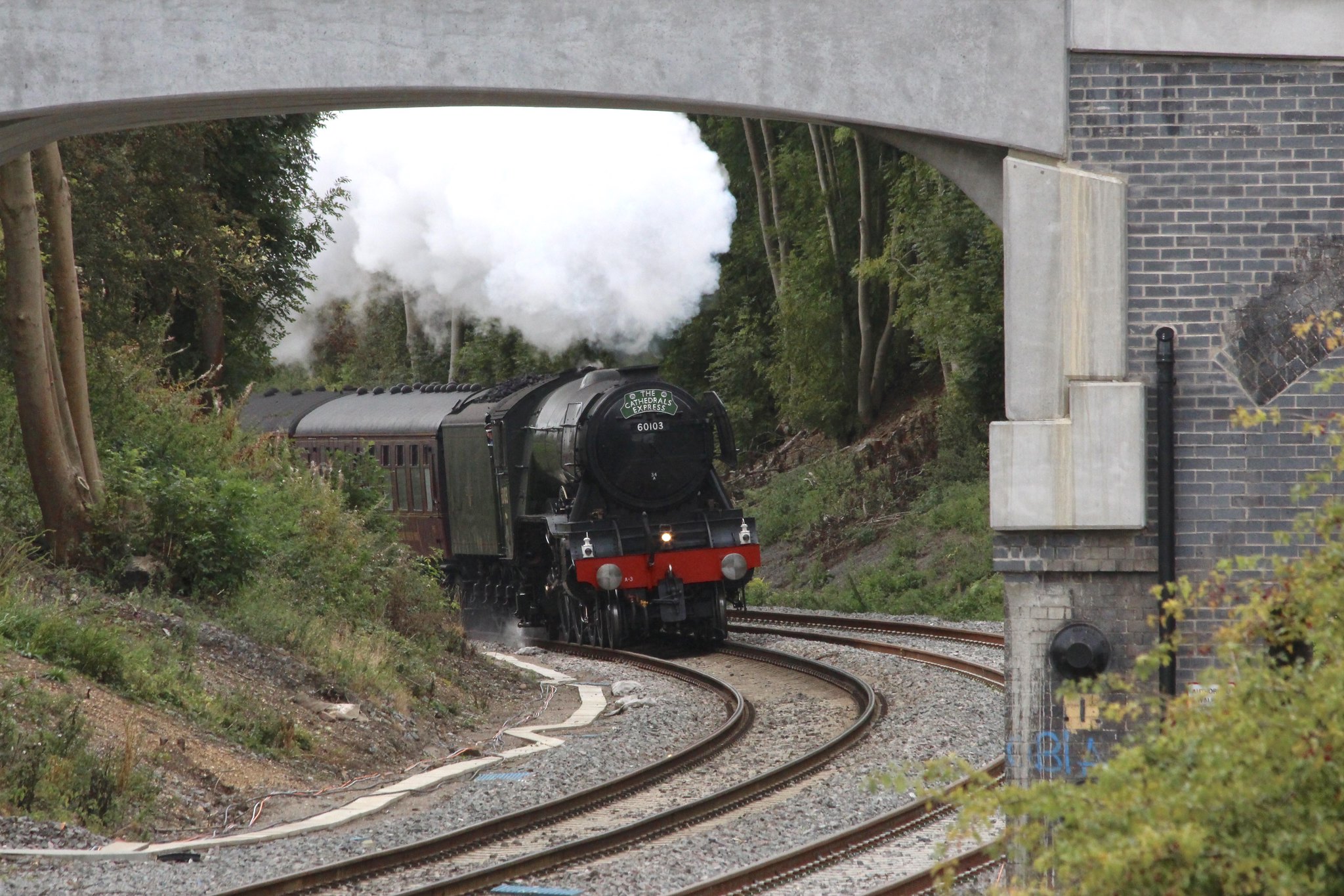 IMG_4882 by Geoffrey Robinson, on Flickr
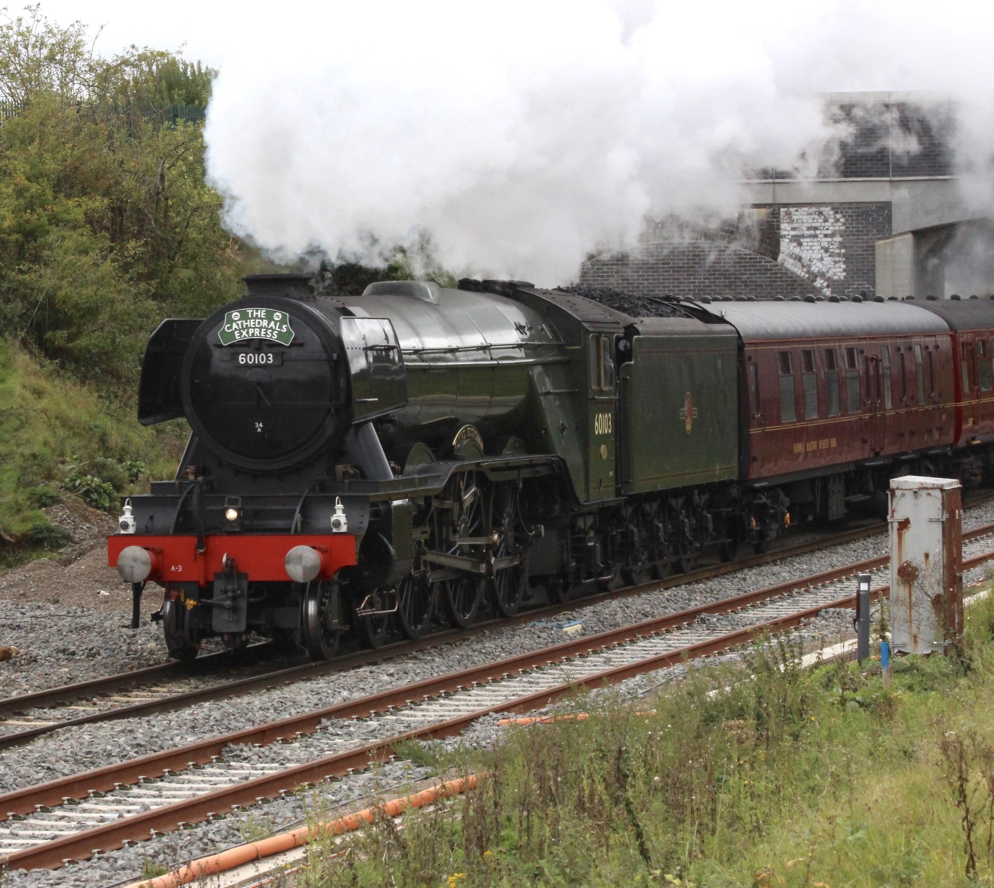 IMG_4886 by Geoffrey Robinson, on Flickr
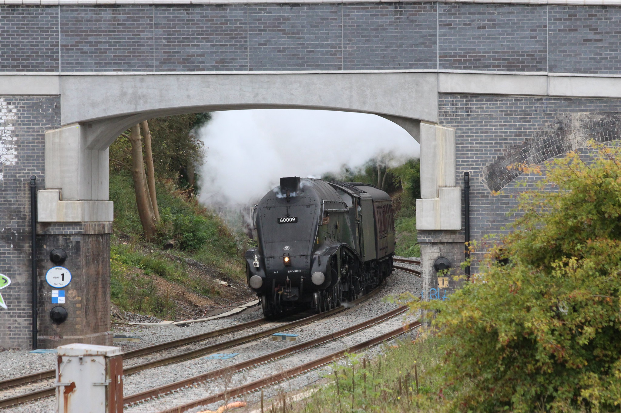
60009, Union of South Africa, leads the 1Z60 0631 London Victoria to York, West Coast Railway company Service round the corner from Glendon South 2 minutes late at 1000 on Saturday 23 September 2017. WCR class 57, 57314 appeared to contributing significantly at the rear.
 IMG_4909 by Geoffrey Robinson, on Flickr
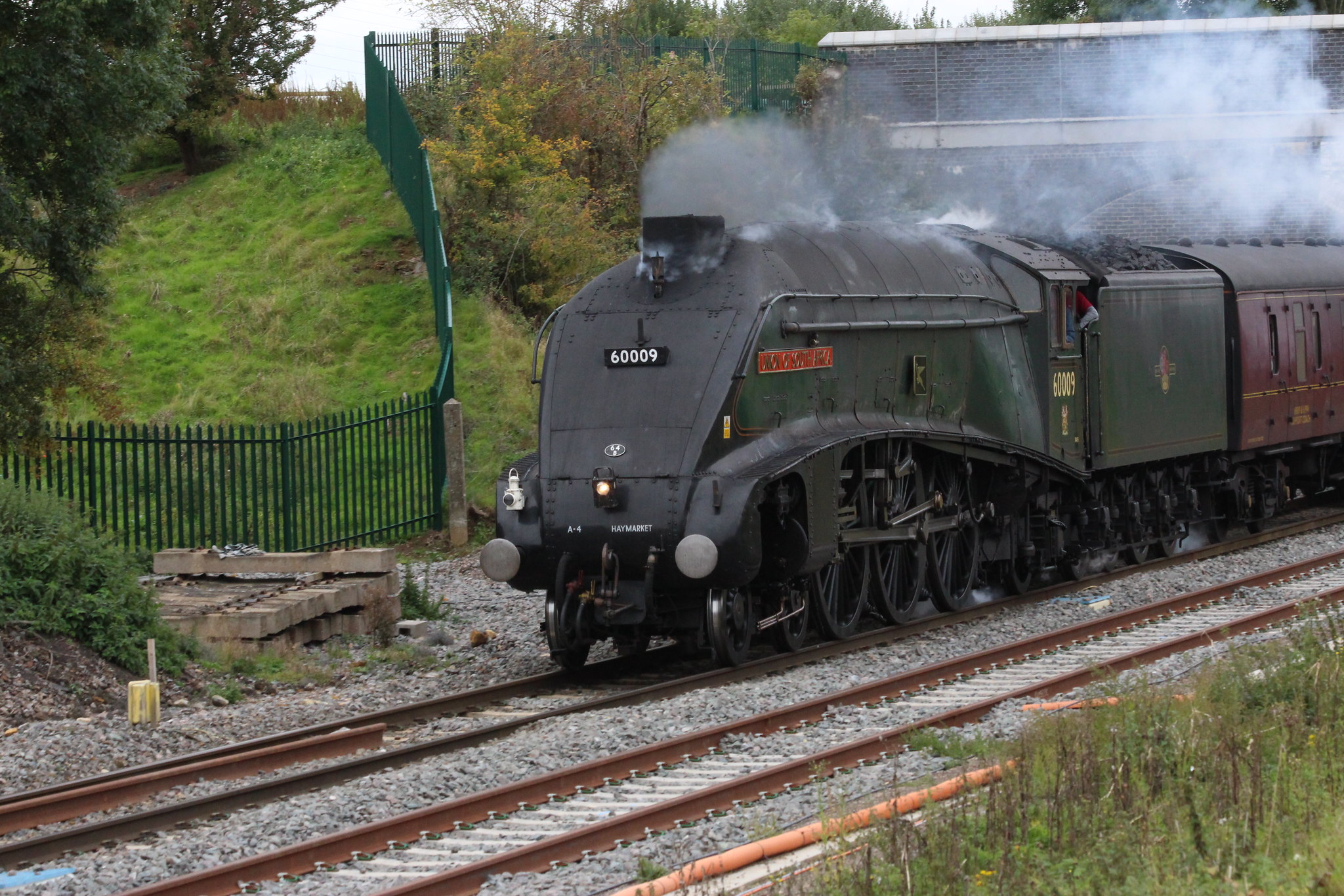 IMG_4910 by Geoffrey Robinson, on Flickr
-
6
-
-
Some incidental work ongoing at the Glendon Road bridge.


This looks to be a base for a 'pad mount' distribution sub-station possibly to replace the pole mounted transformer on the opposite side of the road which has not long replaced a much older and smaller capacity single pole mounted transformer which from memory was only a 25kva unit.


Ground works adjacent to Kettering North Junction.

Work on cabinets immediately adjacent to the Glendon road bridge on the down side of the main line.
Geoff
-
7
-
-
Ian, did you get my email with the sketch?
Geoff


Class 47 photos
in UK Prototype Discussions (not questions!)
Posted
A blast from the past. Harrowden Junction looks a great deal different today. Some years ago and at astronomical cost the relief line was extended to Kettering South Junction and now, at an even greater cost, the line is being doubled to restore it to a four track section as it had been for a hundred years. Cost savings???
Geoff
47777 sounding off beat as it passes Harrowden Junction with a Serco train at 1338 on Tuesday 2 November 1999.