


geoff
-
Posts
381 -
Joined
-
Last visited
Content Type
Profiles
Forums
Blogs
Gallery
Events
Exhibition Layout Details
Store
Posts posted by geoff
-
-
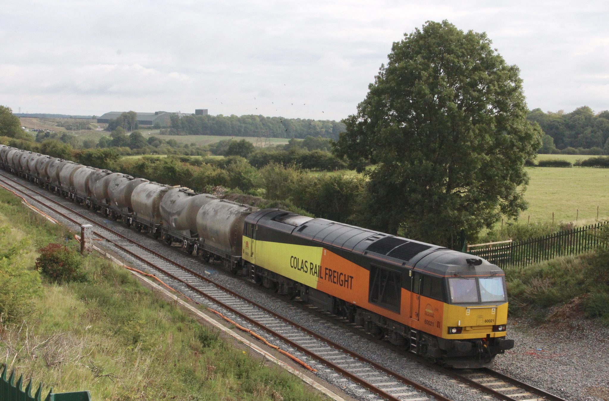
My goodness, 60021 was passing through Northamptonshire en-route from Oxwellmains to West Thurrock on the 14th, see post 2348 in the fall and rise of the 60s. I wonder how many miles these locos cover in a month?
Geoff
-
I wonder how many drivers are required to work this train? A long distance run for a Colas class 60.
 IMG_4849 by Geoffrey Robinson, on Flickr
60021 leads the 6L44 20:28 OXWELLMAINS LAFARGE COLAS - 13:06 WEST THURROCK SIDINGS FHH down towards the Glendon Iron Coy. bridge on time at 09:45 on Thursday 14 September 2017.
-
 4
4
-
-
I presume that means that I can continue to use the ESU software with their programmer with no risk to my Mac? Should that be so the only thing I am retaining the Windows laptop for will be gone and it can go in a skip. Are there any downsides to running Windows 7 on a Mac?
Three very useful responses. Thanks guys! The link, Nick G, is very useful and I will study it in detail before I do anything further.
Chaz
Chaz, for many years I used a Lokprogrammer on a MacBook pro with Parallels to give the Windows environment. In fact it worked more seamlessly than on a windows machine. I eventually bought a refurbished windows laptop for my railway because I have an old windows based programme I use for train scheduling and the cost of updating Parallels to allow me to update my MacBook was prohibitive, far more than the windows laptop.
Further comment about your iPad mini; should you wish to use the jmri free software for programming you will not be able to use your iPad as they do not run Java which is necessary for the jmri software to operate.
Geoff
-
I picked up the following today from a local railway interest site I use.
Geoff
Kettering station
I have just called in to the station on my walk with the dog and there is a planning application from network rail to the council for partial dismantling of the canopies
on the station for the electrification of the line. Copies can be seen at the council office in bowling green road ,it does not say which platforms - watch this space .
-
My internet was very slow yesterday so I could not visit the Adafruit website. As far as I can the TB6612 driver on that board is a dual Mosfet H-bridge really intended for driving DC motors. The specialized stepper driver chips have a lot of features specifically aimed at getting the best from stepper motors.
...R
Robin, thank you for taking the time to look into this.
Since I started on this project completely ignorant of Arduino, Adafruit motor shields, stepper motors and their application I felt I had to go with the original parts lists with which Ray started the thread. I now have a turntable which I can use and which seems to operate reliably for what I require so I am content to go with what I have. But my journey to this end and the other projects which have come up in the thread have no doubt enriched and enlightened anyone who has used the thread to further their own plans and for that I am grateful to all who have contributed.
Thanks again.
Geoff
-
If it does not have an adjustment for the motor current then it is not a specialized stepper motor driver - such as a Pololu DRV8825.
As well as allowing for adjusting the current the specialized drivers relieve the Arduino of a lot of work as they only need step and direction signals.
...R
Robin, mine is an Adafruit Industries Motorshield v2.3, DC motor, stepper and servo control for Arduino.
Geoff
-
They have one?
Will have to check mine and set.
Thanks.
CFJ
This thread has certainly thrown up some interesting snippets of information about the products which have been used. I received no documentation with my stepper motor and was very surprised and concerned when I discovered how hot it became with prolonged use. When looking for the information about connecting the motor shield to the Arduino I didn't see any mention of an adjustable current limiter. It must be that darned small print that I just cannot see even with my new glasses. We live and learn.
Thanks to all who have contributed I have a useable turntable now. I am very grateful for all the time and effort people have given over to this project and in particular with helping me get mine working.
Geoff
-
Geoff,
When you release the motor it is no longer "locked" in place.
If it is moved accidentally and your code relies on the last known position then won't work too well.
For my controller, it releases after several minutes of inactivity but seeks a home position on reactivation.
CFJ
Hello CFJ,
Yes I understand that the motor is not locked in place if it is released. In practice I find the table does not move when running locos on or off and so far I have found that it works reliably using that method and I don't have to fret about the temperature of the motor.
Ray has said he might investigate further when he gets time and he has given up so much time helping me with this already. If there is another sketch which will help to keep the motor cool while providing the quality of operation we are currently getting I am sure we would all appreciate finding out about it.
Thank you for contributing to the thread.
Geoff
-
Ray,
I managed to nip up to the railway this evening and make the alterations to the sketch and they work just fine. I tried them first with the computer hooked up and then with the link jumper in place and the power to the Arduino and everything worked as you predicted.
Thank you very much indeed.
Geoff
-
1
-
-
Ok Geoff, here's something to be going on with, it's not perfect yet but it will power down the motor.
Add the following after:
void backwardstep2() {
myStepper2->onestep(BACKWARD, MICROSTEP);
}
void release2() {
mystepper2->release();
}
Then after your two 'stepper2.moveTo(xxxx);' commands add:
release2();
Finally after 'DCC.SetupDecoder( 0x00, 0x00, kDCC_INTERRUPT ); add:
release2();
This will power down the motor after finding the first reference position after switching on.
The select a turntable road by sending a DCC accessory address. The turntable will rotate to that position but the motor will stay powered while the loco is rolled on/off the turntable. Select the same turntable road again and the motor will power down.
Selecting a new turntable road and it will power up and rotate to the new position.
It's not a perfect solution but I'll work on it when I get a bit more time.
Ray.
Gosh, that was fast Ray. I will give that a go tomorrow sometime.
Thank you once again.
Geoff
-
Hi Geoff.
Something I hadn't realised is there is a 'release' command in the Adafruit library which is supposed to power down the motor. I'm not sure if this relates to a stepper motor or a DC motor (or both) which the Adafruit board can also drive. I'll investigate when I get a few minutes and report back. This would be a more elegant solution.
Ray
It certainly would Ray, thank you.
Geoff
-
Good evening Ray,
I have arrived at position settings which give consistent alignment, with or without a loco on the table. They are 1078 and 2706, someway off a difference of 1600 but they work.
I then went on to testing the alignment with the motor powered down and that worked fine. Following that I shut down the Arduino software on the computer and the turntable continued to operate consistently. Finally I disconnected the usb connection, inserted the jumper link and powered the two boards from the Arduino power socket and that also worked nicely. The only negative, from my point of view, was that powering down the Arduino to swap the connections meant that the turntable moved to the sensor position on powering up again. That is not a major issue I guess.
Since I worry about the temperature of the motor I would like to be able to disconnect the power to the motor when I am not turning a loco so would it be feasible to remove the jumper link and tap off the power to the Arduino board and take a supply to the motor shield via a switch so that I can leave the Arduino powered up and just energise the shield when I want to turn a loco?
Once again I need to thank you and Ian for all the help and guidance you have given me with this project.
Geoff
-
No problem Geoff, I've been meaning to get back into this for some time.
So to summarise the above.
Adjust the higher (moveTo) value for the correct position, then tweak the lower (moveTo) value for 180deg rotation.
Ray
Thanks Ray. I will give that a go tomorrow sometime and report back.
Geoff
-
Hi Geoff, I'm back. Sorry it took so long. The last time I complied the turntable code was a few years ago when I was running version 1.05 of the IDE.
I now have the latest version and some some reason it wouldn't complie the DCC libraries. Took a bit of head scratching for the last day or so, then I remembered somewhere back in the thread that there was a new download location for them.
So I downloaded a new set of DCC libraries and hey presto I have a working system again.
I have just reloaded my version of DCC Test from page 1 just to male sure it does what it supposed to and I think I have reproduced your problem.
With the two 'goto' values of 400 and 2000 there's about a rails width error when rotating back and forth 180deg.
I think the reason is that micro stepping isn't very accurate as we are trying to hold the stepper between two steps but it is repeatable.
I found by adjusting the values to 398 and 2000 the turntable would rotate back and forth 180deg without any error.
You will probably have to set the values for your system as you have a different exit position but found setting the highest value position first (after the sensor detect) and then working back to the lower value position gave the best result.
i.e. when rotating back to the lower value position if it overshoots increase the goto value, if it undershoots decrease the goto value.
You should end up with two goto values 1600 steps apart within about +/- 4.
I'm going to now copy paste your code just to make sure it works and i'll get back with the values I needed for 180deg rotation.
Ray.
Ray, I am putting you to an awful lot of trouble. Thank you so much for bearing with me.
Geoff
-
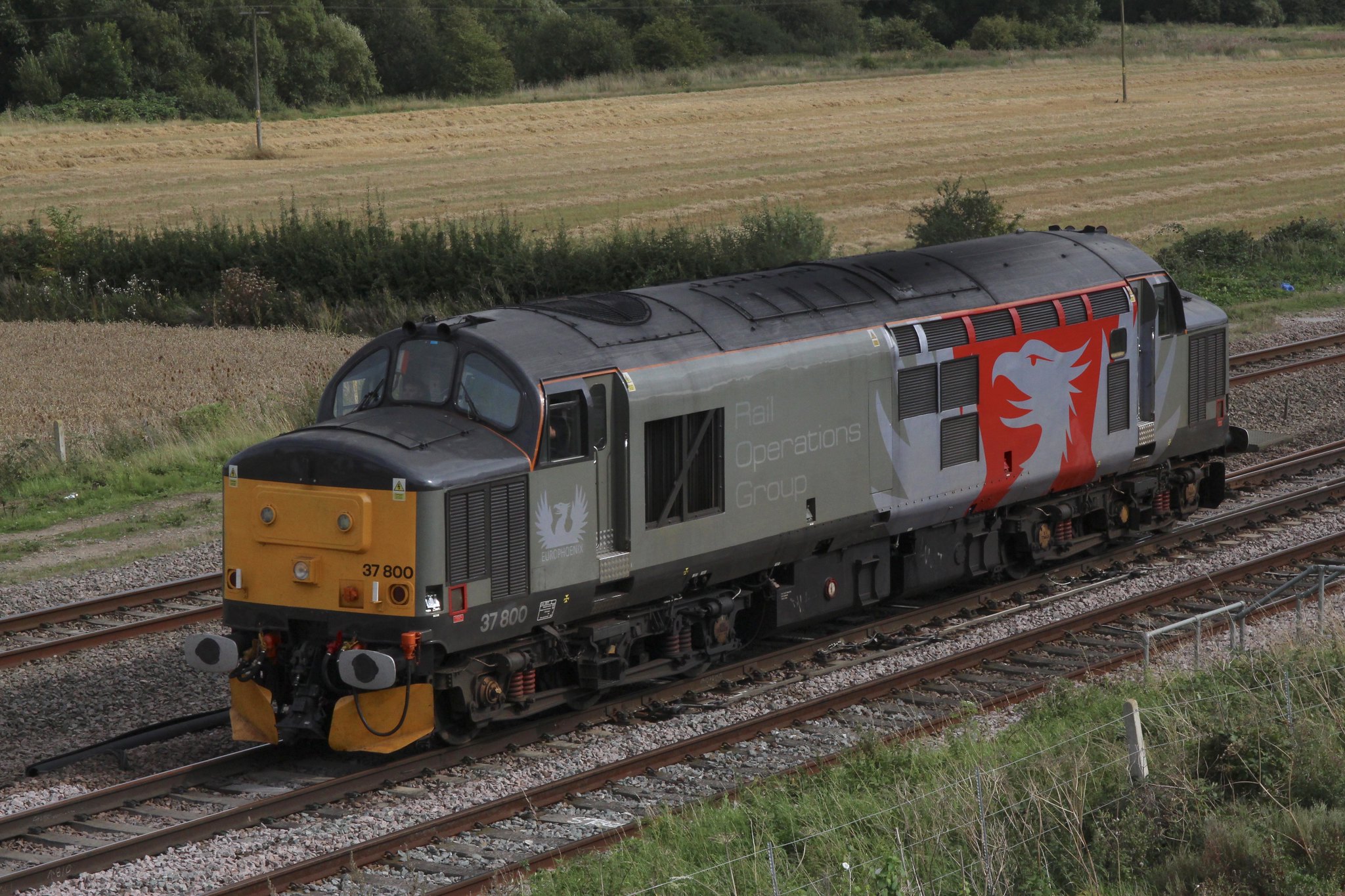 IMG_4838 by Geoffrey Robinson, on Flickr37800 beats its lone path through Harrowden junction on its way back to Leicester from Bletchley running as 0xxx 15:12 BLETCHLEY T.M.D. - 18:14 LEICESTER L.I.P 84 minutes early at 15:42 on Thursday 24 August 2017.
Geoff
-
4
-
-
OK, Geoff. Been a bit busy tonight, will have a look tomorrow.
No rush Ray, whenever you are free.
Thank you.
Geoff
-
Hi Geoff.
Can you post the Sketch that you're having trouble with the turntable stopping short and i'll upload it into my system and see if does the same.
Might take me a bit of time to get it all together as its not been used for some time so don't expect an instant reply.
With regards to powering down the motor, i'm not sure if the Adafruit module can do this, we might have to introduce a relay to remove the power from the adafuit board. I'll look into this as well.
Ray.
Hello Ray,Below is the sketch I am using. I hope it is essentially the one you posted but with a different DCC address of 400 and the values which align the turntable with my approach track. Of course it is always possible that I have inadvertently altered something accidentally when making the the changes I needed, or indeed not changed something I needed to change.Thank you again for giving this so much time and effort.GeoffDCC_Test//////////////////////////////////////////////////////////////////////////////////// DCC Turntable Control Test Routines (Accessory Address 200)#include <DCC_Decoder.h>#include <AccelStepper.h>#include <Wire.h>#include <Adafruit_MotorShield.h>#include "utility/Adafruit_MS_PWMServoDriver.h"//////////////////////////////////////////////////////////////////////////////////////////////////////////////////////////////////////////////////////////////////////////////////////////////////////////////////////////////////////////////////////////////////////////////// Defines and structures//#define kDCC_INTERRUPT 0typedef struct{int address; // Address to respond to}DCCAccessoryAddress;DCCAccessoryAddress gAddresses[1];//////////////////////////////////////////////////////////////////////////////////////////////////////////////////////////////////////////////////////////////////// Adafruit SetupAdafruit_MotorShield AFMStop(0x60); // Default address, no jumpers// Connect stepper with 200 steps per revolution (1.8 degree)// to the M3, M4 terminals (blue,yellow,green,red)Adafruit_StepperMotor *myStepper2 = AFMStop.getStepper(200, 2);// you can change these to SINGLE, DOUBLE, INTERLEAVE or MICROSTEP!// wrapper for the motor! (3200 Microsteps/revolution)void forwardstep2() {myStepper2->onestep(FORWARD, MICROSTEP);}void backwardstep2() {myStepper2->onestep(BACKWARD, MICROSTEP);}// Now we'll wrap the stepper in an AccelStepper objectAccelStepper stepper2(forwardstep2, backwardstep2);//////////////////////////////////////////////////////////////////////////////////////////////////////////////////////////////////////////////////////////////////////////////////////////////////////////////////////////////////////////////////////////////////////////////// Decoder Init//void ConfigureDecoder(){gAddresses[0].address = 400;}//////////////////////////////////////////////////////////////////////////////////////////////////////////////////////////////////////////////////////////////////////////////////////////////////////////////////////////////////////////////////////////////////////////////// Basic accessory packet handler//void BasicAccDecoderPacket_Handler(int address, boolean activate, byte data){// Convert NMRA packet address format to human addressaddress -= 1;address *= 4;address += 1;address += (data & 0x06) >> 1;boolean enable = (data & 0x01) ? 1 : 0;if( address == 400 ){Serial.print("Basic addr: ");Serial.print(address,DEC);Serial.print(" activate: ");Serial.println(enable,DEC);if( enable ){stepper2.moveTo(1106);}else{stepper2.moveTo(2706);}}}//////////////////////////////////////////////////////////////////////////////////////////////////////////////////////////////////////////////////////////////////////////////////////////////////////////////////////////////////////////////////////////////////////////////// Setup//void setup(){Serial.begin(9600);AFMStop.begin(); // Start the shiel//configure pin3 as an input and enable the internal pull-up resistorpinMode(3, INPUT_PULLUP);//read the sensor (open collector type) value into a variableint sensorVal = digitalRead(3);//set stepper motor speed and accelerationstepper2.setMaxSpeed(30.0);stepper2.setAcceleration(20.0);// stepper2.moveTo(800);// if near reference point move awaysensorVal = digitalRead(3);while (sensorVal == LOW) {sensorVal = digitalRead(3);forwardstep2();delay(50);}// step forward to sensor index pointwhile (sensorVal == HIGH) {sensorVal = digitalRead(3);forwardstep2();delay(50);}DCC.SetBasicAccessoryDecoderPacketHandler(BasicAccDecoderPacket_Handler, true);ConfigureDecoder();DCC.SetupDecoder( 0x00, 0x00, kDCC_INTERRUPT );}//////////////////////////////////////////////////////////////////////////////////////////////////////////////////////////////////////////////////////////////////////////////////////////////////////////////////////////////////////////////////////////////////////////////// Main loop//void loop(){static int addr = 0;////////////////////////////////////////////////////////////////// Loop DCC libraryDCC.loop();////////////////////////////////////////////////////////////////// Loop Stepperstepper2.run();}//////////////////////////////////////////////////////////////////////////////////////////////////////////////////////////////////////////////////////////////////////////////////////////////////////////////////////////////////////////////////////////////////////////// -
Hi Geoff,
Try running the turntable test routine with values of say 1400 and 3000. That should make it operate in a different sector to check again for friction.
Ray.
Good morning Ray,
I tried your settings and many others but all gave the same result, when the turntable reverses it stops short. I spent several hours trying to fine tune it but the end result was always that it stopped short when turning in the reverse direction. In the end I was so concerned about the temperature of the motor that I packed up for the evening. I have, as far as I can tell, eliminated any significant friction, any that remains is there for the turntable test which it performs perfectly and consistently. If you have seen my reply to Ian you will have read all this so I apologise for repeating myself.
When the system is shut down I find that the turntable stays nicely in position just with the inertia of the motor so is there a way to build into the programming a command to cut the motor power at each stopping position and then restart it for the next move? I wonder too what would be the effect of setting a second stopping command, as in for a second track, to over come the short stopping on the reverse turn? Alternatively is it practical to have the turntable turn in one direction only?
Sorry for so many questions.
Regards
Geoff
-
Hi Geoff..
sorry to but in, but it seems that your are thinking that what ever sketch loads up in the IDE is what is on the board?
this is not the case.... what is in the IDE is not related to what has been downloaded to the board - its simply the last sketch you had open the last time it was closed down.
Hello Ian,
Yes I sussed that out eventually and I have it sorted now. I have just spent 3 or 4 hours trying Ray's suggested settings and many others and always when the table reverses it stops short of the mark by about 6mm. It responds accurately to the first two command but of course then it is only going forwards but on the third command to return to the original position it stops short. That applies wherever in the circle I try it yet oddly it executes the Turntable Test, oscillating between two positions, perfectly. Anyway I am going to give it a rest for now before the motor catches fire. Even though Ray assured me they run hot when micro stepping I am a little concerned, it is way too hot to touch. As far as my motor is concerned there seems to be sufficient inertia inbuilt to hold the turntable in position, certainly when it is not powered I can drive locos on and off with no issues so I wonder if the programme can be adjusted to cut the power when the table has reached the assigned position.
Geoff
-
Hi Geoff,
Try running the turntable test routine with values of say 1400 and 3000. That should make it operate in a different sector to check again for friction.
Ray.
Hello Ray,
I have sorted the Arduino starting with the turntable test. I waited until I had uploaded the DCC Test and then closed the Turntable Test. I shut down the Arduino software and then restarted and it came up with the DCC Test ready to go.
The turn table always starts from the sensor and on the 'C' command will line up exactly if I put in the right value, around 1106, it will then rotate 180 degrees, value +1600 on the 'T' command and line correctly but when I again send the 'C' command it will stop half a track width, 9mm, short, my layout is EM gauge. I can replicate this with a variety of values around the 1100 and 2700.
I will give your suggested values a go tomorrow if I get the chance. I have checked for friction points and cannot find any so far.
Thank you.
Geoff
Geoff
-
Hi Geoff.
Firstly, the motor does run hot as to use micro stepping it has to be powered continuously. I hope to do a modification using toothed pulley/belts so as not to use micro stepping which would allow the motor to be powered down when not rotating. But i've a lot on at present so to won't happen soon.
Not sure about the power up issue, i thought the arduino retained the last program as well, i'll look into that.
If you're not getting a full 180 degrees rotation it suggests missing steps usually due to friction caused by mis-alignment. Although I'm not sure why you have the values of 1072 and 2704 in the goto commands which may be the reason as they don't subtract to give 1600 or have you adjusted them to over come the friction?
So using my values of 400 and 2000, why don't they add up to 3200? Well they do if you keep counting in the same direction, from 400 to 2000 clockwise is 1600 steps (2000-400) and then from 2000 to 400 clockwise is another 1600 steps (3200-2000+400)
Using your values of 1072 and 2704 we get 2704-1072=1632 and from 2704 to 1072 we get 3200-2704+1072=1568. 1632+1568=3200
Did you try the sketch where the turntable just rotates back an forth between two marks (post 17 Part 5)? Might be worth revisiting this as it will show up any friction in the mechanics.
Ray.
Hello Ray, I am back on dry ground after a week aboard a narrow boat.
Thank you for your reply.
I did run the turntable test and this was working accurately and reliably, however, this test only had the turntable operating in a different sector of the whole circle to that which the table turns through when running the DCC Test.
Your reassurance that the motor will run hot because of the continuous power required foe micro stepping was helpful as I wondered if it was because of a mechanical load on the motor.
I realised the different values should be 1600 apart, the figures I quoted were just where I finished up trying to sort out why it wouldn't make the full 180 deg. turn. I will look to see if I can find any possible friction points in the operating section which might be causing the problem.
When I power up the Arduino it always starts up with the Turntable Test. Should that be over written by the DCC Test?
Once again thank you for your continuing help with this.
Geoff
-
Good evening Ray,
Well after the euphoria of yesterday evening this evening's session has been disappointing. But first the good news. The power connection via the Arduino coax socket and jumper plug works fine so that will be my normal running setup.
The less good news is that although I can set it to align with the approach road on the first command © and rotate through 180deg with the second command (T) and line up nicely, when I send a further © command the motor reverses, not an issue, but stops short by about 3 or 4 rail widths. I have tried many combinations of settings but all to no avail. I suspect it is probably a mechanical issue, too much friction in one direction but I have not yet been able to resolve it.
A couple of other things puzzle me. When I first power up the set up I have to upload the programme before I can use the turntable. Does the Arduino not keep the last operation in its memory ready to use as soon as it is powered up? The motor always starts off rotating anti-clockwise, not an issue, but after the first two commands just turns back and forth through 180 deg. with each command, it never just continues round to the next stop. In its self that is not an issue, I am just curious as to what I should expect. Finally, the motor does seem to get very hot but that might be because of friction in the turntable, oh and when I run a loco on, thus loading the deck, the motor is not able to rotate fully to either position. I think that confirms there to be some significant frictional problems with the turntable.
I have never been very impressed with this turntable kit but at the time it was the only one available for the size I wanted, 50ft if I remember correctly.
I have attached some screen shots to show what it looks like on a Mac and where things end up. Also there are a couple of shots showing the DCC test sketch and the step settings I was using. I understand 180 deg equals 1600 steps so why does the sum of the two settings not equal 3200?
Anyway, we are off on holiday on Saturday so I doubt I will do any more work on it until we get back and then I might have to consider a major rebuild.
Thank you again for all your help. At least we know that the set up works in principle.
Geoff


-
Well done Geoff, glad you got there in the end.
With the power you should be able to insert the Vin link on the Adafruit board and power both boards from either the Arduino power jack or the Adafruit power connector without the USB connection. I say 'should be' as i've never tried it as yet.
Connect the 'reset' wire through a push to make switch to GND and you can then just restart the program should anything get out of sync.
Many thanks for posting your experience with a MacOS setup, I'm sure it will be useful for those using a Mac, me included.
Ray.
Good morning Ray,
Thank you for that, I will have a go at it this evening I hope. I am glad I could make a small contribution to the thread and I will try to post some screen shots to show where all the technical bits finished up on a Mac.
Many thanks.
Geoff
-
Well after burning the midnight oil I have a working turntable, albeit with some mechanical issues I need to think about. It took a little head scratching to get the DCC test to work because again the ' _MS_ ' was required in the preamble and then I struggled for some reason to get programme into the correct place in the 'Libraries'. Anyway it all works nicely from my Digitrax DT402.
It took me some considerable time to get to the appropriate values to line up with the approach track and it is fine now provided I don't allow it to reverse. There is some friction in one direction which I think results in a few steps being missed so I will have to try to resolve that. Otherwise the Arduino is all working just as it should.
My two remaining questions are how can I power the Arduino so that I do not have to have the MacBook hooked up to it? Can I put the 12v supply into the Arduino jack and use the jumper link on the Adafruit shield, or does that work in reverse using the jumper link to power the Arduino from the Adafruit shield?
the second question concerns the reset wire from the DCC interface which is currently not connected to anything. Should it be connected to the Arduino and if so would that be through a switch?
Ray, thank you for the time you have given over to help me with this. I would not have been able to make this work at all without your help and support. Thank you too to Ian and Robin for your input to help me in my struggle with this.
I knew it would not be plain sailing and that was one of the reasons for tackling it, to keep the "little grey cells" exercised. Thank you all, it has been challenging but have enjoyed it.
Geoff


DCC Controlled (PECO) Turntable Project using a Arduino Uno
in DCC Discussion Topics (not questions)
Posted
Ian, I have implemented this and it works fine for me.
Geoff