


readingtype
-
Posts
248 -
Joined
-
Last visited
Content Type
Profiles
Forums
Blogs
Gallery
Events
Exhibition Layout Details
Store
Blog Comments posted by readingtype
-
-
 8 hours ago, Allegheny1600 said:
I take it you're using the OBK108, loco coupling hook? Have you used the wagon couplings, please?
These are H0fine's OBK138. There's also 139 which is for vehicles with a deep bufferbeam or front 'skirt' -- small diesel shunters and railbuses for example.
Yes, I have fitted the wagon couplings too. These have a loop of nicely magnetic steel wire that comes pre-bent. It would be a total pain to make! I thought the cast nickel silver ones were a little OTT (how dreadful to treat wagons as second rate, but there are more of them to work on). The plastic OBK120s fit the bill pretty well and are not that difficult to assemble; there is a central hook/turnbuckle/shaft silhouette laser cut from something vaguely acrylic and either side are triangular reinforcements that vaguely resemble the shackles that are cut from a similar plastic. The assembly work is slotting three 0.4mm n/s wire dowels into holes in the profile and sliding the triangular reinforcements over each side.
You fit them through the convenient hole left by the moulded coupling hook if you are lucky enough to have a wagon made that way; otherwise careful drilling is needed and a 3D printed plug that turns a drilled hole back into a rectangular one (to stop the coupling rotating around its shaft) is available. It is made to look like the flanges above and below the prototype coupling hook. There's a jig (Einbaulehre) that is very helpful. In fact there are two, and the first one I got has lines marking the correct buffer height. Don't put the buffers of anything by Fleischmann or (deeper breath) Märklin against that without knowing what you are doing :-) The second can be fitted with a projecting knitting needle to stab a proffered bufferbeam at the right spot to start drilling.
In theory OBKs should be used with sprung buffers. If you think about this, it gives a couple of mm at most of 'grace' on a sharp curve. Other things may well not be going well for the wagons involved by the time this is needed. I prefer to let the couplings project a little futher; if you fit them as designed you get a lovely close coupling and another mm doesn't really harm the appearance. R1 curves, forget them. OF course there were and are some very sharp curves out there in the world but vehicles are not always coupled together wherever they go ...
Speaking of the appearance, what you can do with both the loco and wagon couplings is completely lose the NEM pocket. Have a look under the vehicle after this has been done and you soon realise how much realism can be gained by taking things away!

(In the photo above the hook should actually be behind the buffer heads rather than in front).
Final point: the plastic is not mega strong and I have already suffered some broken ones (the obvious weak point is the neck where the shaft enters the buffer beam). Etched metal would be more resilient.
-
 1
1
-
-
The running boards, bufferbeams and frames are now basically assembled, so here's a trial assembly of the various parts.
I couldn't resist trial fitting the (turned steel) buffers. The shanks basically fitted straight into the cast holes. That strikes me as pretty clean accurate casting! You can see one of the rear ones isn't quite true.

-
 1
1
-
-
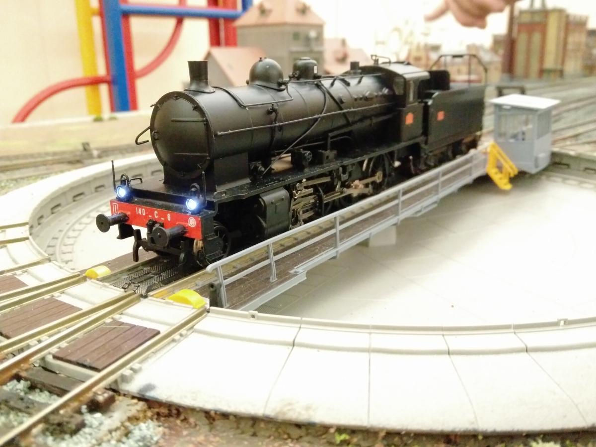
Here it is, still incomplete, on the turntable at Neuhausen after the running session at today's UK FREMO group meeting. Note hand of God breathing life into the brewery in the background. A budget Zimo chip is now in the tender so it can run on FREMO arrangements which are I think exclusively DCC. I wonder if the loco had never run before I got it, as about three hours of test track circuits recently seem to have helped it become a smoother runner. The chip (added just a few days ago) rounds this off.
By the way there's a newly-published French-language publication on the 140 C from Le Train, with the descriptive title 'Les 140 C', and I was lucky to be able to pick up a copy at the French Railways Society Winter Rendezvous earlier this month. It has lots of good pictures (some colour) along with a pretty comprehensive description of the lives and times of these locos.
Ben
-
2
-
 1
1
-
-
A couple of sessions on the club test track show that 1) the front axle needed a bit more play (it now has 1mm of spacing washers each side) and 2) the brake blocks, already filed back, need to get thinner still as they're doing what brake blocks are meant to do. They are also now preventing the front axle from having adequate side play. My approach is to file them at an angle, taking away as little as possible so as to limit the degree to which they are weakened. In the end I have a feeling they may have to be replaced with metal ones that are set further apart -- after all the originals are intended for wheels almost 2mm closer together, even if they do swing side to side a lot.
-
I've worked up first versions of the front and rear guard irons in CAD, based on a copy of the general arrangement drawing in the Eisenbahn Journal special covering the BR 86, II/94 by Manfred Weisbrod and Horst J Obermayer (this can be bought online from the publishers as a digital download, or second hand from Ebay or Abebooks). The drawings looked promising enough to try out in brass. I cut and filed them from thin brass sheet. Here are some pictures showing them fitted. They need a little straightening and centring.
As I have drawn them, the guard irons don't line up with the cutouts for the front carrying wheels because Fleischmann made these up to allow the model to go around R1 radius curves. The real loco has bar frames (like North American steam locos) that run behind the top half of the wheels. Fleischmann's creativity is rather exposed by the finer flanges of the RP25 wheels fitted now. The mudguards are higher than they should be, too. I am pondering whether I can bring these down a bit. With no footplate they're a very characteristic feature of the BR86; checking sources shows they were not part of the original design and the first locos built didn't include them.


-
 1
1
-
-
There is most definitely no protection against buffer locking. You need to be confident that anywhere one or both vehicles coupled with one or two of these go has curves that are not going to cause trouble. The recommendation is to use sprung buffers, but I have (probably through not having spent long enough shunting with these couplings) not yet had trouble on the (fairly short) vans fitted with unsprung ones.
Speaking of tight curves the photo attached shows a situation I think I have only ever previously seen on a model railway. I wonder if that explains the fact there is a partly dismantled coupling lying on the ballast. This is at ÖGEG, Lokpark Ampflwang (Austria).

-
1
-
-

I would be interested to see your FiNe 1/160 layout should it ever venture out. Interesting shape for a layout and interesting choice of scale/standard. Never mind the absence of reverse curves!
-
On 08/04/2019 at 23:21, Barry Ten said:
If you can't repair it, I reckon a Comet pony truck should be a feasible replacement. There's a degree of flexibility about where you solder the washer for the pivot, so you should be able to end up with the correct spacing between the axle and the rest of the chassis.
Wizard Models should be able to supply the relevant part.
Bizarrely enough the missing chunk reappeared -- it had somehow jumped right into the takeaway box where all the things I'd pulled off the loco live.
I've glued it back with ordinary superglue and much to my surprise made a fairly neat job of it. Not very confident it will survive a test run though. Thanks for the tip on the Comet replacement pony truck. For the record this seems the likely candidate: https://www.wizardmodels.ltd/shop/locomotive/ls2/ (pre-WW2 LMS)
-
I'm a lot happier with the running now than I was. As I mentioned, I'm really looking at how well it pulls away and runs at slow speed, because I want to play with it rather than just watch it run. Once travelling at line speed there has been no problem since the contact issue for the driving axles was solved.
This is tempting: ESU's LokSound for the 140.C. Pip pip!
-
Thanks! Well, it was second hand -- but not dirty or showing any sign of wear. Glad to think that my experience doesn't represent the normal standard.
-
I think a few years ago there was a 1:76 scale Faiveley pantograph kit available -- does anyone have any info? I know you could get a Brecknell-Willis one in the early 1990s -- I bought one that never got built, but that's a story from my misspent youth and the chapter is closed ;-)
-
13 hours ago, Titan said:
Aha! Was trying to track one of those down. Thanks a lot.


Fitting nicer couplings to a Roco ÖBB 93
in 0.87
A blog by readingtype in RMweb Blogs
Posted
Final final point, despite being a little delicate these couplings were designed for serious use, specifically at FREMO meetings where running longish trains and doing lots of shunting is important. They couple and uncouple brilliantly if the height is correct and don't snag as much as the conventional NEM design.