


SteveBedding
-
Posts
356 -
Joined
-
Last visited
-
Days Won
1
Content Type
Profiles
Forums
Blogs
Gallery
Events
Exhibition Layout Details
Store
Posts posted by SteveBedding
-
-
Thanks all for your positive comments, and certainly the need to curb the 'enthusiasm' on painting the track has been noted
 I certainly wait until I can get my hands on a wider selection of rolling stock before accepting the track as finished; I suspect the history of Calne may require re-writing such that it was operated by the Midland Railway just prior to WWI... ...hope you're watching this Mark
Good advice on the back-to-back and guages Don. I think I've identified the pinching on the turnout; there are two very closely sequenced turnouts leading to the milk bays and cattle docks and I had not been able to easily seperate them - in constructing them, I partially tacked the rail in the middle to give the overal geometry and it looks like I'd forgotten to fully set it in the correct position. Anyway, although not 100% confident that its fully right, I may just have cuffed it as the loco doesn't derail now
 . I think I need to keep a snagging list handy to keep track of all the minor snafus that occur as I progress.
Pete, you asked about the use of the copper-clad sleeper? I vaguely remembered wittering on about my thoughts on this pereviously and looking back, I found that I had outlined these here (frightenly, this was over a year ago
 !!). Anyway, to recap: I've replaced a total of 8 of the plastic sleepers with pcb strips (3 alternate ones under the crossing centered on the knuckle, then 2 where the crossing joins with the blade, one further to support the blade and help form its shape [added since the original thoughts last year], and lastly one either side of the moving tie-bar to make the entry rigid and support the joggles) - see below:
Here's the same turnout with the track laid...

... I've found that this method makes the turnout quite robust (much more so that the first 2 I built on the first board where I used far fewer pcb sleepers) and the geometry relies on the soldered joints rather than the easitrac chairs. This so far has been a lot easier to fettle to get right than trying to move the plastic parts and I've left gluing the chairs to be the last task once I've test the turnout. (Oops - Note to self - need to finish the chairs on this turnout
) Although I've done some initial cleaning of the sleepers, this picture shows the nasty state that the working surface has degenerated to. Looking back, I suspect I used too much PVA in fixing the sleepers, and too much solder & flux on the rails and this has made the job of cleaning that much more painful! Now you can see why I'm desperate to paint the track to hide this...Just for interest, the numbers in pencil below the turnout are a reminder to me of which 'chairs' to use when threading them onto the rail before fitting; I'm sure that there are really technical terms/names for the differnt types of chairs, but I like simple and so have called them: 1 - blade chair, 2 - normal chair, and 3 - check rail chair, and these numbers reflect the order from the top that they appear on the easitrac spue (below).

Lastly, while SWMBO wasn't looking last night, the centre board did a swift 180, and work has commenced on the track on the last board. First task is to set the sleepers for the turnouts and this is almost done (it would have been completed by now, but Sunday afternoon has been sidetracked indulging in another passion of mine - food - watching the recorded final episodes of Masterchef for some inspiration
 !)
!)
Nice and simple to complete, so no excuse for excessive delays...
Back soon,
-
 3
3
-
-
Thanks to everyone for your continued interest and perseverance with my prolonged absence - things are on a bit of a roll at the moment some significant progress is being achieved
Following on from the mid-week 'newsflash' and the euphoria of the first simple test runs, I have throttled back with a more structured approach to the testing. The LED driver for the control panel has returned from the electronic 'hospital', and is now fully functional - somehow I had managed to cook the surface mounted MOSFETs (translated - extremely small fiddley transistor thingys) and this was causing multiple illuminations - in my defence it was 30 years ago I trained in electronics and these weren't arround then! Anyway, the control panel now works as planned and with the PC interface, the MERG CBUS system was surprisingly simple to configure and program.
The concept of the panel is to simply push the button for where you want to go, and the various turnouts required to get there will be selected; the yellow LEDs give a visual indication that the point motor has operated as requested.

Now with the turnouts operating simply (I'd alluded earlier to the 'problems' with easily testing the Cobalt motors), it was a now a case of running the trusty Class 24 and test wagon (my first {unfinished} 2mm chassis - no body, weight, or couplings
) back and forth over each part of the layout, keeping a beady eye on the performance. Although I'd previously done free-wheeling testing on most of the point-work, a couple of new 'issues' were found in those areas un-tested; one tie-bar operation is 'sticky' in one throw direction - easily fixed?, and there appears to be a significant derailing problem through another - there appears to be a pinching effect which can be seen visually but gauges out correctly  !
!I was keen to get a coat of paint on the trackwork (to hide my ineptitude) but I'll hold off on this for a while until I can resolve these 2 issues! I'll try and borrow some additional rolling stock to do some more thorough operational testing before accepting the trackwork on these 2 boards - bit of a blow as I wanted to get cracking on with the last board...
And finally, although I was previously able to get the loco to run the length of the 'main-line' the track work at the board joint had been re-aligned with a pair of pliers until it worked; this has now been properly fixed.

Having taken the picture of the joint, it actually looks quite good! I've been cursing it no end as to the finger test and visual inspection it appears to be a real bodge yet there have been no problems or issues with the running behaviour at a quite a range of speeds?
That's all for the moment; be back soon...
-
6
-
-
x-x-x-x-x-x NEWSFLASH x-x-x-x-x-x
It Lives!!!!
Just connected Boards 2 & 3 together for the first time (since the original carpentry...) and just had to have a quick test run... ...the trusty '24 ran over the board joint without a hitch on the mainline - the sidings/runaround needs to be reworked as a rail got bent in storage
 )
)
Not much of a picture (I was kneeling backwards over the desk to get as much of a view as possible) and it shows the messy wiring 'hidden' through the hatch into the kitchen
But who cares - the layout worked! The points operated right first time and the train ran when told - what more could I ask for?Anyway, still lots of fettling to do (and the control panel LED driver comes back from the electronic hospital tonight) so I'd better get back to it. Back soon with a fuller update...
-
8
-
-
So when will the Calne layout be ready for the Calne Show?
Geoff Endacott
Not before Jan '14 - and even then it'll be a work in progress... ...and probably only as a static diaorama if I don't get on with the rolling stock soon!
-
It does look impressive. it is almost a shame not to display the layout upside down.

I had thought about doing away with the skirt and puttling an angled mirror underneath...
-
Thanks Pete - its good to be back. This semi-retirement business has its advantages in that I have been able to crack on with the layout, but at some time I really do need to get a job - its a tough choice 1) play trains, or 2) live? It's not your fault you suffered a 'premature posting', I took so long in typing up the last missive (and regularly using the preview ) that it seems to have taken a partially complete entry brfore I'd finished
Jerry, there was more than one occaision when the whole control system nearly got a 'digitus impudicus'!!! The option of parallel switches on the sides of each board became very appealing...
Tee hee Natalie
even with the 2 wire dcc, there are over 70 droppers on Board 2 alone. Seriously, the back of the control panel looks complex as it uses 56 LEDs, and 39 toggle or push-button switch inputs; these have to wired up in a matrix of rows and columns (on matrix each for the LEDs and switches). The end result is that the CBUS output of this panel comes out as 2 wires which is all that needs to be connected between the board.Thanks for the tip Don, I'd been using the single digit technique previously unlil Mitzi sugested gravity - so obvious really! Since then I raise one end of the board by about 1" - 1.5" (about 1 in 48 to 1 in 32) and watch 'dem wagons roll' (Yee haaa). The wagon only needs a couple of inches to get up some speed and then the Mk1 eyball tracks it for the (hopefully absent) bounce as it passes through the pointwork. Several pinch-points have been found when the wagon slowed down...
A bit more on the Control Panel. I was very fortunate that another member of the Oxford group had access to a laser cutter; a simplified line drawing of the layout was produced and etched to produce a representative schematic of the layout - even the holes for LEDs and switches were cut in plastic to make life really easy. Outlines of the major structures (Goods shed, Harris Factory, and the platforms) were marked on the plan to ease visual orientation. The final design incorporated switches and red/green LEds represent future signalin options, and the box in the lower left corner is to cater for the potoential expansion further down the line to include Black Dog Halt - what's wrong with 22'-24' long layout anyway?

The way in which the pushbuttons have been placed is to enable a rudimentary form of route selection rather than direct point control; with the exception of the 2 crossovers (which switch between straight or crossing) each of the push-buttons represents a destination ie one of the sidings. For example, to get an arriving train to the Harris Factory, first select the approach crossover to get off the 'main' line into the sidings, then select Siding 4 (south side of the cattle dock) leading to the Harris sidings, and then finally select the route into the factory itself. What happens is that (the cross over being faily self-explantory) when Siding 4 is selected, all of the turnouts downstream (back to the crossover) are set straight up to Siding 4 allowing a clear run. I deliberately split the Harris sidings from the main sidings to enable independant shunting in this area,and to have a (future) gate controlled entrance to the private sidings.
Just as a matter of interest, I've included a small section of the CBUS configuration matrix i've been working on to show how each pushbutton input (lefthand column) causes the many point drivers to react...

...simple isn't it
As you may note, I have a lot of potential ideas, but not yet got any detailed plans to deliver them...

-
2
-
-
Good grief! Has it really been nearly 4 months since I posted any updates
I could have sworn it was only a few weeks!!!!!Well, I had decided to focus on actually getting things done (rather than planning/pontificating/procrastinating) but even with keeping my focus on the layout, progress has been 'steady' rather than like 'greased lighting'. I still cannot help but jump about between projects - baseboards, partially completed wagons, control system, and initial steps in loco chassis construction, and the occaisional show, but overall I can report there has been some significant steps in the right direction
Firstly, all of the trackwork on Board 2 has been completed up to the joint with board 3; the dilema over the 'correct' sleepering has been put rest - life's too short for absolute perfection! I did rework the sleepers under the crossover in the station to be more 'prototypical' as the trackwork was incomplete and easily corrected. I have done a 'first-pass' on fettling the pointwork to ensure smooth running using a simple unweighted 2mm chassis; this did identify several areas where despite the use of guages there were noticable pinch points. When I ran my trusty Class 24 over the lot (with an extremely Heath-Robinson wiring lash-up) it experienced no noticable problems and gave reassurance that all was heading in the right direction.

Once I'm fully satified that the trackwork is running error free, I'll put in the last few cosmetic chairs arround the Easitrac point work and give the rails a damn good spray of a nice dirty brown. I was not impressed in how long it took me to clean up the soldering on the copper clad sleepers - it was a job that needed to be done, but it really did reinforce the understanding of the 2 ft rule of what level of '(im)perfection' can be seen
This leads to another chicken and egg situation - can't fit the point motors until the track is laid, and can't easily test the track (electrifying the frogs) until the point motors and micro-switches have been fitted... This seemed like a good point to finalise the plans for the track control system; that and the fact that the Oxford 2mm Group layout had reached the point of rewiring and implementing their control system, meant that now was a good point to focus on those wiggly amp things. Right from the start, I had decided that I wanted the control of the track to be seperate from the control of the loco's and I really wanted to fulfil a long term aspiration to implement the posibility of some form of computer control or other 'technological' solution; these requirements amd potential solutions were:
- Loco control:
- 'Cab control' for individual locos,
- Concurrent loco running (regular service plus local shunting),
- DCC or switched DC?
[*]Track control
- Seperate from loco control,
- Physical switch (or push-button) operation for points,
- Positive indication of point positions,
- Seperate DCC accessory bus or MERG CBUS?
[*]General:
- Ability to operate layout from front or rear,
- PC Interface (loco & track control) - JMRI,
- Automation?
- 'Cab control' for individual locos,
Over the time it has taken to get this far in the layout build, and from experience gained from working or building other layouts, the decison was pretty much made in favour of the Lenz system for the DCC loco control, and the MERG CBUS system for the track (and eventually signal control).

I have heard many mixed comments about MERG kits, but I have to say that my own experience of them has been extremely positive; with one exception, I have always found them to be straightforward to make and work first time - the exception was due to my fault in 'cooking' some of the surface mounting components, but in my defence, this was the first time I had ever actually worked with that type of component.

I couldn't help myself in knocking up a simple test rig to learn how the CBUS system would work - thankfully, the PC interface is quite straightforward worked easily - I did not want to face programming each board using the switches
I've not yet fully programmed the system to fully operate the layout, but so far have created a simple set of instructions to carryout testing of the track work. Once tested and proven to work (with the exception of the control panel LED driver which has had to got to the electronic hospital - thank you Howard to recover from my ham-fisted soldering) the CBUS modules have been fitted to Board 2.

I have yet to connect up the feedback/point position detection wires (orange twisted pairs) but this will be done quickly once I have got the point motors working the 'right' way round; the plan is to set the default condition to 'straight' when the control signal is off, and conversly to 'diverging' when the control signal is on. This will simplify the final programming/configuration - when I finally get there... I had originally planned on standardising on Tortoise Motors but due to the precise positioning of two of the turnouts, I have had to use several Cobalt motors as they have a slightly smaller physical footprint. Usual disclamer here - although the Cobalts are slightly more expensive so far I have found them to be very good - somewhat slower in operation than the Tortoise for the same voltage, and noticably quieter; the downside is that you cannot 'manually' throw the arm to operate the turnout (needed for testing), they only work under power. Once the final wiring of the point detection is done, I am going to fit plywood covers over the sections of the baseboard where the CBUS modules are mounted - they are too fragile, particlaly the heatsinks, to be left unprotected.
Connectivity between the boards has been addressed with a uniform structure for the wiring; DCC track power is fed via RCA phono connections, 12v dc via standard laptop power jacks, XpressNet (for handsets) via 5 pin DIN plugs (standard connectors for Lenz), and the CBUS network uses normal network RJ45 connections. It may seem that a lot of connectors have used but this was to ensure that it was imposible to incorrectly connect the various circuits. The USB connector allows for PC connectivity direct to the CBUS system, and additional XpressNet connectors have been included to allow for the PC to connect to the DCC system.


As to the control panel itself, it was simple in concept but a PITA in practice (now I understand why my daughter calls me this, though I did have to Google it.
 )! Firstly, the switches and LEDs had to be big enough to cope with 'playmobile' scale fingers and potentially deteriorating eyesight, and would be nice to be a 'feature' of the layout. Secondly, the layout has to be operated from either front or rear so the panel had to be capable of mounting on either side and keep the correct orientation.

The 'funny' shape allows the panel to slope when fitted to either the front or rear of the layout - and to keep SWMBO happy, has rubber feet underneath to protect the dining room table... ...and now the messy bit:

After seeing this, my son said I had OCD! ...it looks like a right ######-muddle but it works!
Well now I just need to rearrange the dining room to loose the table, so the 2 boards can be assembled on their legs and the trackwork can be properly tested...
"I'll be back..."
(....hopefully before July?)
-
4
- Loco control:
-
Good grief! Has it really been nearly 4 months since I posted any updates
I could have sworn it was only a few weeks!!!!!Oops - I seem to have taken so long in writing this up it has double posted ! See below for full details...
-
2
-
-
Wow that looks FUN!
looking forward to more reports about using this Steve.. what CNC software are you going to use?Tom
Not 100% certain at this point - the kit suggests either WinPC-NC or Mach3 and initial thoughts are leaning towards the latter. However, until I get 'test' or evaluation versions of the software I've not got off the fence on this decision... ...factors will obviously relate to cost, and as this will be shared asset, the views of others, and the portability of the software.
Once the hardware is finished, then I'll start testing how it works - I'll need something at that point to make the toy critically important tool do what it's supposed to, and I believe that Mach3 does offer a 30day trial period (and manuals in English...) - that may be a guiding factor, but WinPC-NC is cheaper...
-
Thanks for the continued interest - it acts as a spur to keep going when all else around is providing distractions and 'justifications' for doing other things...
To answer the questions raised...
NickB,
I'm afraid it's nothing sophisticated on the tie-bar front, just a simple moving sleeper arrangement. It is almost the same as done on the crossover on Board 3 (see here) but I've shortened the top layer of brass strip to be more representative of a chair plate and rather than placing the tie-bar sleeper between two existing ones, I've replaced one of the fixed sleeper with a moving one... Probably a bit crude and simplistic (I can identify with that
) but it seems to work and is within my capabilities and skill levels.I'll post some pictures in a bit when I get board back up and have made a working set that is fit for public consumption...
(Bad)Rich, Pete, et al,
Some may well remember my musings and aspirations on a certain modification to my little mill?

Well, a couple of months ago, a certain young lady of this parish, who's model engineering skills are quite phenomenal, suggested that this dream could be achieved as a group effort if too much for one. Well to cut a long story short, a small (but heavy) package was passed to me for playing with...

The contents are very straight forward, steppa-motors, mounting plates (very nicely made!), control circuits, and all the necessary, fixings, cables, switches, etc to complete the project. The kit itself come from a German firm (Usovo) and well reflects the engineering reputation of that country.

Contents of box - a very nicely put together 'kit' (I apologise for the focus of a couple of the photos - I think I'd been playing with the camera settings again... ...well either that or the G&T may have had a slight effect
 ). The instructions were obviously not written in English originally, and there are some interesting translations, but the text is backed up by very clear illustrations and makes the steps simple and clear enough to follow.
The mill itself brakes down very cleanly, and although some parts are no longer needed, the conversion is very good at identifying and reusing many of the smaller components. My only comment here (and being really picky to even find this small observation) was that the clever re-use of washers was perhaps too clever, and I will add some additional ones to shafts when finalised.
The actual conversion could probably be done in a single day - it really was that simple! But it has taken me several weeks through a) procrastination!, B) being too scared to make a dogs dinner of it!, c) (my favourite excuse) being thorough and clear about each step (see a) & b ) above), and d) using very slow curing Araldite rather than the rapid version...
...despite all the delays, I have finally reached the point where I can carry out a practice assembly, and very pleasingly, it all fitted! More importantly, things moved when knobs were twiddled...


There is still quite a bit to do to finish off the project, but this is almost entirely electrical related and fairly straight forward - it should only take a couple of hours and then full testing can take place. However, this will have to wait for a couple of weeks as other (less exciting) activities are looming to fill my days. One last observation about the conversion, is that it has improved the usability of the mill; the MF-70 is a very good piece of kit, but the usable working area (along the X & Y axis) is quite limited - the way in which the CNC conversion is carried out has effectively added 15-20mm all round the work table, increasing the available working area considerably.
-
5
-
-
Kev
Thanks for the prompt - all has been too quiet (?) here for a while - modelling has not exactly stopped but has been spread very thin over too many projects!!! Also I've not got to grips with the new format of RMWeb yet (the office IT is too obsolete & slow to be practical to view it when at work) but I hope to get seriously back on-line soon... Some of the minor interruptions/distractions/projects have included:
1) Designing & building the MERG CBUS control system for the Oxford 2mm group layout - should have been simple but its 30 years since I played with the the wiggly amps at component level....2) Making some minor (?) modifications to my mill - more on this later 'cos if it works I'll have a big smug grin...3) Helping Mark and Jerry exhibit WE and Highbury Colliery...4) Too many shows and the 2mm AGM to go to...5) ...and finally Smokey did get a look in... (it did suffer from a serious loss of mojo after it was discretely pointed out that I laid the turnout sleepers incorrectly for GWR prototype track - I wish he'd spotted it earlier! That said I now know more about sleepering than I think I ever wanted to know; but after careful consideration and chewing of the fat, I decided that it was too late to do anything about it!)
Not one of my better photo's but a quick one with phone to prove that things are moving forward! Easitrac is supposed to be quick & simple but I still take several hours to get about 12-18" done. However I have also got the blades done on 4 of the 9 points on the board (2 will need to be redone but they sort of work at the moment
)*** Since this photo was taken a couple of weeks ago, most of the sidings have been laid and I've started on wiring up the droppers - hopefully a train will run soon - for test purposes of course, not playing***Oh yes, career transition courses & retraining, and looking for a new job, home etc as I leave the RAF in about 5 months after 20 odd years.. However, I do have a couple of months of 'gardening leave' when I can hopefully finish off this board and publish some photo's and greater details
:) Watch this space for progress over the next few weeks/months/yearsCheers,
PS - the gratuitous train shot...

... a nice pose of a GWR 8750 (later 57xx) in Hawkesworth's post '42 Austerity livery taken at Didcot in July this year.,
-
4
-
-
Fast approaching one year into the project and I'm very aware that things appear to have dropped off over the past several months
 , however, albeit extremely slowly, I have been making quite a bit of progress on the track laying on Board 2. The slow and tedious process of pre-placing the etched brass chair plates on the pcb sleepers has paid off and made the laying of the rails quite straight forward; that said, straight forward or not, my production rate can only be described as less than snail pace
  . The laying of the straight stock rail across the first 4 right hand points took almost 30 hours to produce about 28.5" of rail (Note: I do mean rail rather than track as this was only for one side!) which equates to a rate of less than 1" per hour - as I said, slower than a snail .
I beleive it was worth taking the time to do this (and get it right - I hope) as this rail effectively becomes the datum line for the remainder of the track on this board. I also added to the complexity of getting the rail straight by including joggles in the track which although cannot be seen from a distance, did make getting a true straight alignment quite a challenge. There is still the cross-over to do, and the point into the goods shed, but this represents the majority of the complex work; thanks to the simplicity of Easitrac, the four full length sidings should be completed in a few hours, though with the dining room been reclaimed by SWMBO, I may have to wait a week or so before this can happen
 .
.
The siding (coloured with yellow highlight) was the main cattle dock line and when the station track was relaid with bull head rail, this siding was left in the original flat bottom rail as most of lts length was embedded in concrete for ease of cleaning. I've watched other attempts to represent this effect with great interest and having seen the 'challenges' that it has caused, I'm approaching my attempt with great trepidation...
With the straight stock rail laid, I placed all of the crossing assemblies in the correct locations. These were soldered into place and although the plastic chairs had been fitted they have not been glued down; this allows for easy 'tweaking' of the point/crossing once the track work is completed. However, great care must be taken this way not to damage or knock off the chairs when clumsily wielding the soldering iron and fettling file... One idea I had for making these points was not to cut the strips of brass used to construct the crossing assemblies back to the rail edge; this time I left a short length (about 0.75mm) proud of the rail to represent the chair plate at these locations. Having pre-tined the sleepers, it was a very simple matter to lightly solder these strips down, without affecting the joint to the rail, so fixing the crossing assembly more securely than just leaving it 'floating' (this appeared to work and I was feeling quite pleased with myself here
)

The very cruel close-ups really do show just how much cleaning up of the soldering I have to do! This does bring home just how much difference there is between soldering of electrical/electronic equipment and circuits and the making of models and track work... Hey hum, I suppose that this will keep me out of mischief for a number of hours over the next few weeks
But once that's done and the rails and sleepers are painted, I'm sure no one will notice how cack-handed the production was....I've been putting off laying the sleepers for the point leading to the goods shed, as I was aware that the location of the 'moving sleeper' tie-bar was going to be a very close fit to the adjacent point forming part of the crossover. Now that constraints can be clearly seen (below) I can position and fix the sleepers to complete this point. In this case, my lack of ability/experience with Templot is very clear in that 'as-drawn' positioning of the sleepers will have to be adapted when it comes to the 'as-fitted' positions... With a little creative adjustment to the spacings of the sleepers, and I'm quite confident that it will all come together and work as planned (must think positive here...)

Well thats all the current progress to-date; I think things are coming together quite nicely and now that the motivation and drive has returned I hope to be able to report a steady stream of steps in the right direction....
PS No gratuitous photos of real trains this time - but I'm off to Didcot tomorrow so watch out for the next instalment!
-
4
-
-
Slow but steady progress; well, this is what I'd like to report but there has been far too much "slow" and not enough "progress" for my liking - and it certainly has not been steady!
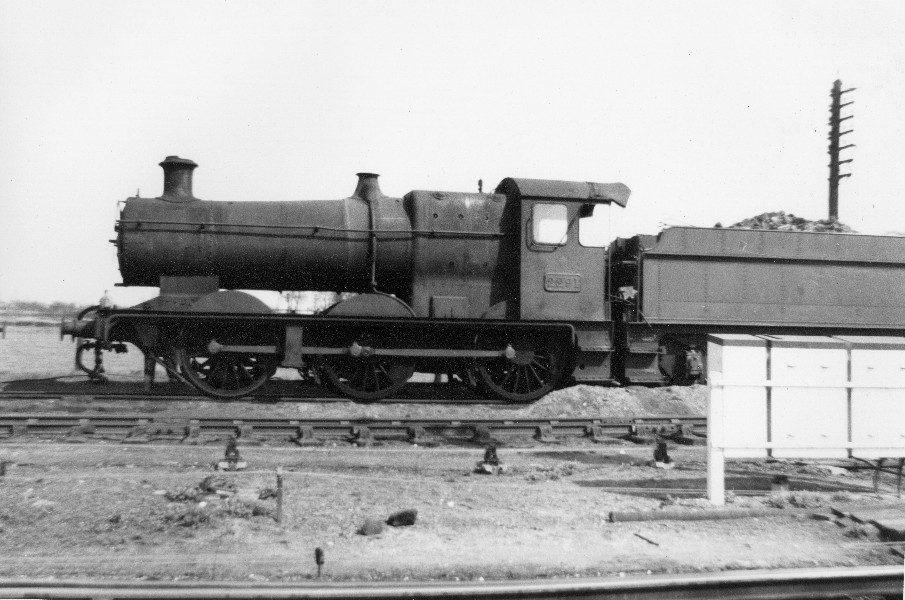
The good intentions (I managed to reclaim the dining room, and started to lay out the boards and tools etc...) were yet again interrupted by RW events. However, arranging a 60th birthday party down in Devon gave me an excuse for another sortie to Buckfastleigh for a little bit more 'research'...Fortunately, it was the turn of a 45xx to be in steam on this occasion, which afforded me lots of opportunities to get pictures of the running gear and other details:


Like the Collett 2251 earlier in the year it was in BR livery (and far too shiny!), but although I'd like to see it in unlined black (GWR Austerity), it's good enough for the overall appearance.
Back to the layout. Work has focussed on fitting the chair plates on the copper-clad/pcb sleeper - so far I've done about 280 individual chairs and there are about another 140 to go! They are best done in batches of about 20-24 (4 chairs per sleeper) before the wrists start wanting to find a chainsaw! The horribly cruel photo below shows the placement of the etched brass chair plates; cleaning the sleepers afterwards has caused a fair degree of smudging of the track plan, but at this stage this becomes irrelevant as it will all be hidden by the ballast and a liberal dosing of 'Sleeper Grime'...

Another advantage of the use of the Templot plan stuck to the board is that 'engineering annotations' (aka the pencil scribbles...) can be added to the diagram to provide a sanity check/count of the numbers and types of the plastic Easitrac chairs
The actual chair plates used are from the Versaline system; previously I'd used just the standard ones, but following the 2mm Expo last month, I'd gotten hold of several sets of the etches for points. The purists may, on studying the placement of the chairs in the sleepers, observe that they may not be 100% prototypical but I'm most definitely going to apply the 2ft rule here and stick to the view that they are only there to give an 'appearance' of chairs... 
Each of the point etches should cater for 1 point, but because I'm only using a selection of pcb sleepers in the Easitrac point, I've found that by careful selection and use of specific plates (and giving the instructions a stiff ignoring!), I have been able to get sufficient 'usable' plates for 3 points per etc. (Is this taking economy too far?)
-
1
-
-
Actually the 2251 body is to 1:148, so the scale driving wheel diamater would be 10.64mm. But rounding up is a dangerous thing here. The O/D over the flange will then be 11.5mm, definitely more than the prorotype, and whether that will fit inside the splashers I do not know (not owning the aorementioned loco).
Good points Chris - I always quite happy to have my assumptions shot down... If it's any help, I've just quickly disassembled a Peco Collett and the wheels appear to be 10.7mm with a flange O/D of just over 11.8mm.
Hacking 1.5 from the rear of the etch will impinge upon the rear spacer, which has specifically been positioned to match the Peco location hole. So really not quite as easy as it sounds.
Nothing is ever as easy as I would hope it to be...
-
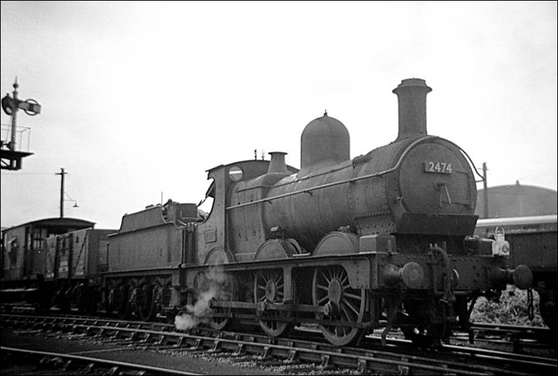
Just for reference, both the Dean Goods and the Collett 2251 used 5' 2" 16-spoke driving wheels on 7'3" - 8'3" spacings; this diameter equates to 10.36mm at 2mm/ft, which is closer to the 10.5mm association drivers.
The only real difference (that would be noticeable in 2mm) would be the front and rear 'over-hangs' which were 4'9" & 4'0 for the Dean and 6'6" & 4'9" for the 2251. If the chassis was sized for the 2251, it would be a matter of fettling about 3.5mm off the front and 1.5mm from the rear...
I don't have any dimensions for the positioning of the front guard irons, but looking at the pictures and diagrams in Russell's Pictorial Record of Great Western Engines, I would consider that, relative to the leading drivers, the locations of the guard irons are not too far dissimilar for both locos. (OK, the purists may wince at this, but it could be a pragmatic compromise...).
-
Very nice & simple - I've immediately used it to add the 'standard' GWR drivers for a quick reference. Cheers Pixie
-
The 57XX, 14XX and 03 are all very close now...
This is sounding good
My attempts at a 57xx frame have not been as successful as I would like and certainly not as detailed as yours - so hopefully the 'very close' is really very close... As to the 2251, that's going to be an even greater appeal, especially if it can be adapted for the 'eventual' Dean goods......There are plans for more.
What would these be? Can I hope for chassis for the Ixion Manor, and future offerings such as the Farish WD and the Dapol Hall?
-
Thanks everyone for the ongoing encouragement; and especial thanks to John for the box - it will greatly add to the character of the layout.
Well, to paraphrase British Rail "I'm getting there...", the chaotic times of RW family commitments are just about winding up now and so some serious modelling time is owed to me. That said, even these interruptions have been enjoyable/useful in that a trip to visit family in Lancashire just happened to coincide with the 2mm Association Expo in Keighley, and Fathers Day was focused around a very fine lunch on the Avon Valley Railway....
(there seems to be a bit of common theme emerging here with trains and food  )
)Anyway, I have now managed to replenish my stock of rail and other essential building supplies and so can crack on with progressing the track work - I learnt a lot at the Expo on simple methods to make 'joggles' - very timely and will be put straight into practice. I did however manage to acquire one or two small distractions (coach bogies, wagon kits, and very nice etch for a class 45xx chassis) which will probably conspire to derail the best plans. Oh well, they will all contribute towards the eventual final layout...
Thanks again and hopefully my next post may actually show progress rather than 'excuses' for its lack...
-
1
-
-
Gents, thanks for the concern; all is well but a small outbreak of 'loss of mojo' occurred at the same time as some seriously busy RW intervention/interference
 Is it really nearly 10 weeks since I made any progress on the layout !!!
However, all was not lost, as despite the annoying interruptions, some important research has been achieved
Firstly, pasties and cider on the South Devon Railway...
...a shame about the livery, but you can't go far wrong with a Collett 2251 Class...
...a good opportunity for a study of MOGOs, DAMO A, and a FRUIT D...


...just waiting for Dapol's future Hall

...and last but not least, a tanker with great family significance.

Secondly, a trip to the Watercress Line for the fine dining on the Watercress Belle...

...OK, so it's not GWR, but SR is just as acceptable when there is good food involved...

...Don't let SWMBO claim that I don't get her flowers !...
...but don't tell her that all the ladies were given them when they arrived
...and I didn't get to this size by avoiding too many 6 course meals

and Thirdly, a quick trip to Bucks for a cream tea on the Chinnor and Princess Risborough line...
...ah, back to GWR...


(for any Weight-Watchers out there - this little lot is apparently equivalent of just over 50 Pro-points - that's more than a days food or a weeks snack/treat allocation - OUCH!)
...and when you reach the end of the line, thy really do mean it here!

More on the up side, visiting the RMweb day in Taunton, and getting back to driving Witney Euston at both the Oxford show (actually in Witney) and at Railex last weekend, has given the juices a damn good stirring and I'm getting to point where the mojo is getting back to normal levels!!!
More to follow soon...
-
2
-
-
...The large house on top of the rise behind the printing works ( look at earlier posts) is now the Con Club. This is the house where Stannier lived while he was Ch Eng. He would have walked 2 minutes round the corner from his house and onto an early train for Chippenham, and change for the Works at "Piggy Hill".
Just imagine how "on the ball" the Station Master would have had to have been with the Ch Eng using the Station twice a day!...
What a lovely gem of information - though I suspect that he would have moved to somewhere in the Midlands by the time I'm looking at...
I didn't think Stanier was a GWR Ch Eng, though he worked under Churchward and Collett, eventually as the Works Manager at Swindon. Even so, that should have been enough for the staff at Calne and Chippenham to be on their toes whenever he was passing through.
-
1
-
-
Pete, I'm sure that a third set is planned and there will be at least one blue engine, a red one and some green ones. These will all have smiling faces.

Now there's an idea - Sodor in Wiltshire... That'll be a fourth option for rolling stock, and one that I think will get SWMBO's approval
It would even be appropriate to run "D7101 Bear The Hymek Diesel" and that was blue - should keep Pete happy...-
1
-
-
Perhaps a PM to Mike the Stationmaster might bring forth more info.
Excellent suggestion Nick, and one I've promptly acted on (well it would have been a bit quicker, but I couldn't access RMweb for much of the past 48hours - some network issues I suspect
). Mike very kindly, and promptly, answered confirming your statement on the reasoning behind the change in the route restriction designation, and then gave a nice, simple, and comprehensible explanation of what the 'hammer blow' effect was...
...the whole 57XX/8750 group, except for the condenser equipped 9700-10, were altered from 'Blue' route restriction to 'Yellow' in 1950 (regret I can't give a more exact date) as it had been found that they had a very low hammer-blow effect. What I don't know is how long it actually took to alter the markings on the locos but presumably - as it was normal practice at that time - the change was implemented by written Instruction and the operational impact would have been fairly immediate.
There seems to have been quite a movement of 57XX around depots in August of that year so that might be a clue to the date of the change. Hope that helps.
...In very simple terms (according to my simplistic understanding of it) a steam loco puts weight down on the track and structures in two ways The first of these is the direct vertical loading of what it weighs - e.g an original 57XX plonks 47t 10cwt onto the track spread over its 6 wheels. The second lot of weight is the dynamic loading (I think it used to be called reciprocating weight or something like that) which basically is the extra load thrown onto the driving axle by the action of the pistons and connecting rods as it is translated from reciprocating movement to rotational movement on the driving axle. This weight is uneven because there are only a limited number of cylinders so to cancel some of that unevenness the wheels are fitted with balance weights. But those weights cannot totally eliminate the imbalance and what isn't balanced comes out at the wheel/rail interface as hammer blow.
Hammer blow is worst on 2 cylinder locos, a bit better on 3 cylinder locos and better stiil - or rather more evenly distributed round the circle represented by the wheel - on 4 cylinder locos but it also depends on the way the pistons are set in relation to each other. So less hammer blow equals less bashing of the track from the reciprocating movement. Simply summed up hammer blow magnifies the loading from the weight of the loco, and it does it unevenly.
Yet another piece of information gathered; whilst not strictly relevant to the period that the planned (...and domestically 'authorised'...) Smokey Bacon is set, it may well come in handy for a 'possible' second set of rolling stock that would take the Calne Branch through the BR steam era... ...but that's for another day
-
1
-
-
I may be wrong, but I don't think anyone has mentioned that the 57XXs were all reclassified as yellow route colour (except 9700-10) in 1950. Perhaps the folk on the Calne branch were just very forward-thinking?
Nick
Nick,
Thanks for this. As I understand it, the 57xx class retained their axle load/weight restriction class as Blue throughout their entire GWR operational career; however, post nationalisation, they were re-designated as Yellow as a part of a scheme to rationalise the various loading systems used by the Big Four (the aim was to standardise the 'boundaries' between classes). Eventually, BR adopted the (ex-LNER) Route Availability system, and the (GWR) colour coding system eventually disappeared.
-
1
-
-
...You would find that the 57xx would be able to run on the line even if it's Blue dotted, BUT it would be restricted to a maximum speed of 25MPH. I know that the Strawberry Line was Dotted Blue and have read that there was a Manor class brought through to test the new turntable at Wells and that there is a picture of a 9400 class which is 'RED' dotted on the line
. The other thing is that the maximum axle load on the front two alxes is only 17t 0c.Andrew,
I suspected that this was the case but it's nice to get another perspective.
I've done a bit more 'digging' and found that the Calne Branch was subject to a 30mph limit along its length; the line was only 5.3 miles long, and the scheduled time allowed was 15 minutes so this was not really an issue. However, this was not always adhered to - there were several (in)famous recorded 'runs' where the 'need for speed' ruled! On one occasion, a 45xx out of Bath was timed at 7.5 minutes, a Westbury 54xx set a 'class record' of 8 minutes, and a certain Chippenham driver regularly did the run in 9 minutes in either a 54xx or a 48xx/14xx!
As to the loading and weight restrictions/prohibitions, this also seems to have been ignored when expedient
A Bulldog (Bird) class (3443 Chaffinch), also Blue disc, hauled a troop train in the early 1940s and 3829 County of Merioneth was drafted in during train drivers strikes in the 1920s. This County class loco was not the only 'Red disc' engine to work the line; after Nationalisation, 94xx class 0-6-0 panniers drew the duty, and although I cant find the reference to hand, I'm fairly certain that 56xx worked freight runs up from Westbury. Lastly, during the last days of the line, D7000 (a Hymek Diesel-Hydraulic) worked the snow-clearing trains.All this is very useful, as it gives a precedent, in addition to the usual 'operational expediency' during wartime, to include some unusual locos to haul the specials - oh goody, that'll be a cause for the Ixion Manor, Dapol's Hall, and hopefully someone will make a County soon
. [Oh, and not forgetting the Q1, the forthcoming WD Austerity 2-8-0, a 28xx, and even a ROD 2-8-0 (though that's stretching it a bit...), and even a visiting WD J94 0-6-0 from Bicester (this last one is another stretch, but there actually could be a plausible justification...)]Anyway, I seem to have diverted Steve's thread slightly - any progress on that 57xx Steve?
Yes - but I'm not sharing...
Seriously, I'm not that quick! A days serious modelling time was wasted by the need to help (allegedly) increase the national deficit, as will tomorrow
However, I think I now have all the bits I need, the small adjustments to the intermediate gear and motor height are being applied, and SWMBO is working this weekend. I should be able to have a first stab at the real chassis and the modifications to the Farish body in this time......stay tuned
-
1
-


2FS - Smokey Bacon
in Layout topics
Posted · Edited by SteveBedding
Quick update...
No, I haven't dropped off the planet again, but modelling has had to take a back seat for the time being. Having recently finished one career, I've just started in a new job and will be moving house at the end of the month - staying local - it had to be Swindon as it was the home of the GWR!. So manically busy, busy, busy

 !
!
New house is smaller and I have been told by SWMBO that I can't have the dining room full time as a modelling zone - apparently a dining table is for eating at, not as a permanent workbench in the warm But we will have a conservatory, and I have been given 'temporary' running rights in there, on the proviso I build a play shed workshop that will be for his'n'hers trains...
Oh well, back to packing...