


SteveBedding
-
Posts
356 -
Joined
-
Last visited
-
Days Won
1
Content Type
Profiles
Forums
Blogs
Gallery
Events
Exhibition Layout Details
Store
Posts posted by SteveBedding
-
-
Ah, it all comes back to me now… …said the skunk, when the wind changed direction!

Lots of fiddling around and thinking/planning rather than actually doing anything - the discrepancy between my ‘theoretical’ frames and the spare ones I was using as a baseline was nagging me – until I had an brain storm, and realised that they were the Mk I version that was designed to fit straight into an unmodified Farish body shell! (I’m sure I had been told this before, but with a memory like a sieve, this had some how been overlooked!).

Suitably reassured, it was time to look in detail at the Farish body casting; since this is an N gauge model (nominally 1:148 scale as opposed to 1:152 for 2mmFS), I expected it to be slightly oversize. In reality this would be a slight advantage
 The difference between the two scales is around 2.7% and a quick measure of the length & width of the body shows that whilst it is still slightly oversize, it is close enough for government work... For instance, the length over the buffer beams should be 55mm at 1:152, thus at 1:148 it would be 56.4mm, and the Farish casting is 57.4mm - I don't know about everyone else, but my eyesight can't tell that difference!
(These are very rough measurements (particularly the 'depth') and will be refined once the footplate and surplus material has been cut away)
The 'cavity' space in the casting is adequate in terms of width to fit the NL MidiMotor and there is still the option of some slight 'widening' between the leading and drive wheels should this be required, though I suspect that when the rubbish under the panniers is cut away, this will not be an issue. There is some concern over the 'roof' of the cavity in that it slopes down from the cab end towards the front; this may require some adjustment of the motor positioning, or grinding away some of the surplus material in the roof.
Whilst looking at the Farish body, there are several areas where the casting needs to modified, either to fit the chassis, or to enhance the detailing and look of the model...
 Interesting point I've just noticed. Whilst I'd not been able to find any definitive Route Availability information (GWR colour coded weight restrictions) for the Calne Branch, there is a snippet in G TannersThe Calne Branch(pp9) that states "From Chippenham... At the the approach to the point where the track became single, a notice stood which stated that no engine classified blue or red was allowed on the branch". A quick check (Farish was right!) showed that the 57xx/8750 class panniers were designated Blue disc, and theoretically could not have been allowed on the line - that said they were the standard engine for the goods traffic (and some passenger services) from Chippenham.!The other common loco's on the line (54xx, 48xx/14xx, 45xx, Dean Goods, and Collett 2251 were all Yellow disc or unclassified (no disc) and so were not restricted.
As previously indicated, a plasticard mock-up of the chassis would be a sensible test of the design and 'proof of concept'. Although the draft plans at this stage are based on true 2mm scale, and some adjustment will be required to match the exterior dimensions of the Farish body, the principle dimensions (wheelbase and gearing) will remain the same. Again another advantage of using CAD allows a quick drawing to be made by copying the major components which can be fed through a RoboCutter that will scribe the outlines directly on to plasticard sheet.

The resolution of the RoboCutter is not as good as the mill, but is sufficient to replicate the gross dimensions of the components which can be assembled into a reasonably accurate prototype of the chassis.


(I've fitted an additional 'spacer' between the frame sides where the motor mount would be to reinforce the plasticard prototype - this will be omitted on the final version)
It's very rough & ready and no effort has been wasted on the finishing
 but it proved that the assembly was viable and components all fit together as hoped. It also showed that when the final chassis is built, it will have to be made as two major sub-assemblies (the frames/spacers, gears, and wheels, as one, and the footplate/beams as the other) as the wheels cannot be fitted and quartered when fully assembled in one go. The motor and decoder will have to be properly fitted last.
I've still got to get busy on destroying adapting my 57xx body casting to fit the new chassis profile, and I hope to be able to test-fit the prototype chassis block (in true Blue Peter style - here's one I prepared earlier...) to Missy's model this evening, but I'm getting quite confident that apart from some (already known) alterations, there is a light at the end of the tunnel

-
 3
3
-
-
Just think if you had a CNC miller you could just feed it the CAD and hey presto the frames. Most impressive its all a bit high tech for me. What CAD package are you using?
Don
Shssshhhh - not so loud....
That's a dream/plan I have in the background; I've got the plans and sourced the stepper-motors & driver, but the software is is still a grey area at the moment...
 There are some reasonable conversions for a Proxxon MF-70 on-line and I hope to progress this little project later in the year - just don't tell SWMBO
  As to the drawing package, I use both AutoCAD and AutoSketch (oldish versions) since that is what I was familiar with; I tried TurboCAD but couldn't get to grips with it (probably a lack of perseverance). One day I'll try to get the hang of the 3D elements, then I'll have a go at 3D printing - that may solve the delays in the Dean Goods that may eventually be available from N Brass...
-
1
-
-
Thanks to everyone for the continued interest and encouragement, it's good to think that this is of use and provokes comment...
...I thought the 2FS pannier conversion kit was OOS? Am I correct in that you will use the spare frames as a basis and build from that?
I've not yet measured up the pannier casting in detail, but I'm working on the basis that it is slightly 'oversize' and if I can put together a design to the true dimensions, it should be (hopefully
 ?) straightforward to stretch the fit where necessary.
One of the advantages of the CAD package is the ability to insert more than one base image into the drawing and this allows me to switch between the scale drawing of the 57xx and a scan of the spare frame; both image files have been adjusted to match the scales exactly, and the origin (0,0) defined as the centre of the leading wheel. The first task was to copy/trace the spare frames and to ensure that the axle centres, and intermediate gear positioning, were correctly registered; this was successful, and confirmed that the spacing was set for the 28T:20T second stage reduction. It was apparent that the bottom edge of the frame, whilst nicely representing the profile, was considerably low compared to the scale drawing (almost 1mm). Initially I thought of correcting this, but very quickly realised that this was a very pragmatic approach to retain the strength of the frame - I did settle for adjusting the bottom edge upwards slightly, at the same time a lowering the top edge, to give an overall frame depth of 5.5mm which is a nice manageable figure to work with.


It was an iterative process working between the two images, and cross referring to some sketches and dimensions I'd taken of the completed chassis, but eventually a theoretically workable outline was achieved. The 'solution' showed that the location of the intermediate gear had rotated clockwise around the trailing wheel, and that the motor had to be relocated further towards the rear and slightly higher in the body cavity.

This does raise a slight alarm-bell as it appears that the motor is now too high and will interfere with the fitting of the body casting - this where I'm optimistically looking for the 'errors' in the Farish pannier, but this is worse case, and there is still scope for adjusting the location of the intermediate gear and motor should it be needed. On the positive side, this has shown that the principles of the design work (well they should do since I'm copying someone else's!) and that I think I'm starting to understand what I'm doing...
The picture below shows the outline plans for the way in which the frames, frame spacers, and footplate/buffer-beams, will be put together...

...and although this looks very neat in theory, I suspect that what actually end up being soldering together (what with all the adjustments and fettling that no doubt will be needed) will look slightly different !
I had suspected earlier that a plasticard mock-up would be needed, and this is now a certainty. Even with measuring the Farish body casting, the design will still be theoretical until I know that the realities of the sizing and spacing. Again another positive outcome of this will be that once the correct solution has been discovered, it will be a very simple matter to adapt this design for the 57xx to one that will allow for a representation of the 54xx using a modified Farish 8750 body
-
3
-
-
One point - you can shorten the worm. The 2mm Assoc worms are far longer than they really need to be for most applications. I have reduced the length of mine by 3-4mm and it means I can shove the whole motor along a bit. Also, I think your drawing still shows the Faulhaber motor. The Nigel Lawton one doesn't have the narrow threaded section between the motor body and the motor shaft.
Thanks Andy, CAD is definitely an advantage at this stage; I say 'definitely' as although I have used CAD packages in the past, it was a long time ago and my skills/memory has atrophied over the years - so it's another 'skill' to re-learn along with everything else! I note your point on the FH motor outline, I'm actually working on the CAD drawing at the moment and wanted to recheck the NL motor outline and mountings. Keeping the FH outline was OK for the first pass, but I recognised that there were differences in detail that needed to be addressed. As you said, the worm can also be shortened from 9.5mm down to about 6.5mm, but I'll check that as the design progresses.
One thing I am noticing is that there are discrepancies between the theoretical design derived from the scale drawing, and the outline/detail of Missy's frames; now I know her frames are good and work with the Farish body, so I now have a dilemma regarding the 'accuracy' of the casting. I'll continue with the theoretical design, and make a simple plasticard prototype, before the detailed chassis... ...oh well, another little task to do...
I'll just get this finished and will post an update later.
-
1
-
-
... I have a friend with a BR(WR) 2mmFS layout who was talking of creating a steam special last year...using a converted pannier tank...I will report to him immediately...
Pete, don't be afraid to come out of the closet...
There is nothing shameful or furtive about having the pannier, indeed it could be considered remedial therapy for an otherwise unhealthy fascination with blue diesels...
I'm sure that the doctor would prescribe a full conversion to steam, ideally pre-1947/8, but a dose of nationalised steam may suffice in the long term!in the mean time, keep taking the tablets...
-
1
-
-
I'd suggest looking at the possibility of raising the motor by about a millimetre (which should put it fairly close to the centreline of the boiler), and moving it about a millimetre to the right. Adjust the intermediate gear by a similar amount to match.
This would give you the chance of some daylight below the boiler, which looks difficult with your current placement.
David
Thanks for the observation; you are quite correct in that there is some more fine tuning needed of the positioning of the motor and intermediate gear - this was only a first pass to see the 'art of the possible'. Having got to this point, I wanted to draw up Missy's frames and match them up against my initial positioning to see where the discrepancies were (this is a work in progress but I hope to get it complete on Sunday...)

Looking at the earlier picture of the completed chassis, it appears that the 'front' of the motor starts almost at the end of the leading splasher which would imply that the motor needs to move about 3-4mm towards the rear, also, as you suggested, the motor could be raised about 1mm higher, but I need to measure the available height in the Farish casting (and see if there is any scope for 'thinning' the top) before this can be confirmed.
As to the 'daylight under the boiler', this was rather a misleading aspiration, as this picture of an 8750 shows...
... the only 'daylight' is just visible between the leading and driving wheels, but the insides of the frames are more easily visible and I think this is a more achievable aspiration
-
2
-
-
The track laying is progressing, albeit at a snails pace, and now I’ve reached a position where I have got to get the mill out and make some more sleeper strips for the board joints. The thought of the ‘production line’ to make the next batch of points is daunting; two was challenging enough but 9 in quick succession…!
 A diversion is required!
I have always been very impressed with Missy’s 57xx; not only does it look superb with the way in which the basic Farish body has been detailed, but it runs particularly well. As I’ve always said, I’m not above plagiarising/steeling any good ideas, and was very grateful when she lent me the loco, and a spare set of frames to reverse engineer. There are some very good articles and resources available through the Association which explain the construction of split-frame chassis and the way in which gear ratios and drive trains can be calculated; but designing from first principles is made a lot easier if a tangible ‘end-state’ can be seen.

It's the little details such as replacing the moulded handrails on the Farish casting with proper wire ones, the use of proper 'toolboxes', and the detailed pipework forward of the cab, that make this a model worthy of copying; additionally, the design replaces the clunky footplate cast with the body to a much finer one that is a part of the chassis. The photo below shows how neatly the motor, gear train, and decoder all fit together into a very compact space.

The frames themselves are simply cut from 0.6mm double-sided PCB, but are nicely detailed to reflect/simulate the profile of the actual prototype and its 'springing' of the wheels.

The first consideration is what top-speed/how fast does the loco want to go? This sets the parameters for the choice of motor and the gear reduction ratio; additionally, I want to see ‘daylight’ under the boiler, so this impacts the size and shape of the chosen motor. In real terms, the choice of motor is actually quite straightforward as this has been done may times in the past; the motor of usual choice is the Faulhaber 0816 coreless 6v motor. This small motor physically fits easily within the confines of the Farish body and is sufficiently powerful for a small shunting engine. Whilst this is an excellent piece of engineering, its downside is the price; at around £50 (Including shipping etc) it is somewhat pricey for a first experiment, so an alternative needs to be found.
The Nigel Lawton range of small coreless motors immediately spring to mind and the 10 Volt 8mm x 16mm Midi Motor (DCC compatible) appeared to fit the bill exactly. It has the same physical dimensions and the no-load speed is 97% (16,000rpm vs 16,500rpm) of that of the Faulhaber. Further it has a higher input voltage (10v against 6v) so should be resilient to ‘ham-fisted’ over-driving…
With the motor chosen and its no-load speed known, the gear reduction needs to be calculated to achieve the desired top speed of the loco. The locos will be required to pull a small branch line passenger service, a mixed goods service of up to a dozen wagons, and to act as a station pilot – therefore not a lot of ‘high speed’ use, but precise control for shunting is required. This caused some concern as I was unable to find a definitive top speed for the 57xx/8750, so some pragmatic subjective assessment was required (OK, I guessed!
) and a reasonable figure in the range of 45mph-50mph was decided on.There is a set of formulae that can be applied to calculate the necessary gear reduction which use the motor speed, scale, wheel diameter and rpm. These are not particularly complex, but since someone has already done the hard work, why reinvent the wheel (so to speak…); there is a very simple to use Scale Speed Calculator developed by the Wealden Area Group of the Association that does all the hard work for you
NOTE: One key point here is that whilst the speed of the motors is usually given as a ‘No-load’ speed, these calculations should use an ‘under-load’ speed to compensate for losses/friction in the drive-chain; this is normally taken as:Under-load Speed = 75% of No-load Speed.Using the Speed Calculator utility, with a motor speed of 12,000 rpm (75% of 16,000), a wheel diameter of 9mm (drive wheels of a 57xx are 4’7.5â€), and target speed of 45mph to 50mph…

…the necessary gear reduction will fall in the range of 39:1 and 43:1.
This is now where some thinking is required. Missy’s design calls for a 2-stage reduction, which I think is quite a common approach and an example is given in the “Suggested dimensions for loco chassis construction†on the Association web site.

In fact the example shows a 30:1 worm drive from the motor, followed by a 28:20 reduction to the wheels; 30:1 x 28:20 gives 30 x 1.4, which equals a 42:1 reduction – Oh what a surprise, that’s almost exactly what is wanted…
Just as a thought, there is a 21T gear in the Association 100DP range, and if this is substituted for the 20T, this gives a reduction of 30:1 x 28:21 = 30 x 1.3333 = 40:1 reduction which is again within the target range.
The decision is to use the 42:1 reduction (30:1 worm and 28:20) for the 57xx/8750 chassis as this is closest to the 45mph top speed.
Something that wasn’t obvious from this approach (and fortunately not an issue this time) is to make sure that the choice of the final gear actually fits the drive wheel. In this case the outside diameter of the 28T 100dp gear is 7.62mm which is less than that of the drive wheel (9mm) – if a smaller wheel was used, or a larger gear needed, this could be a problem and should be considered. This is one of those things that in hindsight is glaringly obvious but easily overlooked – thanks to the Association VAG for pointing this pitfall out.
With the motor and gear train decided, it becomes a simple (?) task to apply the correctly sized components onto a scale drawing of the 57xx/8750…

… the critical dimensions here are the meshing distances between the 28T and 20T gears (6.1mm) and the 30:1 worm (5.46mm). The position of the wheels is obviously fixed, but the actual location of the motor, and intermediate gear is adjustable (within the confines of the body) so long as the critical meshing dimensions are maintained.
Well, that’s the concept and a run through from first principles. At this point I’ll go back to precisely measuring Missy’s frames and see if I’m on the right track!
-
4
-
-
You could use chairplates inserted between rail and pcb sleeper. The 'Versaline' ones should be suitable (I think that's what I used on the milled pcb baseboard joint pieces on my layout). You'll need to be quick with the soldering iron to avoid the chance of melting the Easitrac sleeper bases though (or clamp some sort of heat sink in place - a roller gauge might do)
Andy
I fully agree with Andy on this, I've used the Versaline chair plates (or 10thou brass strip for the 'longer' chairs) and although I wasn't always 'quick' with the iron, I always kept the roller gauges on either side of the bit being soldered. Additional benefit here was that it made very sure that the rails being soldered were kept in gauge.
-
1
-
-
Ever the bodger, I used an idea which came from, I think, Kieth Armes (definately not a bodger) whereby I went along the centreline of a tracksetta with a large centre punch and a hefty hammer. That was enogh to spread it by about .4mm.
Jerry
What a picture that conjures! I can just imagine some finescale purists having kittens over that idea, but I can see just how it would work.. However, the thought of close association of my fingers and thumbs to a 'hefty hammer' may just change the vernacular use of the "F" in 2FS
On the up side, the swear box may suddenly cover one of the promised Dapol Halls (SWMBO note hint... ...you wanted birthday suggestions )-
1
-
-
...Regarding the tracksetta, why not just add a shim on brass that is .4mm wide to the edge of one?
Thanks Kris - such a blindingly obvious & simple solution! There's me looking for ways to mill out strips 9.42mm when I've got a large piece of 0.4mm PCB - I'll just cut off a strip and use it as a shim!
Cheers
-
1
-
-
Morning all and thanks for the feedback; I'm glad people still find this of interest. To answer each point in turn...
What are you using for the gap filler? if not already considered/used - I'd think about 'Superfine Milliput'. it has a good hold on small gaps and can be smoothed whith a damp rag. With regard to maintaining straight runs, I tape down a steel straightedge & butt the sleepers to it, holding the run in place with small amounts of masking tape. Depends of course how you build them - I go for the 'half-ladder' approach building the length on a jig with rail only on one side, glueingdown agaist the straightedge then attaching the second rail to gauge. Mind you I'm working in 'EM' with (at the mo') C&L products.
Ian, I used a proprietary DIY surface filler. Two reasons - 1) thought process was 'hole needs filling - therefore use filler' (mental link probably DIY related rather than modelling
), and 2) it was immediately to hand. In all honesty when I was doing it, my gut feel was that it probably was not the best approach but it I didn't think it through fully... Thanks for the tip on the 'Milliput' though, I'll look some out and have a crack at using this.Another 'absence of thought' moment was in not using a straight edge to align the sleepers. On board 3, the points were on a curve and I laid the sleepers 'by eye' onto the template on the board, and I carried this process over to the straight points here - a case of not seeing the wood for the trees, it wasn't until I stepped back and took the photos did I see that the were several misaligned sleepers. Good news is that I had a quick look and there are only about a dozen sleepers that need fettling to 'straighten' the edge. On the up side, there are only 3 points on board 1, and thankfully 2 of them are curved - I've come to the conclusion that I really don't like straights!
Lastly, I'm going to use the 'half-ladder'/jig approach for one of the sidings. The siding on the north side of the loading dock (nearest the platform) retained the original flat-bottom rail inset in brick and concrete. I can't use Easitrac for this one so will revert to the traditional approach.
Steve,
That's a good deal done really in terms of hard slog, surely?
I am finding your trials and tribs over easitrac very interesting. I have used the milled bases and have still ended up slotting in pbc sleepers here and there to strengthen - but thats probably down to my shoddy workmanship!
Your work looks pretty neat to me.Would you mind if I mail you off thread about wiring turnouts - I have a couple of dumb questions to ask?
I know what you mean about using close ups to show up flaws opportunities for improvement though. Ever thought too thast 2mm/N is not intended to be viewed so close up?!!

Chris
Chris. Thanks, fire away with your question. I've come to the conclusion that when this gets out & about, I'll set viewing barriers about 8'-10' away from the layout - that should hide the details
. Of more concern is the difference between what I see with the Mk1 eyeball, and what the camera tells me is really there Steve nice work. Regarding the alignment of the straight bits, could you find a suitable length of wood. Also if you use the rail in 50cm lengths and do one half in the jig and then move it along to do the second half file a notch for the rail joint it would cut the problem in half. Alternatively pin down a piece of thin wood along the sleeper edge on the plan then fix each section down against it. When you remove the wood all should be fine.
Don, thanks for the ideas on the wood strip. Like my earlier response to Ian, I completely overlooked that approach
 I don't have an Easitrac track jig, and my understanding is that even that wont help in laying straight section; I know that Easitrac can be laid in 50cm lengths, but I've tried to keep section lengths to a maximum of 250mm to ensure that there were sufficient expansion joints. My thoughts are that Easitrac may be more susceptible to heat expansion/movement than 'rail on PCB' because of the nature of the rail floating in the chairs - the PCB approach may provide more 'resistance' to such movement (this is my thinking and may not be representative of others experience/knowledge).
 Looking back at what I'd done, I think the problem was where I finished one section of track (the breaks in the rail being placed in the middle of a sprue of 6 sleepers) I had glued down all of that last sprue before I'd got the next track section ready. I'm using the Easitrac PVA and this does dry very quickly! I'd assumed that laying a straight length of track would be simple
. The learning point from this is to prepare all the sections for a length, or a run of track, before commencing the glueing!Well not much will be done on it for a few days as the modelling room is having to be made into a dining room again
, but not for long!!Damn! Now you see the hardships that I have to put up with...

Be back soon
-
1
-
-
After some fascinating and enjoyable diversions, in painting up the static steam engine, another day helping exhibit WE, and keeping up with RMW ongoing serious background research
, it really was about time to get back to working on the layout. I consider board 3 to be a success in that basically it worked - power to all rails, points throw correctly when operated, and the 'test' engine negotiated the track in all directions. Now time to crack on with board 2...This was always going to be a daunting task in constructing the 9 points, six of which are nose-to-tail running parallel to the platform and feed the sidings and the milk bay...

...there are another 4 points further down the board but I somehow omitted to capture them
Actually, the laying of the straight track was the hardest part (this is v4!); whilst getting each section (about 240mm long) straight, I found it very difficult to get a perfect alignment between sections - I need to find a 'TrackSetta' for 9.42mm gauge! When viewed from vertically down and from the side, it appeared OK, but with eye level just above the rails, the view along the track showed distinct kinks at the joints. I'm not a 100% happy with it, because I know that there are still imperfections at the joints, but rather than make it worse by further 'fettling' (it was a case of one step forwards-two steps back during several of the re-work attempts), I'll leave it for now. If necessary, I'll revisit this once I've tested the running characteristics. In addition to the straight track into the platform, I've laid down all of the sleepers for 7 of the 9 points; it was very worthwhile having worked out the sleeper arrangement beforehand so effectively this was a simple (if repetitive) production line - it may have been simple, but it still took 4 evenings to prepare and fix the 175 odd sleepers
 . Looking back at the picture, it is apparent that there is still some further tidying-up of the ends of the sleepers to smarten-up the alignment along the left hand side - these photos really are useful in highlighting those little flaws that have previously gone unnoticed!
The experience gained with board 3 did show that there were considerable areas that could be improved, specifically in the endurance of the points. After a lot of deliberation (and construction failures...) I'd had an idea how I wanted to increase the use of PCB sleepers in the Easitrac points (see here); whilst this makes the point something of a hybrid, I think it will be possible to 'tweak' when being built and will in the long-term be stronger. The image below gives the typical lay-down of the sleepers, showing the placement of the PCB strips in relation to the plastic ones...

...there is one variation to the original concept in that I have added another PCB sleeper (3rd from left) to further support/shape the blades. With the sleepers in place, it was a convenient time to pre-drill the holes for the droppers, and the slot for the moving-sleeper throw wire. There is still some further thinking to be done here; following a discussion on the Association VAG, I picked up on the suggestion/guideline to aim for 2 power feeds per rail - so obvious a concept really, that I'd overlooked that 'system reliability is improved by redundancy'!
The next stage is to lay the long straight rail (sectioned - either the rail or me
) to give datum for each of the common crossings; oh joy more jig work! But before I can get on with this I need to fill and smooth insulating cuts in the PCB sleepers. They've has a first pass of fine surface filler, but will need another run over to get a properly level surface; I'd like to find a better (finer) type of filler for this but I'm scratching my head as to what to get. Is there some form of fine filler (brush) paint that could be used?
Again something that becomes apparent under close scrutiny is that a number of the plastic sleeper strips will need to have their edges dressed - the cut edge is not as clean as I would like. I've still got a further six milled sleeper bases to make for the join between boards 1 & 2 (there are 9 in total needed - I really will have to be damned careful with the alignment here!) and as the majority of the cuts will be on an angle, I'll increase the overall strip length from 8 sleepers to either 10 or 12.
Well, that's the progress for now - nothing spectacular, but steady progress nevertheless.
-
2
-
-
Hi Steve,
Not sure if you have seen it or you have been told about it, but there is a picture of a pannier auto train with a pair of 4 wheel siphons attached at the other end, so the pannier is in the middle. Picture is in 'The Great Western Railway 150 glorious years' page 192
Thanks Andrew, I don't think I've got that book, but I've got a similar picture in Tanner's The Calne Branch (pp56). This shows a 14xx 'pushing' its auto-coach out of Calne on the 11:05 am Sunday service (possibly mid 1950's), but it is pulling (in order): a 50' Siphon (either an H or outside framed G), a Siphon C, a 12T box van (Mink or equivalent?), two more Siphon C's, and lastly a 4-wheeled utility van (ex-SR CCT?). Based on earlier timetables, the Siphon C's were probably working the routes to Southampton, Cardiff, and Manchester, and (educated guess here...) the Siphon H/G (replacing the older Siphon F) on to Newcastle via Reading & Paddington.
-
You cannot have too many siphons for Calne Steve.
Don
Too right there Don! I'd like to do the whole fleet, but at some point even I have to set some bounds to the aspirations... I've already got two Siphon Fs (Ultima etches which I'll use Association bogies on) and I'm aiming for about 6 Siphon Cs for the Harris branded traffic. This should allow one for each of the major 'routes', such as, Southampton & Portsmouth, Reading & Paddington, Manchester, Carlisle & Glasgow, Newport & Cardiff, and one simply "Return to Calne" (there was also Sheffield, Bristol Temple Meads, and I thought Newcastle, but I can't find the reference for that one at the minute).
A while back (see here) I cross referred the main references on The Calne Branch (Maggs' and Tanner's essential works) with Slinn's GW Siphons to try and build up a prototypical operation for the Harris traffic. I'm still not 100% happy with it as there are question marks against the Siphon F movements (the Newcastle run!) which may have been confused with the 40' Luggage vans - either way, there's enough to form a target, and if not completely accurate, it will still give operational interest.
Can't offer any views on the Scale Link/Shirescenes Siphon C - I'm half-tempted to buy one, but haven't succumbed yet.
I have got an unbuilt Ultima Siphon F, which looks promising - etch appears to be clean, and instructions look fairly comprehensive, but lots of tiny parts to attach... Not sure whether the provided bogies will be satisfactory, or whether to go for Association ones, need to add wheels, bearings and couplings in any case. Ultima also have Siphon G in their range, but out of stock at present (too modern for my requirements anyway).
David
Fully agree with your comments there David. The Ultima kit does look nicely prepared, albeit a little daunting in that there is a lot of fine soldering to do (same goes for the Scale Link one); I've had mine for several months now and still haven't built up the courage to start them yet. I suppose when I've got some track to run them on, and a loco to pull them, I'll be shamed into starting the growing assortment of rolling stock....
-
1
-
-
However, I've no records of Harris' ever having their own 4-wheel box vans - all my information points towards leased GW Siphons (4 wheeled Siphon D and 40' bogie Siphon F) and even these were not specifically marked as 'Harris' until the 1930's. I'd be very interested to learn where B&D MRC got their 'inspiration' for the prototype?
Actually I think it was the Siphon Cs that were a staple of Harris traffic. Slinn's book on Siphons has a couple of pages on them as well as 2 photos of Siphon Cs branded for Calne sausage traffic.
Scale Link produce a 2mm kit of the Siphon C. I have not tried it myself but I am planning to have a go.
Thanks for the comment Karhedron, reading back, I should have been clearer about the 'box wagon' (...and Siphon D should have read Siphon C - Typo
). My observation was in respect to one of the limited edition PO wagons that Burnham and District Model Railway Club had on offer (image below).
You're right that from the 1930s onwards, Harris' relied heavily on the Siphon wagons, with at least 13 Siphon C (Diags O8 & O9), two Siphon F (Diag O7), and one Siphon G (TBC). I believe that there were also two 40' Passenger Brake/Luggage Vans (Diag K15) that were used in the early '30s.
I have one of the Scale Link Siphon etches but I have to say I wasn't overly ecstatic when I first received it. It looks reasonable well thought through, although not an 'easy' assembly as it uses extremely thin brass. However, my biggest gripe was with a distortion in the etch (possibly when the photo mask was made) but due to domestic upheavals I didn't get round to flagging this up with Shirescenes. I still will build the kit, as a practice to see how viable it is (and see if I can mask the distortion); if it goes together OK I'll get a couple more for the layout.
I'd be interested in your views on the kit when you have a crack at it.
-
2
-
-
For me it's quite simple; after several years of planning & deliberation (well that sounds better than procrastination), my inspiration came from Missy's Highclere, Mitziblue's Witney Euston, Queensquare's Highbury Colliery, and Mick Simpson's Wansbeck Road. All these are 2mm layouts and they convinced me that moving away from an RTR N gauge solution was not only possible, but actually in the long-term probably a lot more straightforward than feared.
Since then, with many hours usefully spent browsing RMweb (again NOT procrastinating...) I have seen many outstanding layouts in various stages of construction and the development of numerous rolling stock that keeps the mojo refreshed!
Long may it continue
Edit: Apologies that I didn't read the instructions of naming 3 only...
; on reflection I stand by my choice of 4 as they were/are equally inspiring -
...until the Doctor advised me to take some 2mmFS soothing remedies
Pete
Is this what the doctor prescribed?

-
2
-
-
Needs a jelly baby as a driver.

I'll have you know that NO jelly babies were harmed at all today!
-
1
-
-
I think the "wooden 'thingy' that goes around the horses' rear end" may be the "breeching", in which case it will be made of leather and will be part of the harness and won't need to match the height of the wagon floor. Some examples can be seen on WIkipedia at http://en.wikipedia....reeching_(tack)
Interesting looking model - I'm building the more normal traction engine at the moment (moves under steam power rather than horse power, but looks similar).
David
David, thanks for the educational insight into the 'horses rear end' - I can now seem really intelligent (?) when talking to my daughter
Nicely done Steve - I assume that it was WE Mark who threw down the gauntlet and that the model will be guesting on WE today at Newbury?
Yes, well guessed Pete
, and here is the little engine on it's new home, firstly as the wagon load, and then in overall context...

It still needs to have tie-downs fitted, and either a dusting of snow, or a tarpaulin cover, and maybe a cameo to 'receive' it, but that will be down to Mark to decide (it is his train-set, so his rules apply).
-
3
-
-
A few days ago I alluded to an 'off-topic' project I was working on this week; this was a necessary diversion as 1) it is due for tomorrow, and 2) I wanted to wait for a consensus on the point construction and tie-bar discussions. It is obvious that there are as many variations as there are railway modellers (
), but it looks like I'll keep on experimenting until I find a style/technique that I'm comfortable with - well this layout was all bout learning new skills...Anyway, the diversion... ... late last year I observed that a certain wagon was short of a load, and was then (politely) told "...well you fill it then!" So this is what I found...

There's no specific prototype identified on, but it appears to be reasonable representative of the stationary/static steam engines of around the turn of the century.

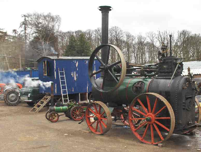
... but not this...

I chose to model the engine in 'as-new' condition (just being delivered in around 1910), and to make it in it's 'travelling' configuration, ie the chimney dismantled and laid along the boiler. The cut off chimney was replaced with a piece of brass tube with wire soldered around on end to represent the flare.


There are still a few little bits to finish before tomorrow; the wooden 'thingy' that goes around the horses' rear end (what do I know about equestrian terms
) needs to be bent down to the level of the wagon floor, and the front wheel unit can't be glued to the body until this is done. The chimney, and now I look at it, quite a few areas of the matt black..., need a second coat or touch up, but overall I'm actually quite happy with the attempt. Certainly these close-up are very cruel, but when seen from a distance (especially if the wagon and it's load are parked behind a tree!), it looks quite respectable . This is the first paint-job I've done in about 25 years and although I had trouble with the enamel paints (new tins!) not drying, and the 'slightly' older acrylics being less easy to work, I reckon with some more practice I'll get the hang of this artistic lark...Hopefully I'll have some snaps tomorrow of this wagon load being used at Newbury, and dispel the myth that wagons only carry jelly babies
-
2
-
-
As noted by 2mm Dabbler, I've used the Versaline etched chair plates on the PCB sleepers (but only the standard single chair plates); where a longer plate has been needed, I've used a piece of 0.010" brass strip cut to length. I've got some of the Versaline cosmetic chairs, but as yet I'm undecided on whether to use them or not (back to the KISS/80% solution principles)
-
1
-
-
Thanks again to everyone for the input - there is some real gems of experience coming out here and I certainly intend to shamelessly poach all the great ideas! I have to say though that I'm a fully paid up member of the KISS supporters club (I used to like their music too...) and a firm believer in the 80% solution!
But Steve, how did you get the mirrored print out of Templot?
That one was quite easy actually...
Select all items to form a group (Tabs > group > group select all templates)
Work out the mirror line - either horizontal or vertical (Tabs > group > mirror group on X at notch - (X is for vertical axis - substitute Y for vertical axis))
Then move everything back to the desired datum point ie distance from notch to origin (Tabs > group > shift group by...)
Ok it did seem easy after the event - I'm not a Templot expert, I only found this out by accident
EDIT:
I've attached a screen shot of Templot showing where the commands are that I used to create the 'mirror'...

...ignore the highlighted command, this is just where the mouse was when I took the snap shot.
-
2
-
-
Stay tuned...I am about to do 4 class 37's in one go...the lengths I will go to, to avoid making trees
See you at Expo 2020 then...build your layout at 1200mm above FFL and the jelly baby freights could see a bit of through running...Calne to Coombe
Pete
Looking forward to the work on the 4 class 37's! It would be very useful to see every detail (warts 'n all...) of each step - with lots of pictures please...
It just so happens that SWMBO has a cousin about 10 miles from Keighley, so I might even get to the Expo this year - if I can persuade her that she needs to do the family visit
I'll have to sweeten the deal with a trip to the The Keighley & Worth Valley Railway on the Sunday, but that's no hardship as I always did enjoy the (original) Railway Children (oooooooohh Jenny Agutter - must go and lie down )-
1
-
-
Yep, you can get far more blue diesels per foot in 2mm - enough to keep even you happy


2FS - Smokey Bacon
in Layout topics
Posted
Three reasons for the 'thorough' approach - 1) I'm not a 100% sure of what I'm doing so it prevents me rushing in..., 2) it gives time for people to shout out when I'm about to go drastically wrong!, and 3) it's a thinly disguised cover for procrastination
It had never crossed my mind to include any representation of the inner workings - and now that you mention it I find the thought scares me witless If all goes well, I'll include the brake work and obvious pipes on the exterior of the chassis but that is as far as I aspire to get to. The little 'daylight' that can be seen between the leading and driving wheels will be nice, and so will being able to see the (dirty) 'reddish' colouring on the inside of the frames.
For me the choice of plasticard for a mock-up was an easy one, (again stealing someone else's idea - thanks mitziblue!) I bought SWMBO a RoboCutter about a year ago and that coupled with the basic CAD packages means I can 'print' to plasticard the components as drawn - the down side is that it only scores 0.5mm plasticard as it's cut depth is 0.3mm max, but that is enough to get the outline done. The real justification was to eventually produce the frames/carcasses for the buildings on both Smokey Bacon and the Oxford groups layout, but I keep finding other uses for the toy tool.
As to the body drawings, I have several books on GWR locos (to be expected really... ) and Russell's Pictorial Record of Great Western Engines has drawings of pretty much all the required motive power. I'll have a look through the good book to see what I can find on the large prairie (I assume you mean the 61xx class?) but I don't think I've much on the BR standard classes.
Thanks for the tip on the metal. I'm still not that confident with using the mill for this sort of task and so I was intending to butcher the body with a saw and files. I suppose that this is a good time to get practising with the mill so I'll see how that this progresses.