


bertiedog
-
Posts
6,109 -
Joined
-
Last visited
-
Days Won
9
Content Type
Profiles
Forums
Blogs
Gallery
Events
Exhibition Layout Details
Store
Posts posted by bertiedog
-
-
With items from the Micron site there is no reason to go beyond using only the space for the engine under the bonnet, the back can be empty, even a Lipo battery would fit as the fuel tank,
- In O scale I would expect the vehicle to give no give away that it is radio controlled at all, virtually completely hidden......
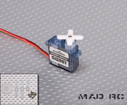
Now there's a challenge, made possible with the tiny servo from Falcon, the 1.6grm one. The tiniest may micro glitch too much for steering, but the 1.6 is pretty steady.
The Peanut scale planes I build are 12 inch wingspan scale types, fully proportional, able to take off and land under power. With the light load of a geared motor in a vehicle you would get say a half hour of use per charge or a bit more, and charging takes only a minute with electronic controlled safe chargers. The planes motors draw much more power and flights are shorter at about 5 minutes or less.
 typical small lipo batery, use in place of fuel tank.
Stephen.
-
DO NOT FORGET.....the speed controllers for planes are forward only!!!! Try robotic sites to find reversible controllers, or modifying servos to do the same task.
Basically you may get the lot, including the battery in a matchbox, with space to spare!!!!! The Falcon units are UK made by the way.........
Stephen.
-
I have used the micro caseless .8grm servo on this page, excellent for a vehicle, without changing to a coil actuator, which will not suit steering in a vehicle.
http://www.micronradiocontrol.co.uk/falcon_radio.html
They also do receivers with the servos on board, very handy. You will need to read up on the frequencies most use the new ultra high frequencies for stability. Micron will give information on legality in the UK. ...and ground based use. They are very unlikely to interfere with anything, short range and low power.
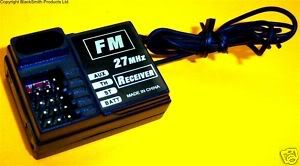
These small units are way more sophisticated than FM R/C.........
Stephen.
-
-
 1
1
-
-
This is one of the US sites, and has typical receivers......some smaller than a five pence piece.... the site has actuators and servos, and there are UK distributors of most products.
http://www.microflight.com/Online-Catalog/Receivers
The size may come as a shock, one is as small as a Futaba connector. German modellers use them in HO scale cars.....nuff said!!!
Stephen.
-
Thanks Stephen,
I had thought about driving just one wheel but I wondered whether it might sit there and spin - perhaps I better just try it...!
This was the servo I was thinking of using - nice and small at 3.7 grams
but so far I've not managed to find a receiver smaller than this - which is about 35mm long x 25mm or thereabouts...
I'm afraid you lost me a bit with the speed controller - will the board from a servo (minus the feedback potentiometer) give reverse as well?
All very useful stuff!
Thanks!
Giles
Yes the board alone with the pot removed will control a motor, speed and direction, there are articles on the net on how to do it....the small items come from Peanut flyers on RC....again on the net, I will try to source them.
-
You mentioned differentials, the best way really for smaller road models is one wheel drive, it works fine, and no slipping on tight corners.
Also have a look at the indoor flying servos, very minute items, some fit on a 10 pence piece, and are not too expensive.
The speed control can simply be a board from a micro servo, with an added driver transistor if the current drain is above about 25-100ma. The feedback potentiometer is removed and you have proportional control, not very sophisticated, but able to directly control a coreless motor perfectly as that is what it is designed for!.
You might even be able to use the coreless servo motor and gearbox, with the tab removed from the gearbox that drives the potentiometer........ a lot of robot makers follow this path, and there is lots on the net on how to modify servos to use as controllers or gearboxes.
..and for the size flat lithium batteries like phone batteries pack the most Milli ampere/ Hours figures for the volume.......
Stephen.
Stephen
-
Further to the Sieg C0 (and all other branded equivalents like Warco, Chester etc.,),the baby of the range in size, apparently it is a Unimat, as during financial changes in the Austrian maker in the late 1980's the rights to the design of the metal lathes that Emco made in Austria were sold to Sieg, who now make Unimat badged units for Europe and do the Sieg version world wide.
The early Sieg made Unimats were roughly finished, but the Austrian still control the brand and standards are now very high.
The parts are interchangeable on most items, but some Unimat specialist additions are still European made and expensive, like a thread chaser. These are not made by Sieg, but would fit, but cost as much as the lathe.
In comparison terms the Sieg is about half of what the last Austrian made Unimat cost, and must be about a third of what it would cost today if made in Europe.
The excellent Rex Tingey books on the Unimat, and others, fully apply to the C0 micro lathe in most important ways, although the Chinese have redesigned some items to improve the strength.
I had a Unimat for several years fitted with collets and it was perfect in operation. Only after buying the Lorch was it sold. I still have a fully fitted out Unimat One, and again it works perfectly, mainly as an ultra precise micro miller, and tool grinder for sharpening mills.
Stephen.
-
1
-
-
The CO model and the Smallest Sieg has not been mentioned so much it is the smallest lathe they do, and is just as capable, bar the size, which is better on the C3 , but with the price jump.
This lathe is basically the Chinese answer to the Unimat 3/4 models, everything is scaled down in size. The finish on the ones I have seen is better than the C3 perhaps influenced by the fact they are re-badged to sell as European brands, and the Germans like good appearance on the products.
Many of the Unimat fixtures fit the CO, and in fact the Unimat 4 itself is made by Sieg these days.
The chuck is a fraction limiting as it is lever closed rather than a key, and some people dislike this type, you can buy other small chucks, though at a higher price, from Arc Euro, Chester and Warco..
Stephen.
-
1
-
-
Probably been mentioned before, but this book is specifically about the Chinese manufactured lathes. Just got it this morning so haven't had a chance to read it as yet, but lots of basic how to's inside...
I have not read this book, but do not forget all the Sieg 7x10 sites as well on the web, they cover other makes as well, and general machining, there are hundreds of them. The Proxxon is about the same size and differs only in details, and many principles are the same. Sherline's books and website is useful for all mini lathe owners. Have a look at their virtual museum of micro steam engines and machine tool models.
The fact there are lots of pages on correcting Sieg "faults" is not down to bad lathes but the fact it is the most popular small lathe in the world, and more gets written about it than other lathes.
Also some of the so called faults are niggles from newcomers to power tools that would not faze anybody experienced, so you have to bone up on the in's and out's of the machine to know what you MAY have to do.
There are still a large proportion of the worlds users of lathes who complain about all machines, .....as they are left handed.....and one website on the Sieg took the Chinese to task on this, complaining very bitterly indeed, without perhaps considering all other lathes have the same so called fault!
Stephen.
-
1
-
-
On lapping a surface like a tool slide it is a process of scraping the metal flat, checking against a reference surface, and using lapping compound to finely grind the surface to a high finish, constantly checking the flatness against the reference.
However this is a bit beyond most modellers they are not going to have a selection of surface plates to check with, nor perhaps the skill to do the work, if you do know how, then by all means use the skill! Scraping and lapping skills take years to learn, it is a skill lost to modern industrial training, where surface grinding is so good now.
Minor lapping can be done to the Gib strips, in effect carefully polishing them on glass with an abrasive, then a fine diamond paste, but the easy way with the Sieg is just to scrape the steel gib strips and fit brass or bronze ones, bought in or home made, they polish easily and are smoother than steel.
The bed of the lathe should be OK, but other have posted that they have seen pit marks etc on the beds, but this does not basically matter, as long as they are small. A machined surface is an average of the top surface contact, and minor its marks and depressions do not make it less accurate, it fact they allow oil to stay on the surface a bit better.
All the Sieg beds I have seen closely where fine, induction hardened, and a ground and scraped surface.
There is no job on the lathe Sieg that requires instant attention, it all works fine, if you want more peace of mind Warco sell them inspected in the UK, and have a better tailstock lock as standard, but it's a few pounds more.
Stephen
-
1
-
-
Thanks again everyone for the information, my shopping list is getting bigger by the day.
I think I know what lathe I want (C3) and I have a good list of what tools I would like to go with it. I am now thinking about the requirements for setting up and adjusting a new lathe.
I would order the lathe from Arc Euro Tools and it would be the factory assembled version not the Arc prepared version, I would want to permorm the strip down and rebuild myself and I feel quite confident in doing this. What sort of gear would I need to do this?
I read various references to lapping so could some one explain this process and in which aspects it would apply to the C3.
Whow! ... don't jump the gun, the lathe should work from the box, stripping should not be required, you will need spirit and paraffin to clean all the protective grease off, and lots of cloths!!
The first thing is to find a table that is strong, and plug it in! but first check over for loose screws etc, and turn the chuck by hand to check it's free, then put on lowspeed and run themotor for a whil at increasing sppeed, both way, leave running at medium for a few minutes and that's it
The Gib strips can be adjusted, see manual, or ask here, and you are ready. The main bearing will be OK , you can check it though, after the running in.
Apart from the cleaning there is little to do. The main gear could be changed to metal as per ARC, but why if the original works, something to think about later.
The surfaces are hand lapped by the Chinese so leave well alone unless you are convinced the work is wrong.
But you can tidy up any scratches on the parts that are raised burrs, or decide to alter the tailstock nut lock to something better, the first job. But it works fine with the nut anyway, but the option of a cam lock with a lever is there if you want it.
Lubricate with light machine oil, or car oil, rub down paint with a mix of oil and paraffin.......and find something to make.
The only item I would say is vital is a saddle lock, they are described in all the websites and book, you will need a block of aluminium or steel and a couple of bolts to make it, an afternoons work, or a day if you paint or polish it.
any queries just ask!!!
Stephen.
-
1
-
-
For all other readers, who may rarely see a dividing head, it is a device used in machining gears and similar items with radially spaced teeth, or holes etc..
The work is located super accurately on the two centres, suspended by them, and the drive from the gearbox end locked in to zero position. A "dog" engages the work to turn it without backlash etc.
The handle is geared to the driven centre, and holed drilled plates allow sub division of each turn or part of a turn. With a normal worm drive any normal division to 1000 is quite easy. Obviously some common ones like 48 can be done direct from the plates, or sub divided or multiplied from others.
The whole thing would be set up on the bed of a vertical or horizontal milling machine or precision column drill, to suit the work to be done.
The whole idea came from watch making, where the devices date from the dawn of machinery, where clocks demand complex accurate gears in many tooth forms.
A rotary table is almost the same, but designed to take chucks and collets for single sided holding during division. It can act as a dividing head as well though, with a tailstock added, and a full set of division plates.
Most home machinists go for a rotary table with plate division, Vertex specialise in 6 inch ones that suit a lot of home workshop users. It is convertible to horizontal for dividing duties, or vertical for milling divisions like round rows of holes in steam engines covers.
Stephen.
-
1
-
-
This gives the detials of the tapers the B&S is a constant 1/2 in taper , and the No 7 is very close to a No 2 morse.

I have asked around and few collet chucks are made to fit B&S as standard, Bridgeport did them, and Schaublin list them, but you are talking a lot of money.
Now do not take this the wrong way, but why do you need to mount a collet chuck on a dividing head, when most work on dividing heads is held between centres? I know it depends on the work, and all the alternatives, but usually a collet chuck would be added to a rotary table with dividing drive where it is impossible to mount between centres. This is why so many Rotary dividing tables have common morse or R3 taper mounts.
A dividing head like the B&S may be able to sub divide further, to about 1000, than a simple rotary table, but the Vertex can divide to 1000 or more with the same precision, a morse centre is popped in and it acts as a dividing head. I have 10 sets of plates to do any common division to 2000, some custom to save counting the jumps!!! My own tailstock for the vertex is home made, cast for me in iron, and machined to look like the B&S type.
Stephen.
-
Now that looks to be the machine tool. B&S O. The beast way would be to get a new collet holder to fit the M/C not to make the M/C fit the collet holder. As I said I could M/C the holder but I can use it in the lathe.
So it it is now down to where to get one to suit the dividing head?????????????
OzzyO.
The problem is B&S do not make them any more and current Chinese made Vertex clones are fitted with Morse, so the call for adaptors is very small. If it is the model O B&S then there is another problem, the two tapers are very close and a sleeve would be a bit impractical, it might work, but it would need a bit of trial and error. It appears the B&S is shallower than morse and the sleeve would make the centre stick out a long way.
It may be the collet holder has an inserted tang, which might be removable, and you could interchange the tangs as needed. The only other way is to source anothe collet body already on a B&S taper, and that is going to be difficult now that the head use Morse so much.
Stephen
-
See Ebay for Morse No one machinable morse arbors if you make a tiny ball raced centre.........
Plenty of other suppliers exist, but make sure the end is machinable, in a soft state, the listing is for UK made Picador type not made any more, but he has a few in stock.
No1 Morse is a popular size for smaller lathes, but bigger may take two or three in the tailstck. Myford use No2, and No3 on bigger versions. The Seig has a No2 morse, the Proxxon No1.
An exception to all of this is Unimat 1/2/3..... and they have no taper in the tailstock, but a parallel plug fit, very easy to adapt the tiny live centre design to.
-
Ozzyo, ........further to the query on the dividing head, it sounds as if it is a Brown and Sharp,(B&S), and if like the standard B&S units it is fitted with a B&S taper number 7 or 8 for B&S number 0 and 1 and number 10 for the B&S model 2
This would have to come from B&S or a outside supplier, and by the look of the combination a Morse conversion may not be practical, the tapers are very close. It looks like the collet set will need a new number 10 taper tang to fit. I may be able to provide the taper details for the number 10, but I cannot in any way g/tee what is actually fitted.

However there is another approach, and that is to strip the entire rotary dividing head, the core with the number 7 or whatever version the model has, it could be re-machined or bored out and a sleeve inserted, but this is a task for a machine shop with decent boring and grinding to maintain the B&S accuracy, which is extremely high.
http://www.hexagonmetrology.co.uk/ are the name B&S trade under these days and might be able to help.
Stephen.
-
Hello all,
as we seem to be getting a bit bogged down with some of the more advanced things on machining, let us try to go back to what I set this thread up for (I'm to blame as much as the next man) advice.
A few year back I bought a dividing head for my mill, I then bought a full set of ER25 collates with a No.2 Morse tapper collet holder. Now you have guest it the No. 2 M/T dont fit the dividing head. The dividing head taper is B&O (O&B?). Close but no cigar.
Now does any one know where I can buy a collet holder with the B&O (O&B ) taper (I can use the No.2 Morse tapered one on my lathe). Or is it going to be a lot of taper turning for me. That's if its not been hardened of course.
As a last resort I could fit the dividing head with a 3 jaw chuck but run out and the extra length from the M/C head dont help.
OzzyO.
What's the model of the rotary table/dividing head? (O&B?)if it is a standard taper in there, usually they are short form morse, but others are used, I have full lists in Machinery handbooks which may identify, but you may have to turn a sleeve as the tapers are different, and not many makers do converters from one taper to another from stock, unless a popular conversion from MT types.
Most dividing heads come with an un-machined blank to fit the taper, and maybe the original supplier can help with the blank. The smaller Vertex rotary table has a number 3 morse, but the Schaublin dividing head with plates uses a Brown and Sharp.
The angle can be measured by the diameter at the base and throat, measure the distance apart and trig provides the angle to identify it.

I assume this is the type, I have similar, and the taper in these is morse on most, as it is used mainly for between centre work. The morse is often a half length morse and a full tang will not fit some times giving the impression that the taper is different.
I assume you may know this already, and the comments are for all readers as well.
Stephen.
-
An oft quoted objection to these methods is "I don't have a live ball raced centre" or the centre I have is awkward and too big, so lets make one in the lathe, it should take about two hours at most, given scrap materials to hand.

First you need a blank morse taper, in soft steel for turning, if you have a hard one then heat as hot as possible in a propane flame ad then cool slowly, it will now be soft enough to turn. The size morse should match the tailstock of the lathe
Take the chuck of the lathe off and fit the morse into the headstock, most headstock tapers are bigger than the tailstock and a sleeve can be used to convert, they are easily sourced and useful items to have, (It allows the tailstock drill chuck to be mounted in the headstock). Some small lathes already have the tailstock and headstock the same size, like Toyo, Proxxon, and Unimat, but it varies with model.
Find two ball races that can take side thrust, or at least one that can, of a suitable size, say 6/8mm bore, and a case of say 10/15mm, it is not important, any diameters can be used in proportion to the final small size. Two ordinary ball races will work, after all, the side pressure for this use, is relatively light.
The morse shank blank end is then turned down to leave a stub that can take the bearings, a nice push fit, not too tight, and loctite them onto the shaft as in the drawing.
The lot is removed from the headstock and the three jaw returned to position.
Find a scrap large steel bolt or a piece of steel about 3/4 inch, in proportion to the outer diameter of the ball races, and turn to shape the whole out sleeve, the hole will have to be bored to size, and then turn the work around and turn the cone end. This should really be done in a four jaw, but a good condition 3 jaw will do.
The sleeve is then slipped over the bearing and tested that the centre runs true as the body turns, if you have used a three jaw to turn the point you might have to try again if it has a wobble on the point, but as long as it seems true to within a thou or less it will work. If the sleeve is set with a dial gauge in the 4 jaw it should be true full stop!!
After testing pull the sleeve off the races and then loctite them back one, and that's it, you have a custom tiny ball raced centre.
You can make this type as tiny as you want, you are saving many pounds making one, and they don't sell them this small unless very expensive clockmaker's types.
For day to day work a normal larger live centre can be bought cheaply these days, the FE ones are quite accurate, but, with say a Sherline, it needs the very smallest size to not get in the way of the smaller workpieces.
Stephen.
-
1
-
-
Stephen, I'm really interested in how to true up wheels such as Romfords/Markits on the axles and suspect some of the pics in your last posting might help me understand how it's done. Only problem is that I can't see any pics. Have you left them out or have the picture files not loaded?
The best way with Romfords is to copy the basis of the Gibson type,(drawings posted), with a recess in the mandrel face, and the washer, to grip the rim edge. The centre of the mandrel can be drilled with a centre drill, and then drilled and reamed 1/8 inch and an axle inserted and epoxied into place, with the square end far enough out to enter the back of the wheel, the screwed part is then turned off.
The wheel just slips on to the square and the disk pressed home with the ball raced centre. The mandrel should be mounted in a collet or in a marked three jaw to be able to set it up without to much hassle, but it could also be set in a four jaw.
The raised edges should be sized to touch the outer rim of the wheel to grip the nickel silver tyre, not the mazak centre.
Stephen.
-
Hi Stephen,
Ermm,I think a mandrill is an Ape with a very colourful backside,I think it`s a mandrel

Ray.
Written both ways in Machine handbooks, but I will correct it for you......
-
Working with any small lathe and wheels in smaller scales up to about gauge one.
The methods are well known, but act as introduction to newcomers as well to lathe uses.
One of the main jobs that a small lathe is used for is producing wheels or modifying the existing wheel, taking a commercial product that can be made to conform to a tighter standard etc., or replacement of tyres on mazak cast wheels with a more suitable tyre.
You can also mass produce wagon and coach wheels from scratch, maybe for P4 or less used standards like S scale.
Any of the small lathes from the Sherline upwards can handle these jobs, it needs a bit of planning on holding the wheels for machining, mostly out of the chuck on a mandrel or spur point.
The most common request is reduction of the flange, taking a Lima wheel as an example, the flange is about twice as high as it could be reduced to. Most of the older Lima wheels were brass, chrome plated, but it will work with the mazak chromed as well.
The wheel, removed from its axle is not able to be simply gripped and the flange removed, so the first job is to chuck a bar of steel, say 3/8th inch(8/9mm metric in the three jaw, and turn a matching end on it to fit the Lima axle size,(or other). As the mandrel will be used many times it is worth reverse chucking first and putting a flange that will consistently rest against the chuck every time the mandrill is used.
The stub for the axle should stick through about half way, and have the end drilled with a centre drill to allow space for the point of the ball raced centre to fit without touching the stub when the wheel is fitted.
The mandrel should be marked to match jaw number one to allow return to and accurate position for each use, and the concentricity should be checked before use. Most three jaws are accurate enough, but if you want on larger wheels the mandrill could be set in a four jaw chuck for complete accuracy.
The mandrel is readied and the wheel slipped on to it, now comes the hard part, getting it to be turned by the lathe, and the easiest way is a live centre fitted in the tailstock, and to simply press the wheel onto the mandrel back, with sufficient pressure to hold. The centre revolves with the work, and the wheel is very accurately held. All small lathes come with, have available, or it's an accessory from any independent supplier, a ball raced live centre, (or you can make your own in the lathe should you wish.)

The flange can then be reduced and the shape of the tip filed or turned and finished with abrasive papers.
When abrasives are used , cover the slideways with paper, or cloth, and remove any dust made. Only use a file if you are experienced in such work, it is classed as somewhat dangerous, but is an accepted Jewellers and clockmaker's method.

The whole wheel can have the tyre removed till it is flangeless, or reduced further to take a new tyre, on for example a mazak chrome finished wheel, which lots of modern ones are.
A non insulated wheel is easy it presses against the mandrill, but an insulted one should have a washer added at the back to allow the pressure to bear on the metal parts.
Some Bachmann wheels have only a cast back, and some have raised surfaces and pips, so prior to re turning they would go in the three jaw, or a collet to have the back trued up first.
All of this covers metal centred wheels, including Romfords, which can be turned on one of their own axles if needs be.
With plastic wheels and scale wheels being returned, like Gibson, then a large mandrel face is made to match the diameter of the wheel so that the force is taken by the steel tyre, and the live centre bears on a washer made with a rim to press on the tyre, this removes all risk to the plastic, which on a spoked wheel cannot take the forces of turning.

All so far is accurate flange reduction or removal, the new tyre would have to be turned and a profiled tyre shape turned to continue the process. None of the above should be beyond any small lathe, or a newcomer to turning.
You can use such mandrels to hold blank wheels of your own for mass production, but usually a form tool and parting off a finished wheel is done from stock bar material, to be described later.
Next part, making a profile tool or using a commercial profile for re-turning or tyre replacement.
-
1
-
-
NO, the correct/normal/every day/usual/ accepted way is the front and right way up, the others are alternatives and only shown to show what they do...it is horses for courses. If it is a Colchester 20 inch lathe it ain't going to notice anybody messing up parting off, but if you do it wrong on a Sherline it is going to protest in no uncertain terms!!!!!
The Myford is an exception in some ways, it is a very fine lathe, but parting off can be troublesome to people who only have half the story, it needs to be well adjusted to part off well.
This is very well documented, it has been addressed by Myfords with redesigns within the design of the lathes bed,...... the final word is parting off is OK on a good condition machine with a good operator, too often I see a badly adjusted Myford with a newcomer to lathes, and Yes, I have seen half a broken parting off tool buried in the ceiling!!! it juddered, dug in, and before he could operate the clutch the tool shattered, but it was that operator, and it might have happened on any small lathe.
I was trained in engineering with Post Office Telephones(BT), STC, and Cable and Wireless, and worked later in model engineering and model manufacture, and then in optical instrument making and making lenses and scientific instrument making....and I started on lathes with my father at the age of six, on a Drummond round bed I still have, and that's fifty four years ago.
Stephen.
Stephen.
-
One other point I had in mind to mention on parting off and it involves insert tips as well, it that upside down tools clear the chips of swarf better than the right way up, .......it's gravity you know!!,... and also for parting off the geometry of the carbide insert tips breaks up the swarf finer than the conventional HSS blade grind, again combined with up side down there is liiitle chance of the swarf causing drag and inducing judder or jams.
George Thomas, who designed his famous rear tool post holder for the Myford,* said a top rake of 7 seven degrees was best for general work with steel, both front mounted or rear mounted. This ties in with Sanvik inserts.
The other vital point I did not mention is that the blade must be at right angles to the work, plus or minus nothing!!! Check both sides with a good miniature try square against the turned work, or a test bar in the chuck, a fraction of a degree either way, and friction builds up and the tool tip is deflected.
The carbide insert parting tools are kinder in this respect, they are are only a small side length, then a thinner holder, so out of right angles does not how too much, but it still counts on finish and safety, so still check with the square.
Stephen.
* George Thomas's books and ME articles cover the design of the Myford saddle and its limits etc., in great detail. He was a deeply respected author and expert tool designer. I use one of his toolposts in the Warco lathe, expanded to the bigger size from the Myford series 7 type.
-
1
-


Radio Controlled locos, lorries, cranes etc. Electroplating
in 7mm+ modelling
Posted
On the Portescap motor it would not draw 500ma, as you will not be using full 12 volts, the radios use 6 volts of so, (2x Lipo batts), and most coreless motors draw only about 25/50 ma to run, and the load is light on the Portescap.
An alternative is the tiny motors and gearboxes used in camera lenses for autofocus, a supplier here:
https://secure.precisionmicrodrives.com/
or rivals on Ebay. They are small enough to go across the lorry, and have a belt drive, (Nigel Lawton) to the axle .....they are not coreless, but are low voltage and drain, and quite inexpensive, have a look at the smaller versions. If you get small plastic 1:1 bevel gears it could be mounted in line under the floor.Most are very high geared, 150:1 perfect for vehicles low speed range.
..........to finance the radio and motor, you then auction the Portescap on Ebay!!!!
I will try to find relevant articles on servo conversion to speed controllers.