
009 Sandy Shores - My first proper go at painting/detailing a locomotive!
Entry posted by SouthernRegionSteam in Rolling Stock
412 views
It's been a while since I've posted. To be fair, I mainly post my narrow gauge projects on my external blog (https://jamsmodelrailways.blogspot.com/) and on NGRM-online. However, I thought that this particular update would be worthy of a blog entry; as it describes the full process from start to finish, using 33 photos along the way... so let's begin!
Before the madness of the festive season drew to a close, there was something I wanted to finish off whilst I still had some time to do projects for myself! I recently bought a secondhand Minitrains NS2F to finally boost the number of decent locomotives on Sandy Shores from two to three! (OK, so technically I also have the Bachmann Dorothea, but I'm not overly enamoured by it's running qualities I must say). This NS2F was bought from the 009 Society's Secondhand Shop (well worth becoming a member by the way, if you haven't already!). Here's how it arrived:

Above: Clearly, the orange has to go - it, and the red underframe, are incredibly vibrant! You may remember from previous posts that I did want the blue version, but truth be told it wouldn't have made a slight bit of difference as it would still likely need to be repainted. In any case, the chassis also needs more work, but more on that later. First things first, we need to try to remove the body.. but how?
A quick note before I continue - you'll have to excuse the differences in colour temperature of the orange of the loco body. I forgot to remove the custom white balance after having photographed the layout on Christmas Day for a future article! Some of the following photos make it look more yellow, which is incorrect. Anyway, back to the practical...

Above: ...well, fortunately, I found one photo online that showed the body removed. It was clear from the visible paint damage to the underside of the body and the top of the chassis in that photo that it is simply glued in place, with locating pips front and back. It was also obvious that the solebar is connected to the body as one piece. Something to bear in mind here is that trying to do anything to a locomotive terrifies me (hence my never-fixed Lilliput shunter that broke years ago)! Yet still, I hesistantly took a knife above the buffer plate, and started to twist and rock it to try and get the glue to part. Thankfully, with only minor dents from the blade, it came off cleanly after a nerve-racking 'crack' of the dried glue separating! Pulling the body off, we can see that the bonnet is entirely filled with a metal weight, with two tiny wires leading to a micro LED at the front.

Above: One long screw at the front of the loco looked like it held the weight in place, so this was unscrewed. However, the weight still held tight. I therefore removed the plastic spacer by undoing the two screws, which revealed a fourth screw. After removing that, the weight did jiggle quite a bit, but I wasn't sure if it was attached in some other way. I guessed that the two longer screws probably had held the weight to the body without need for additional fastenings, and that the resistance was probably down to the weight scraping against the bodysides; so I grabbed my fine-nosed pliers and gently pulled the metal weight out - phew - it slid out easily! Note how, in the bottom right image, the area of the bonnet around the front headlight has been painted black on the inside - I'm guessing to minimise light leakage/the possibility of the bonnet glowing! I've got to say, it's a well constructed model, especially with the channels in the weight to hold the LED circuit board and the tiny wires. All very tidy, and everything slots together easily, much to my relief.

Above: I noticed in various photos online that there was quite often an obvious gap under just the cab section. Pulling on it, I could wiggle it a little, so it must indeed be able to be removed - which would be handy, as I'd love to fit some 'glass' to the windows, and it would also make painting it easier! One side unclipped easily, but the other wouldn't. As it slides on two parts of the other half of the body, I realised I could wedge a flat jeweller's screwdriver through the window, and slightly pry the cabside out a bit. That had just enough 'give' to be able to release the clips, and it slid right off.
The second photo shows that there was some sort of 'works' plate on the back. I know nothing about transfers (assuming that's what it even was!), but I could feel it was slightly raised, so opted to gently remove it with a fine needle file. In hindsight, and after having read more online, I probably should've used some IPA on a cotton bud, but too late now!

Above: I figured, knowing nothing about repainting, that it's probably wise to give the factory finished paint a new coat of primer before anything else. But I needed to find a way to support the two body parts whilst spraying them. Looks like I've suddenly found a use for old sprues - though I don't think I'll ever use many from the box that is full of them! Anyway, note the weird effect on the roof - stupidly, in order to spray from the underside, I rested it on a foam block, which of course reacted with the spray paint... whoops! I guess I should've Blu-tac'ed the support to the roof first, sprayed the interior from the bottom, and then sprayed the rest - with the support in the position visible in the photo. At least, that way, any missing paint from the ceiling won't be too visible if it peels off when removing the Blu-tac.

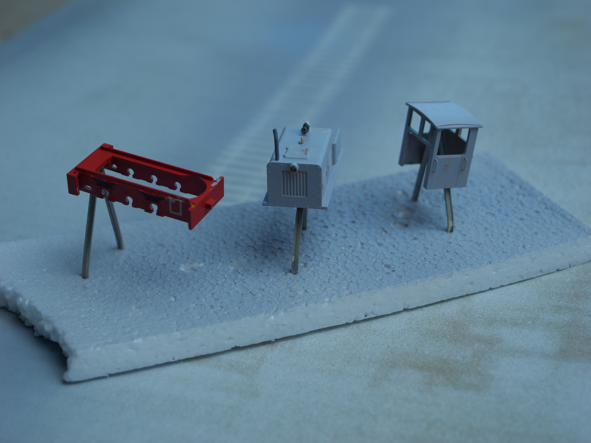
Above: Here we see the set-up for the third spray layer. You can actually see the channel on the right hand larger body piece that the cab slides into - just to the right of the furthest louvred door. The little stick on the far right is the exhaust - which appears to have been possibly just a friction fit into the corresponding hole on the bonnet.
And now I have to fess up! The roof debacle wasn't my only mistake. I made another amateur error... instead of the cardboard I usually use for spray painting on, I first, mistakenly, used the large one that has static grass over it (from making trees and applying grass to small dioramas). The result was that the spray cause a few static fibres to attach themselves to the body... whoops! Whilst I removed what I could with my fingernail, I didn't want to risk using abrasives all over the body. The end result is that the bonnet has quite a few bits of static grass over it, but I'm hoping I can disguise it with weathering - perhaps I can get it look like peeling paint somehow... anyway, let's move on... to some more mistakes(!)

Above: I mentioned at the start about wanting to do more work to the underframe. Having looked at prototype photos of the NS2F, aside from the overly thick metalwork, which would realistically require an entirely new frame and body, the other big thing that stands out to me as being 'wrong' are the chunky cab steps. On the prototype, these have really thin metal vertical supports, much like those on my brake van build. However, as shown in the photo, the step and supports on the model are incredibly thick, and fully moulded as part of the chassis frame.
At this point, I wasn't going to even attempt to remove the steps as, although it was easy to slide the chassis out of the frame as there are slots for the axles to slip through, the metal weight would not fit through the frame. As it was connected by the thinnest wires I've ever seen, (that take power from the pickups to the LED headlight) I didn't want to unsolder them as I feared I'd never be able to resolder them later.
However, when my usual lack of confidence reared its head, fate had other plans; as I accidentally fumbled the weight, which hit the cutting mat, and in turn, pulled one of the wires from the chassis. ! Well, I guess it was meant to be... so I thought I might as well give it a go:

Above: Though, as you might just be able to see in the photo bottom middle, I didn't yet dare to unsolder the second wire (I'm not sure why looking back, as I would've had to resolder one wire on anyway, and it would've made this next bit easier!). Anyway, a quick trial of cutting away the steps with a knife proved that it would be a slow process - as the plastic is thick and fairly hard. Therefore, I opted to use a conical sanding attachment on my Dremel. A potentially risky choice, especially as it could easily wander and damage either the buffer beam, or suspension/axle box detailing. However, being cautious paid off, and no damage was caused. The brown paper top right is covering the chassis to prevent any fine bits of plastic getting lodged in the mechanism. Anyway, after the Dremel, the rest was taken off with careful filing with a flat needle file. Just like the conical sanding disk, it was crucial to go slow, and check the progress regularly to ensure I wouldn't end up going too far.

Above: Don't laugh (OK, you can!) but after the steps had been successfully removed, I opted to finally unsolder the second cable. Whilst doing that, I happened to notice that one of the cables from the pick-up on one side to the motor was barely hanging on! Perhaps this was part of the reason for the locos apparent random stalling? (The inset photo, top, shows this dodgy connection). As can be seen by the bottom inset photo, I did attempt to resolder, though looking at it again, I don't think I really achieved much, as I still see frayed wires. It was difficult trying to get a soldering iron in there (especially the god-awful ruined tip of my one!), which is evident by the melted plastic pip that holds the pick-up in place, along with the melted insulation on the wire. Quite how you remove insulation on wire this tiny that's already in place, without causing damage to everything, I've no idea!

Above: Another, more minor feature that differed on the model from the prototype was that there were holes on the front and middle of the chassis. No idea, other than possibly lifting points, as to what these are, but I felt I could perhaps attempt to model them now that the chassis frame was separated. Thhis montage shows the steps taken; first, two holes are drilled, which are then connected with a knife, and then filed to shape.

Above: Before we move back to the body (we'll sort the steps out later, as they would need to be fitted to the bottom of the soleplate, and would be too prone to damage until everything is put back together properly), a further look at prototype photos showed there to be an additional mechanism on one side of the chassis frame. I worked out that this is likely to be the brake mechanism, as there appears to be a handwheel visible in that corner of the cab on the prototype. Wondering how I would model it, I suddenly remembered the first version of the handbrake handle that I built for my guards van. It's an astonishingly close match! All that needed to be done was to trim off the shorter section to the right of the 'ball', and to flatten the top of the 'ball' a bit with a file. Once glued to the chassis (note the outline of the step which would've otherwise been in the way), a small rod was glued to represent the brake spindle.

Above: There were quite a few moulded handrails on the body, which would naturally look more realistic if they were replaced by bits of fine wire. However, those on the louvre doors on the sides would, I figured, be too prone to being damaged when handling the model. The access hatch on top could be a safer option - as it will be amongst other raised detailing later on. Therefore, a piece of incredibly thin microstrip was bent around the end of my fine-nosed pliers to form a U shape. The handrail moulding could then be careful cut away with a knife, and then the new handrail glued into place. A relatively quick modification, but one that makes a big difference. This isn't shown, but later on, the circular object on the bonnet also had a handle fitted - as per the prototype. What this is, I've no idea - my only guess is that it might be the fuel filling point?

Above: A few other additions were made using the same tiny microstrip. First, door handles, and secondly, rain strips. The latter have been done in the 'traditional' style with a curved piece on the edge of the roof that directs rainwater to the edges of the cab. However, on the prototype, it seems that a thin metal sheet was used over the whole roof, with the two ends above the doors curled up. I realised this too late, and besides, the roof is already well-over thickness without adding another layer on top!

Above: Having not followed the prototype as far as the roof strip was concerned, I took yet another look at the prototype photo to see what else might differ. I suddenly realised that all of the images I could find had the exhaust on the front right of the bonnet, not the rear left (closest edge to the cab). A suitably sized hole was therefore drilled in the correct position, and the old hole filled in with Humbrol Model Filler (applied with a jeweller's screwdriver), and then filed once hardened.

Above: I didn't like how boring the current exhaust pipe was, either. I considered adding one of those 'flaps' on top, but felt it wouldn't look realistic fixed in the closed (or open) position when in motion. Inspired by a couple of prototypes, I took to bending the last few millimetres. However, the original plastic one was too brittle, so it was remade in the same diameter plastic rod. Note that the end has been very slightly drilled (though I stopped once it started splitting!) to give the impression of a hollow pipe, and that the end has been cut at an angle.

Above: When I first started in 009, I planned to make a classic Knightwing Diesel Shunter kitbash. Whilst this did get put together to some degree, in the end I took it all apart with the intention to rebuild it into a new configuration. This clearly never happened, and it has been languishing in many pieces in my spares drawer! I really wanted to add something else onto the bonnet or cab to further detail it, and I realised the old horn from the Knightwing kit would be perfect. Looking at photos online, either it would likely be mounted on the roof, on the front of the cab, or on the bonnet. I chose the latter as it would be less prone to damage, and there was more space. A simple bracket was therefore made from 20 thou (I think) plasticard - two 'gable' shapes for the main bracket, with a triangular support for strengthening the back. Once assembled, it was simply glued in the centre of the bonnet, at the back, where it would be out of the way.

Above: Other than the repaint, there's one more thing that I'd like to add, again, inspired by a couple of prototype photos. As mentioned, all metalwork, especially the cab, is far too thick. I noticed that some locomotives gained new windows in frames mounted to the outside of the cab. This, I felt, would not only create a more interesting and unique model, but it would hopefully mitigate the effect of the super thick plastic walls to some degree. Here's the basic materials for the start of both window frames; 20 thou x 40 thou strips, with four long pieces for the top and bottom frame members, and 8 vertical members. As you can see, these are glued together, with help from a needle file to delicately align them correctly. The paper underneath prevents the plastic cement stick everything to the cutting mat.

Above: I knew that I wouldn't be able to accurately cut out 'glass' (i.e. clear plastic packaging) to fit within each aperture perfectly, so I came up with the idea of using thinner microstrip pieces to make a raised frame, which slightly overlaps the inside of the aperture of each window. Thus this acts similarly to beading that's used to secure glass into real wooden window frames - allowing the 'glass' to be dropped in behind, and glued in place. Whilst this was a little bit fiddly, with care, it was actually surprisingly easy to make!

Above: As I needed to fit the 'glass' before glueing the frames onto the cab, I opted to first paint the frames. For this, Vallejo Model Color 'Azure' was used - the colour I intend to paint the locomotive later on. After two coats, the 'glass' was cut, trimmed, and placed against the beading from behind. A little bit of Deluxe Materials 'Plastic Magic' was used to glue them in place.
Above: And now for the bit I wasn't looking to doing - the painting! First, another coat of primer for the body, now that additional detailing had been added. Note that I'm using old bits of rail, which the parts are Blu Tac'd onto - these A-shaped rail structures were going to be pipeline supports for my Fawley Oil Refinery layout! Anyway, as the chassis frame steps have been removed, the chassis was now ready to be primed, too.

Above: The chassis frame was tackled first - painting it a slightly(!) less vibrant red than before. Even if the steps hadn't have been removed, the fact that the repaint is almost an identical colour doesn't mean it would not be worth doing anyway; the weathering powders that I will be using later will require a matt finish to be effective, so I might as well paint over the shiny factory finish. I accidentally mixed too much paint, so that's partly why the two bolster wagon kits that I'm building also got painted with it.

Above: Everything gained 3 or 4 layers of acrylic paint - each was very slightly watered down, and painted in alternate directions to try to minimise brush strokes from being apparent. With my painting skills, it will never be as good as spray painting, but I'm not investing in an airbrush any time soon just for occasional projects. And to be quite honest, I'm happy with the final results that I've achieved. Anyway, here's the body being painted, the leftmost photo showing the first coat being applied, and the rightmost showing the second going on top. The difference between 1st and 2nd coat is quite surprising!

Above: After the blue was done, I started painting all the other bits. To be fair, not many colours are needed - just greys for the roof, handles, grille, and lower interior of the cab, white for the upper interior of the cab, and finally brown for the inside edges of the door/window frames. I've definitely got better at painting carefully and precisely, but there were still a couple of spots of blue that needed touching up.

Above: With all the painting done, it was time to add the windows. Now, I could've, and should've, filed away the slight raised frames of the original. However, as I'd already painted, and I felt it might be hard keeping the file consistent across the whole width, I opted instead simply to glue directly on top of the raised frame detail. To be fair, whilst there is a slight gap, it could easily be covered by either adding more plastic cement, more paint, or filler. Oh, and the photo on the right is to do a dry-run, and check that the paint wasn't stopping the parts fitting together. And I guess also because I wanted to see how it was looking overall!

Above: Originally, when it came to weathering, I was going to paint 'rust' everywhere, however, I was reaching the point where I just wanted to get the loco finished as I'd spent a LOT of time on it! Thus I took the simplistic approach of using weathering powders to create a more 'generic' grubby look. I say generic because although I've tried to copy the prototype as far as grim is concerned, I'm not applying it with a critical eye and going into great detail. As the photos try to show, all I've done is add dark grey for generic grime and oily areas, a dark brown to represent brake dust around the bottom of the frame, and light brown for rusty patches. The latter is incredibly simplistic, but particularly on the buffer beams I think it actually works better than I thought it would!

Above: Here's another look at a different part of the loco being weathered - the front end. First the generic grime around the bottom and edges (and grille), then muddy grime along the bottom, and finally rust applied to the bolt heads and down around the front light casing/grille.

Above: Here's a before and after. Sorry for the lack of depth of field in the second shot! I think the transformation is pretty clear to see though. Suddenly it's changed from a toy, to a model. At least, I think so anyway! Eventually I'll probably spray matt varnish on it to protect it from handling, but for now it's too cold for that. P.S. Note the rust streak that runs from the exhaust stack, then down the side of the bonnet - same for the various handles.

Above: We're nearly at the end, but there's a couple more items to add - first, the curtains to hide the very obvious motor in the cab (something I should really do to the two other Minitrains locos as well)! Once again, I found that some prototypes were retrofitted with curtains, so I knew roughly what I should be aiming for. To keep things simple, rather than model partially opened curtains which would require folding, I just created flatish ones from tissue paper, and modelled them fully closed.

Above: And finally, the cab steps! Now, I have to be upfront here as I've made them mude wider and thicker than the prototypes'. However, judging by the wonky state of many of them, I feel like it wouldn't be beyond the realms of probability for them to be replaced at some point. Besides, the width of the prototype ones was ridiculously narrow, in my view! In any case, they were made, as you can see, using two sizes of styrene lengths, in 4 pieces. Two uprights of 0.020", one step plate of 0.010", and a further 0.020" bottom. I won't bother to explain the assembly as I think it's clear enough in the photos!
I must admit, I haven't yet soldered the wires to the LED light back on. Purely because I wanted to get some new photos of the layout for the 009 Society article with the diesel in - so I was in a rush to get it 'completed'. That also means that the loco, currently, does not have the weight in it - so it's pretty back-heavy! Hopefully the resoldering will be relatively straightforward, but if it's not, I'll come back and add more to this post...
...in the meantime, to summarise, this certainly was not a quick project! However, being my first successful loco project, it has given me some much needed confidence. Perhaps enough now to tackle the replacement motor in my Liliput shunter that died many, many years ago - that will require part of the weight to be removed to fit the new, slightly bigger motor in, as well as working out a way to secure the motor in place. Anyway... that's definitely a project for a future post!
To finish, let's look at some photos of the finish model, starting with a comparison between the original form, and the final form:

Above: It's amazing what a difference a repaint, some detailing, and a tiny bit of weathering can do! Though to be fair it's taken a week of work, so it has been something of a labour of love. I suppose the only things that stand out now as wrong are the unpainted counterweights and coupling rods. But I'd prefer to leave mechanical bits as they are, where possible!

Above: A view showing the rear of the NS2F, as it slowly rolls backwards to couple up to the tank wagon (though I've just realised the wagon is facing the wrong direction and there is no coupling hoop on the far side!).

Above: The loco patiently waits on the loco shed headshunt. Either the driver has gone for a walk to the kiosk by the harbour, or he is napping in the cab somewhere!

Above: A final look of the completed engine as it waits for its driver to change the point that leads to the sidings so that it can resume shunting. In tow, the commemoratively liveried goods van, with the 009 Society's 50th Anniversary logo on the side, clearly needs a good clean. Judging by the similar state of the loco, I don't think that will be a top priority for the crew! Personally, I think the loco is a perfect fit for this tatty sunbleached seaside railway. But what do you think?
I hope that you've found this blog post informative or perhaps even inspirational! I'd love to hear your thoughts and suggestions on anything featured here.
Many thanks, and happy modelling,
Jamie
-
 17
17
-
 1
1
-
 1
1


3 Comments
Recommended Comments
Create an account or sign in to comment
You need to be a member in order to leave a comment
Create an account
Sign up for a new account in our community. It's easy!
Register a new accountSign in
Already have an account? Sign in here.
Sign In Now