Jump to content
 

GWR Park Royal stable block


Mikkel

4,412 views

38337773296_970c354e8d_o.jpg
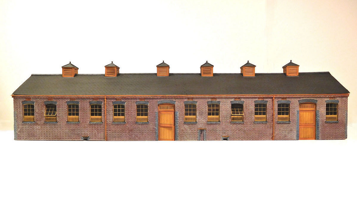
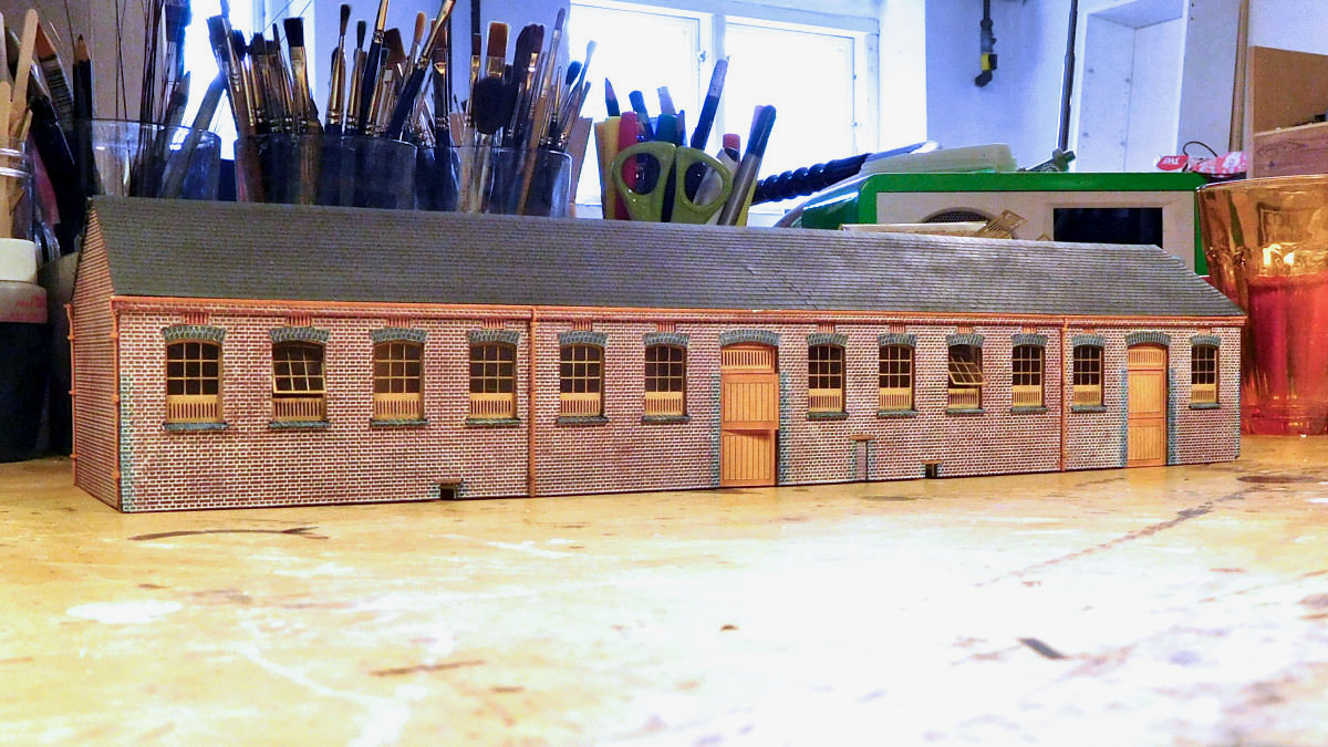
My model of the GWR stable block at Park Royal is now almost done. Here's an overview of the build and some pics of the finished item.


38345472596_550272e31d_o.jpg


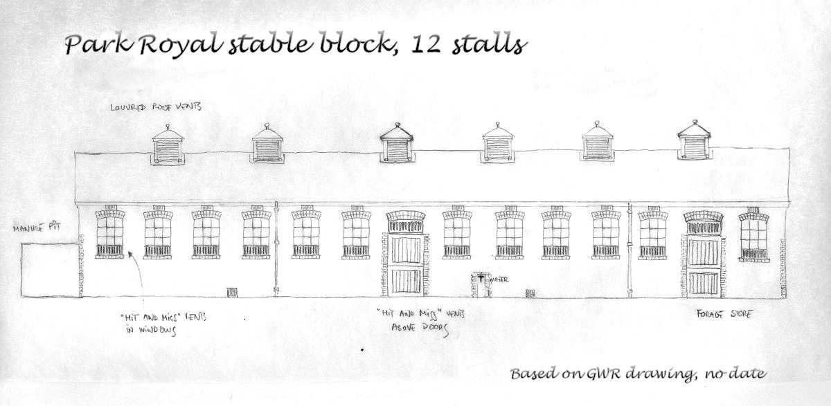
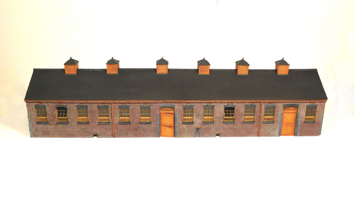
The stables at Park Royal followed the classic outlines of what I call the “Style B” of GWR stable blocks. Above is a sketch. The model itself was built using the GWR drawing that is reproduced in "Great Western Horsepower" by Janet Russell and in Adrian Vaughan's "Pictorial Record of Great Western Architecture".


33351834026_07eccefb7e_o.jpg


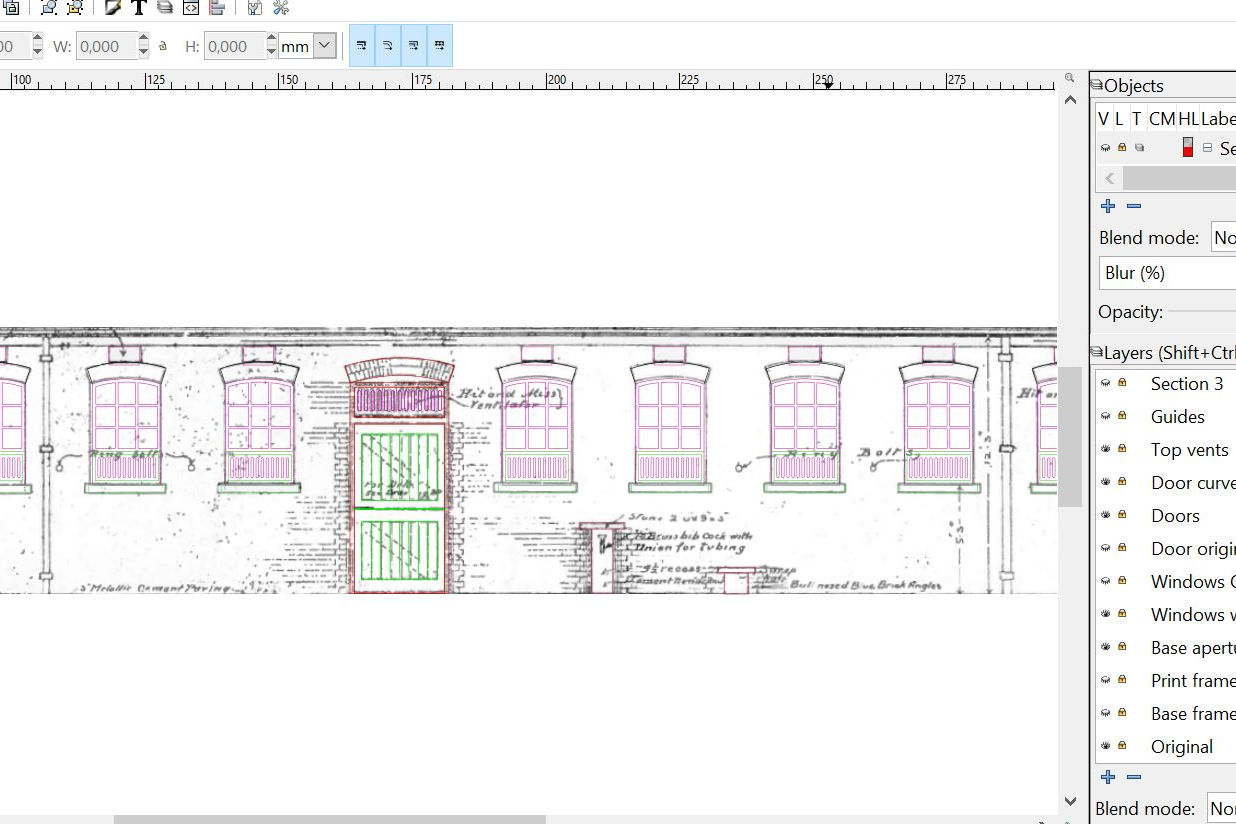
I used my Silhouette cutter extensively for the build. The GWR drawings were imported into Inkscape, on top of which I then drew up my own drawings for the cutting file. Getting the hang of this was a learning process in itself, and I’m grateful to Jason and Mike for their excellent threads on using the Silhouette and Inkscape.


34952667102_0b0af28765_o.jpg


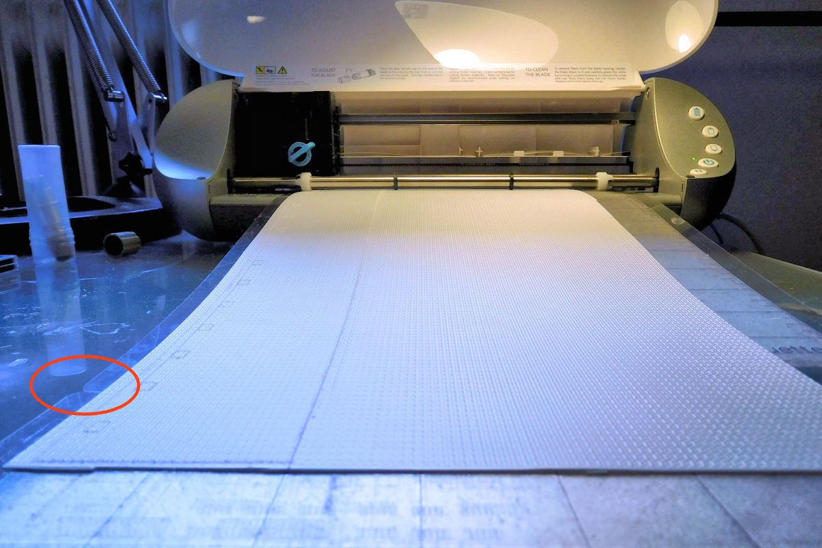
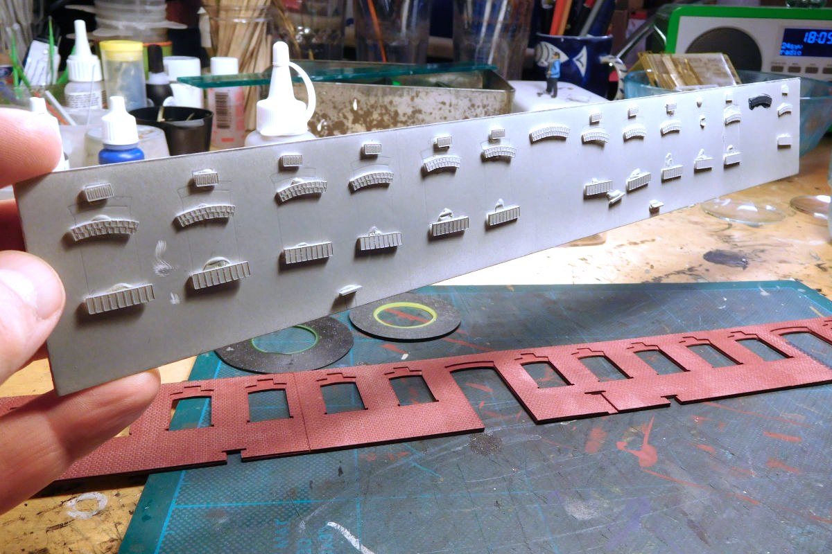
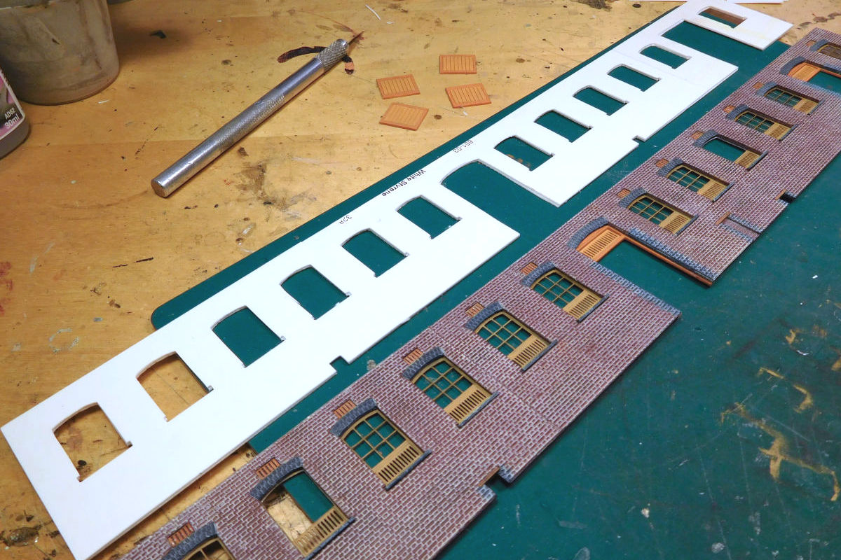
The digital drawings were used to print the main sections on my Silhouette Portrait cutter. The cutting mat for the Portrait is shorter than the length of the stable block, but I eventually discovered that two mats can be used in extension of each other, with the styrene sheet bridging them, as seen here.


33391701495_5363080b3e_o.jpg


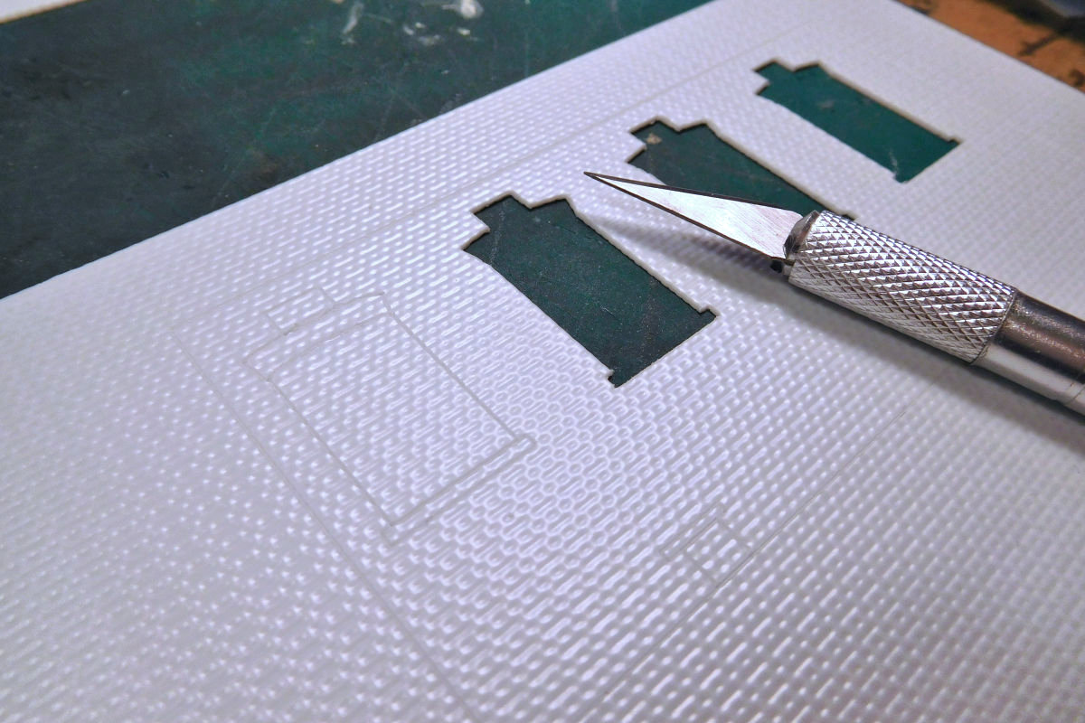
The Silhouette can't cut 20 thou, which is a problem if you’re using embossed sheets, since most of these seem to be of that thickness, including the SE Finecast sheets that I favour. So I used the Cutter to score the rear side of the sheet, and then cut through manually with a scalpel.


33351206746_0f053a8f15_o.jpg


The cut sections were laminated onto further layers to create depth. I ended up with five layers in total. The front of the building was done before I discovered that I could cut the full length of the building in one go.


33158292024_2afa9493e8_o.jpg


The vents, lintels and sills were also cut on the Silhouette. This is where it started feeling like making your own kit.


33391701105_9ba6e5028d_o.jpg


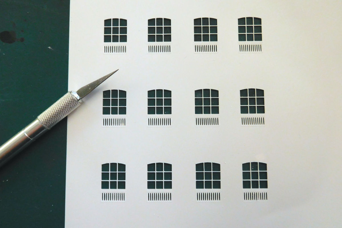
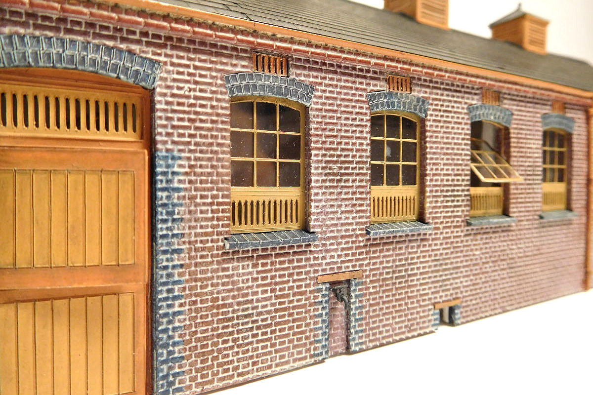
I initially struggled a bit to get the windows cut well. The silhouette isn’t really designed for this sort of detail work. The best I could manage was 0.3mm glazing bars. The hit and miss vents aren’t perfect, but once painted I think they came out OK.


33872051621_d1a941aec5_o.jpg


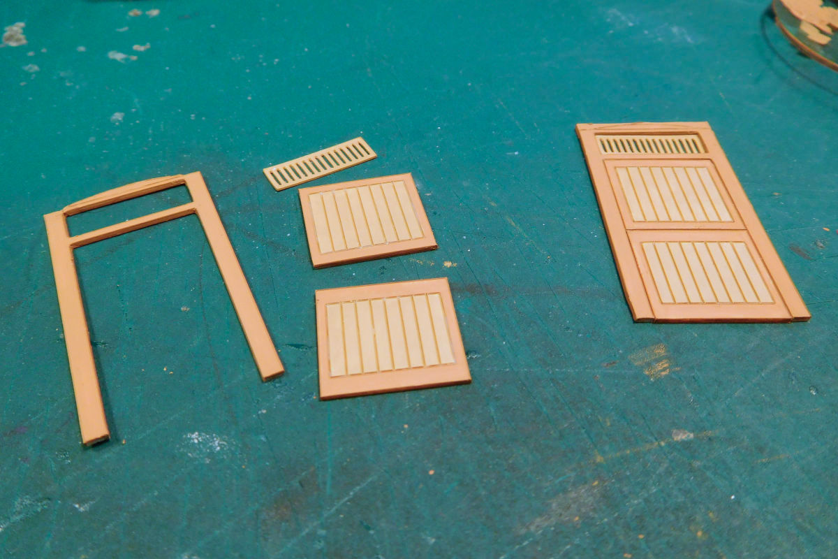
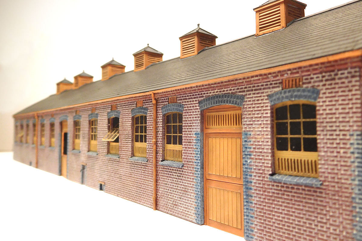
The doors were built up like this. They were quite tall and wide, which initially puzzled me until I realized that some rather big beasts had to pass through them!


33158291884_513bf96a32_o.jpg


The windows and doors were fitted as the middle layer in the 5 layer sandwich.


34001779365_cbaba09587_o.jpg


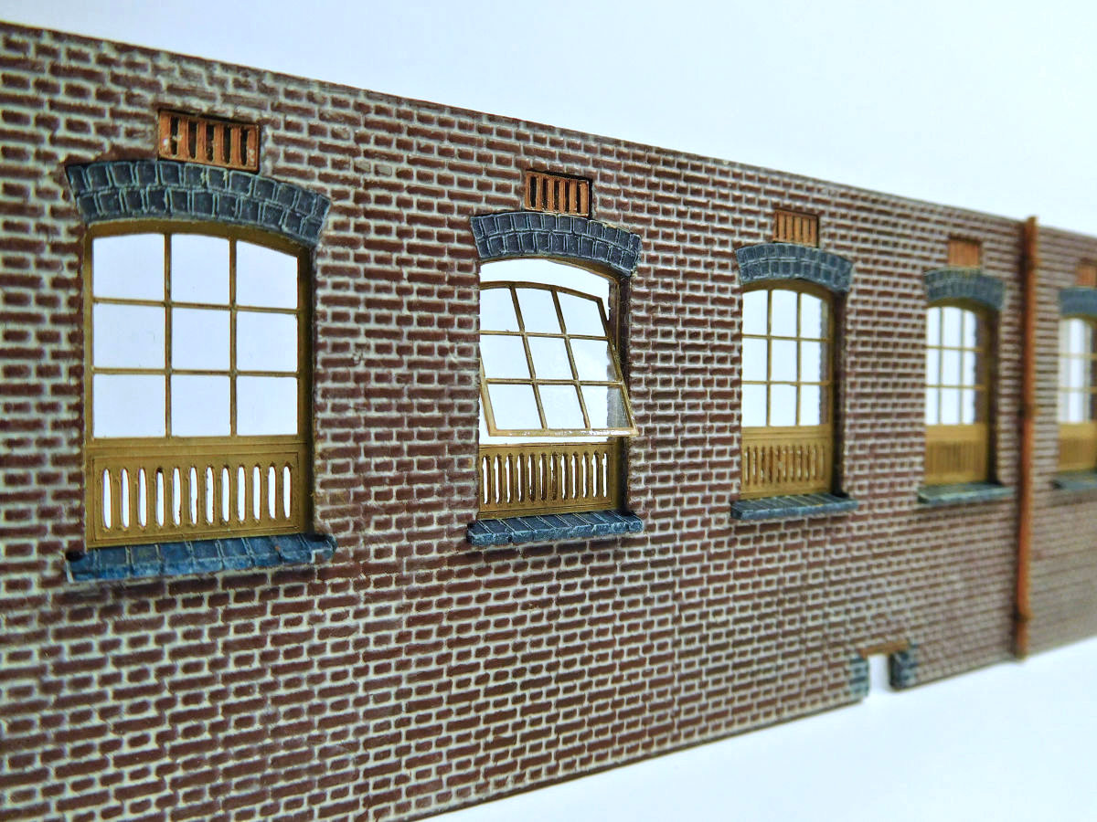
I modelled a couple of the windows in open position, to add signs of life.


34272917484_c095e60da8_o.jpg


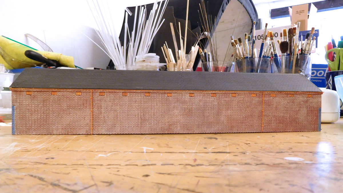
The rear wall was easy work. It was very plain on the prototype, as per most GWR stable blocks. I assume to give the horses a bit of peace and quiet (windows were sometimes retro-fitted when the stables were converted to garages).


34952666902_579e89a112_o.jpg


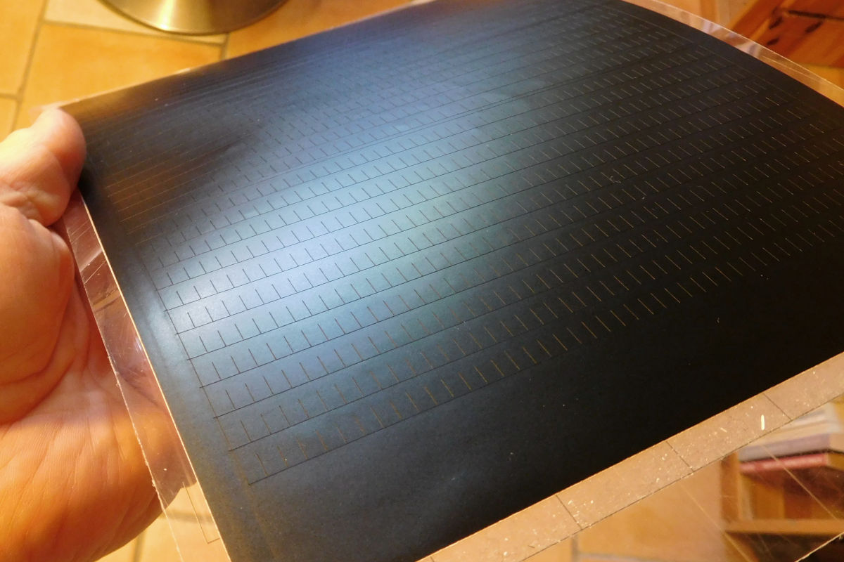
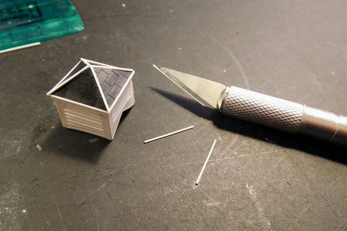
The slates for the roof were cut from vinyl, a tip I got from Lee’s blog.


34307233803_64e4bddba3_o.jpg


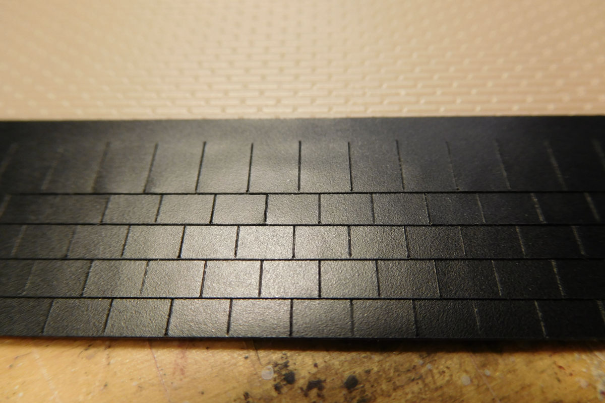
Once cut, the vinyl strips can easily be pulled off the backing and are not as fragile as paper or card strip, which allows repositioning.


34952667562_1b19f5a70e_o.jpg


Right, I thought, nearly done! But then came the roof vents…


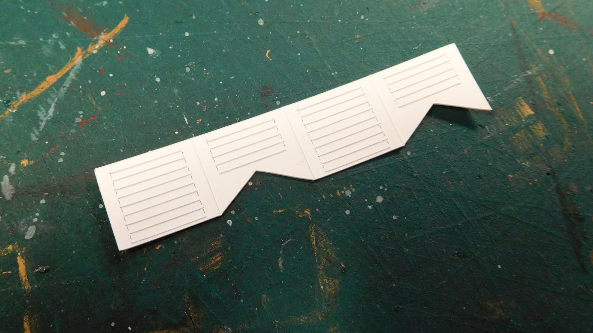
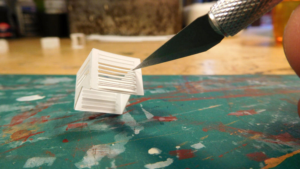
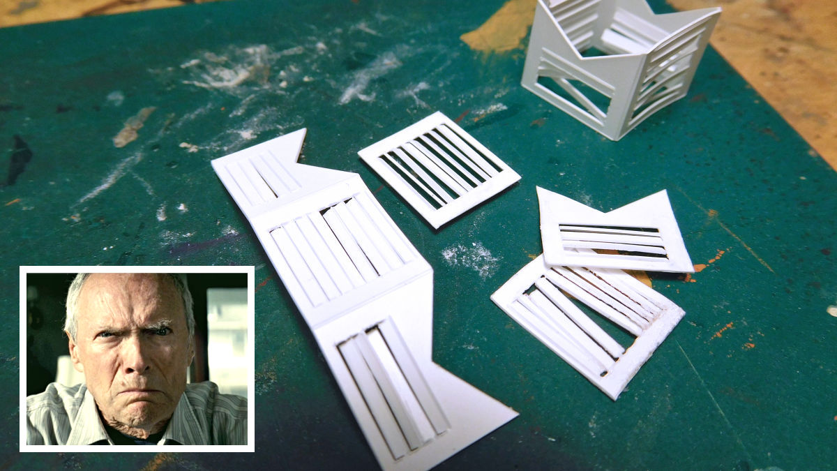
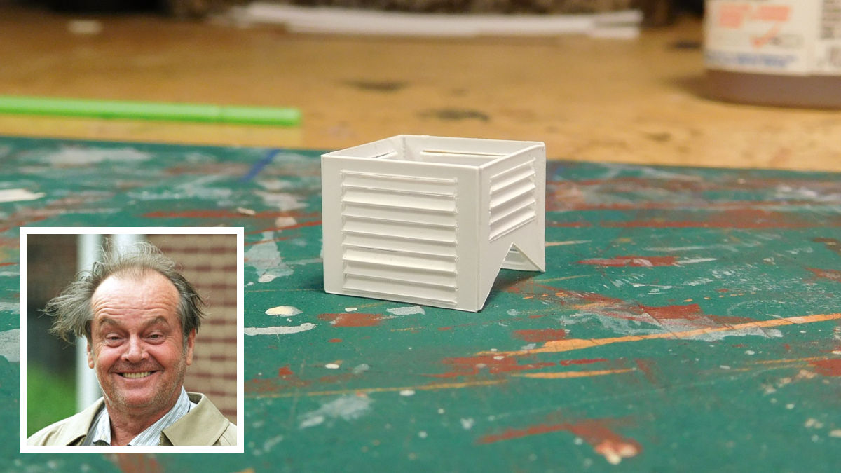
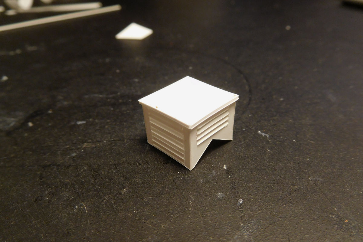
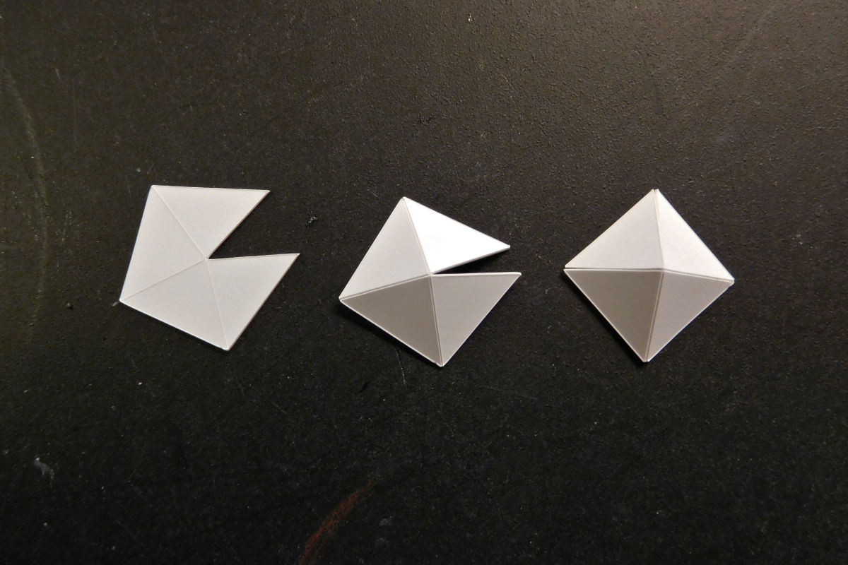
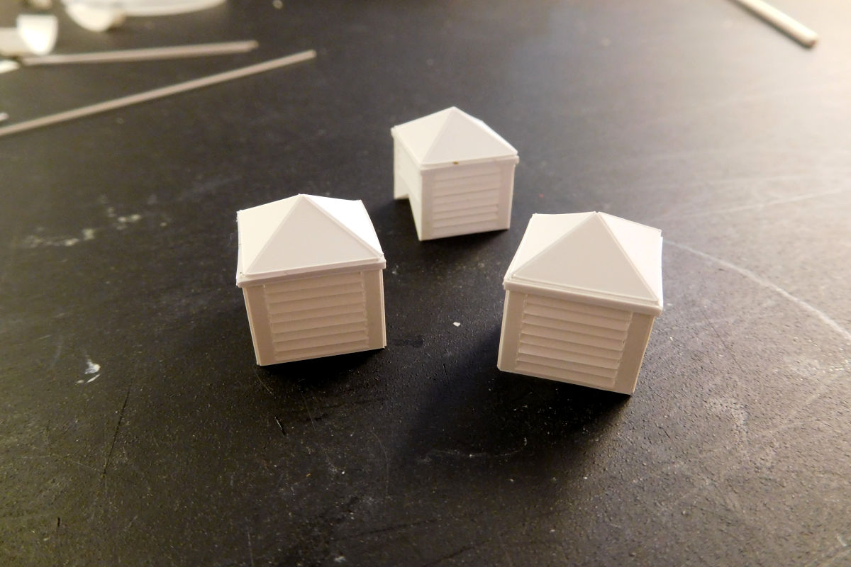
The roof vents – aka cupolas - turned out to be a whole project in themselves. I needed six, which eventually amounted to some 220 individual pieces. The photos below show how I made them. I hope they are more or less self explanatory:


34307233373_98b146cc41_o.jpg


34952666582_77a3e2557e_o.jpg


26617337209_53971b158b_o.jpg


26617339179_9275612f26_o.jpg


37199277444_f5d047e09b_o.jpg


37199277374_b1cf970c33_o.jpg


24057072038_00d29efbba_o.jpg


26132733059_d36dd6f0f4_o.jpg


37199277014_e1cb54c513_o.jpg


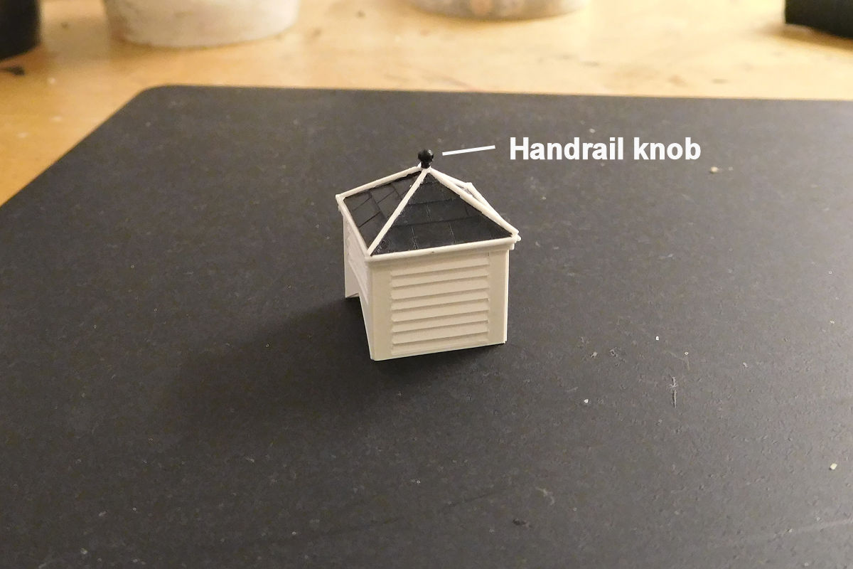
There followed a discussion in the workbench thread as to whether slate was actually used on the cupolas. Some photos *seem* to show it, but it remains an open question. The safe bet for anyone else would be to use metal sheeting instead, as several photos and one drawing shows this - although whether this was zinc, copper or lead sheeting is not clear to me.


38337786416_2c5c762b71_o.jpg


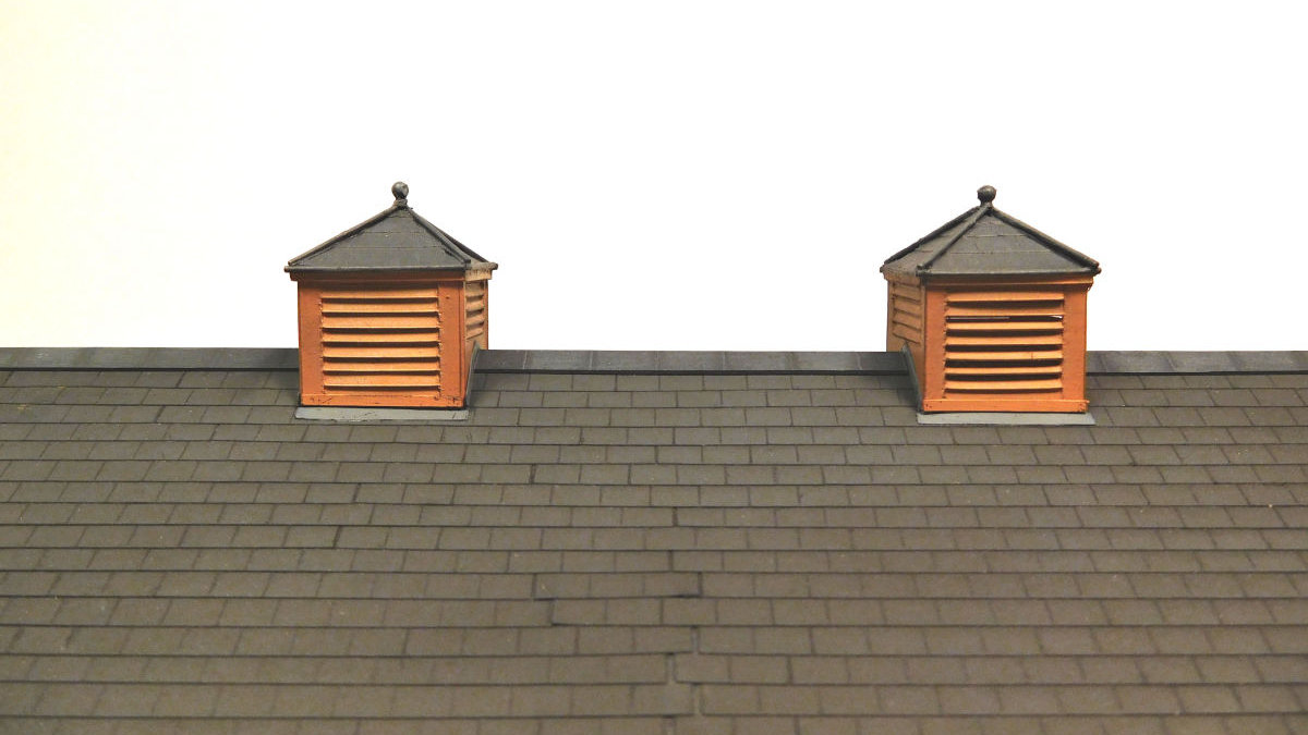
After painting, I realized that the individual slats in the roof vents had come out with slightly different angles. So my method for making them could be improved on. The camera is cruel though, and it's not that noticeable in real life.


26617333949_c4dd4728db_o.jpg
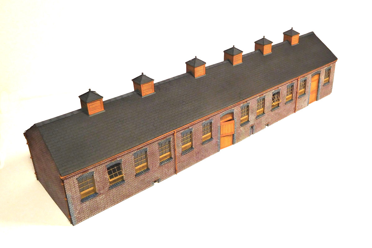
A view from above. The roof vents were not evenly spaced on the prototype.


26617313009_35faf971fc_o.jpg


26617322579_d81a2f7188_o.jpg


26617330039_36080e719d_o.jpg


26617309869_c91b4dbac3_o.jpg
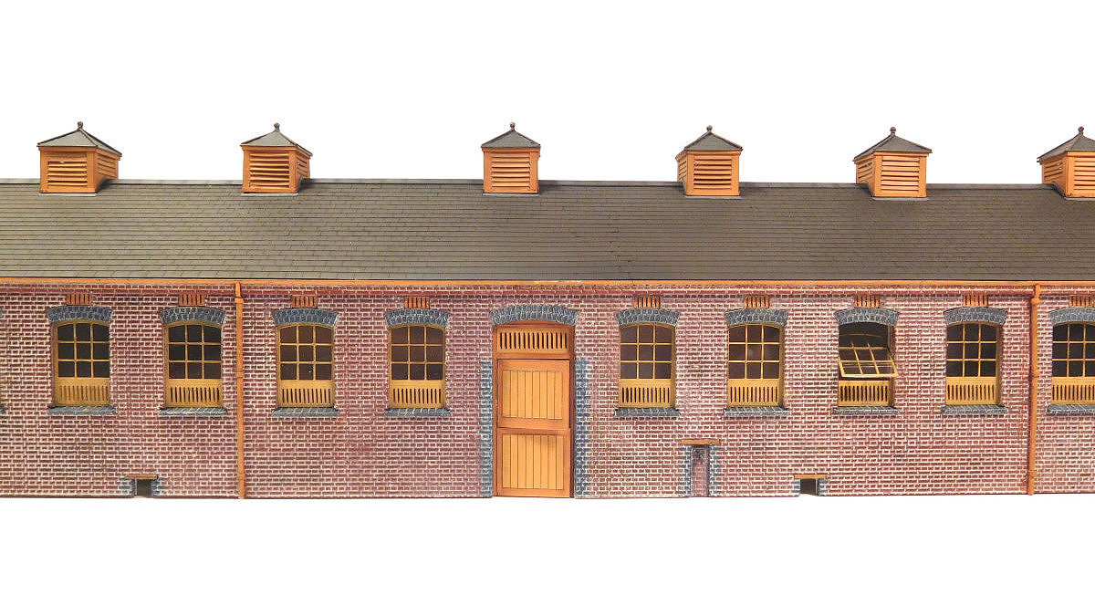
I have done a bit of light weathering, but it probably needs more. There is also the question of a manure pit, which I haven't built yet. I need to make some planning decisions first, more on that later.

  • Like 17
  • Craftsmanship/clever 5

40 Comments


Recommended Comments


What a stunning piece of work. Very well done indeed, a fantastic job which inspires me to pull my finger out and get on with Bricklayers Arms goods shed.

A very useful and inspiring post - thank you!

Link to comment
  • RMweb Gold

Really fabulous modelling Mikkel ;)


As for that work bench it looks like an F1 team's pit garage...Neat, tidy and methodical.


What is the next project as this one draws to an end?


Cheers,


Mark

Link to comment
  • RMweb Gold

What a stunning piece of work. Very well done indeed, a fantastic job which inspires me to pull my finger out and get on with Bricklayers Arms goods shed. A very useful and inspiring post - thank you!


Thanks very much Chris, I look forward to seeing your goods shed, with your skills and experience it will no doubt be extraordinary. 


Really fabulous modelling Mikkel ;)


As for that work bench it looks like an F1 team's pit garage...Neat, tidy and methodical.


What is the next project as this one draws to an end?


Cheers,


Mark


Thanks Mark, the tidyness of the workbench is completely accidental. At other times it looks like an F1 crash! The next project is to move on with the layout itself, including the backscene and a water tank. Plus, there's that Dean Goods.


Outstanding Mike an absolute work of art/


Hi Steve, many thanks, it's one of those projects that seemed endless while doing it, but afterwards not that bad really. The Silhouette cutter has helped a lot, although I'm also beginning to see its limitations. E.g. all those straight cuts can lead to a certain clinical look, which I think the stable block shows in places.

Link to comment

Very nice Mikkel.  I do like the "signs of life" with open windows and top stable door.  I think that the weathering is probably about right, after all in the Edwardian period the building won't be all that old.


Ian

Link to comment

Now I can see why your posts have been a little less frequent of late.  What a labour of love, though not without its 'moments', I am sure. 


It is also a good demonstration of the 80/20 rule where the remaining 20% (the roof vents) take up 80% of the effort.  Sadly, I usually come unstuck at that point and, hence, have a layout filled with 80% completed models. 


One of the attractions of modelling the earlier periods is that there are far fewer extra fittings (such as breaks) to worry about :)


I look forward to seeing this building in situ, surrounded by activity.

Link to comment

Mikkel, this is fabulous work and very interesting on various levels. I am planning a layout of Chippenham station and was worried about the stable block (plus many other things) and how it would have looked. I could not find anything of reference for this other than a footprint plan. Additionally I have been researching the possible use for a silhouette cutter for my buildings. Thank you for your inspirational modelling and blogs they are always a source of great interest.

Link to comment
  • RMweb Gold

Superb. You pass over the outside tap in silence....


Thanks Stephen. The tap is just made from bits of bent wire. I've seen a better and very clever way of making a tap somewhere one the web, but I've forgotten where! If I find it I will replace this one.


Very nice Mikkel.  I do like the "signs of life" with open windows and top stable door.  I think that the weathering is probably about right, after all in the Edwardian period the building won't be all that old.


Ian


Hi Ian, thanks, and yes I think you have a point about the weathering. Most of the stable blocks of this style seem to have been built ca 1900-1910, so mine would be quite new. Indeed, looking at various line histories etc suggests that during this time the GWR were on a drive to rid themselves of arrangements with local cartage agents in some locations and do the cartage work themselves instead - which of course then called for larger stables.  


Now I can see why your posts have been a little less frequent of late.  What a labour of love, though not without its 'moments', I am sure. 


It is also a good demonstration of the 80/20 rule where the remaining 20% (the roof vents) take up 80% of the effort.  Sadly, I usually come unstuck at that point and, hence, have a layout filled with 80% completed models. 


One of the attractions of modelling the earlier periods is that there are far fewer extra fittings (such as breaks) to worry about :)


I look forward to seeing this building in situ, surrounded by activity.


Interesting Mike, I hadn't heard about the 80/20 rule before - but it certainly sounds familiar! Those roof vents definitely contributed to the swear box, if I ever do something simialr the concepts needs further development!


It will be fun to populate the stables with horses and handlers (outside I mean, not doing it inside!). And it needs setts outside too, according to the drawings.

Link to comment
  • RMweb Gold

You're going to need at least half a dozen more horseboxes to do justice to that...


I do actually have a small collection of GWR horseboxes, a weakness of mine!


But if a cartage horse ever travelled by rail, it would have been by a lowly cattle wagon I think. Twelve stalls is a fairly big stable block, but not unlikely for a junction station like Farthing.

Link to comment
  • RMweb Gold

Mikkel, this is fabulous work and very interesting on various levels. I am planning a layout of Chippenham station and was worried about the stable block (plus many other things) and how it would have looked. I could not find anything of reference for this other than a footprint plan. Additionally I have been researching the possible use for a silhouette cutter for my buildings. Thank you for your inspirational modelling and blogs they are always a source of great interest.


Glad to hear it may be of use. The GWR stable blocks have been a bit ignored in my view, especially the larger ones. Let me know if I can help in any way with drawings etc.


I'm not sure what size and style the Chippenham one was, it will be very interesting to see what you come up with. I have found some additional stable blocks via the Britain from Above site, but haven't looked for Chippenham.

Link to comment
  • RMweb Gold

Thanks very much Paul, how about a large stable block on Lugsdale Rd? Or is that too old fashioned for the LMS!

Link to comment
  • RMweb Gold

Just fabulous Mikkel!  I'm sure the Farthing elephant is looking worried, that's another big chunk you've bitten off him! :-)


Looking forward to seeing the building settled into its surroundings.

Link to comment
  • RMweb Gold

Haha, thanks Dave. Step by step and all that. Speaking of which, I need to sort out whether the stable block actually goes on the current layout (the sidings) or whether it's better on the next one instead. This has been happening to several of my buildings recently, I need to get the plan sorted and bring the elephant back in the, er, fold!

Link to comment
  • RMweb Gold

Absolutely superb modelling Mikkel :good:


This entry, as always was a pleasure to read and see how you achieved the details - I do like the nice touches of the windows slightly open.


Looking forward to seeing it sat in its context soon!

Link to comment
  • RMweb Gold

Great architectual modelling. 


Thankyou Job, I do wonder sometimes if I should build in card like you - but my experiments withb that so far have not gone well! 


Absolutely superb modelling Mikkel :good:


This entry, as always was a pleasure to read and see how you achieved the details - I do like the nice touches of the windows slightly open.


Looking forward to seeing it sat in its context soon!


Many thanks Pete! I actually wish I had left more windows open, and the second door too maybe. BTW I was debating whether to add window openers (is that the word), but I wonder if a pulley system may have been used instead. 

Link to comment
  • RMweb Gold

I actually wish I had left more windows open, and the second door too maybe. BTW I was debating whether to add window openers (is that the word), but I wonder if a pulley system may have been used instead. 


You might be right Mikkel - but I would have thought a pole with a metal head on it was probably used on these...

Link to comment
  • RMweb Gold

You might be right Mikkel - but I would have thought a pole with a metal head on it was probably used on these...


Aha, thanks for that Pete. Which I suppose means nothing would be visible from outside...

Link to comment
  • RMweb Gold
Aha, thanks for that Pete. Which I suppose means nothing would be visible from outside...


Yep...


Thanks to A-ha too :jester:

Link to comment

Create an account or sign in to comment

You need to be a member in order to leave a comment

Create an account

Sign up for a new account in our community. It's easy!

Register a new account

Sign in

Already have an account? Sign in here.

Sign In Now

×
×
  • Create New...