


Ben Alder
-
Posts
3,198 -
Joined
-
Last visited
-
Days Won
17


Recent Profile Visitors


.thumb.JPG.b1d119c83fcf76d95704c93bba60b911.JPG)


Ben Alder's Achievements
14.3k
Reputation
Bookmarks
-
Imaginary Locomotives
Imaginary Locomotives2 minutes ago, Gibbo675 said:Hi Mr Goldfish,
The tractive effort calculation for a two cylinder is as follows:
TE = ( d X p X s / w ) X .85
- d = Piston diameter in inches.
- p = Maximum boiler pressure in pounds per square inches.
- s = Stroke of piston in inches.
- w = Wheel diameter in inches.
For four cylinders multiply the answer by two and for three cylinders by one and a half.
I would have worked it out but you have not furnished us with leading dimensions as noted above.
Gibbo.
Cheers Gibbo, tbh I'm none the wiser really! However I have lied a bit above and did have another play with sorting out a 2-8-2 wheel base based on the black 5 drivers and the revised DoG Mikado is below. Everything is standard DoG and what ever its 3 cylinder dimensions are, but with whatever size Black 5 drivers are!

It needed to gain an almost unnoticeable couple of inches of length to the smoke box to fit the new wheel base, but that's the only difference to the body of the original engine. I'm much happier with this than the version using 8f drivers.
-
Cobbles
CobblesCame across this in a Facebook group. For use on DAS clay, but I suppose it could be used on other types of filler. https://www.modellbahnunion.com/RAILNSCALE-H9538-H0-Strassenbelag-Walzen-Set-Strasse-und-Strassenbahn-2x.htm?SessionId=&a=article&ProdNr=RAILNSCALE-H9538&p=802
-
Adam's EM Workbench: Farewell for now
Adam's EM Workbench: Farewell for nowI've made a start on something new, though it is (yet another) brake van. This one is an early LMS vehicle, heavily inspired by Midland thinking and derived from a Parkside kit. This will be modelled as M802, pictured at York in 1963:
https://www.flickr.com/photos/blue-diesels/46498277551/As you can see, it's piped rather than vacuum-braked (the brake pipe is white indicating that it's through-piped) and unlike the 'pure' Midland vehicles built by the LMS has a ducket and ends with the sheeting on the inside of the framework, a design feature probably discontinued owing to water ingress at a guess. The Parkside kit of course is for the slightly later dia. 1657: https://paulbartlett.zenfolio.com/lmsbrakevan/h25187C05#h25187c05 [before the familiar longer-framed versions came in there was a final version of these vans with plate W irons and a 14' wheelbase - as opposed to the 12' here - for the LMS brakevan completist] but the main modification needed is in reversing the ends so I started there.

The new sheeting is scribed 20 thou'. For scribing I use the tip of a scalpel blade and a small engineer's square. Note that I cut the strip slightly over height and trimmed it down before fitting. As it turned out, I neglected the fact that the veranda screens on these earlier vans were lower. Here's what they initially looked like before I corrected them:

A comparison between the dia. 1657 and whatever this diagram actually is this morning. The confusion over which diagram it is arises from the fact that Paul Bartlett ascribes a couple of different options, 1656 or 1658, to similar vans and I don't have the Essery books to hand to check (it doesn't much matter to me for the purposes of making a model from a fundamentally accurate kit and a good clear photo).

Note that, like Geoff Kent, I've added a bit 0f 10 thou' by 30 thou' strip to beef up the springs. The other thing - that I dimly recalled from reworking the earlier, unfitted van - is that the bearings need to be inset a fair way to ensure that the solebars are parallel when you put the wheels in. THIS IS IMPORTANT! A few twists of a 1/8" drill were needed and the flanges of the pinpoint bearings should be inset rather than proud or even flush to achieve free-running with this kit.
Adam
-
Unable to post, start new topics etc. with Firefox
Unable to post, start new topics etc. with FirefoxIt could be a change in the location of some of the javascript files. I noted that I now need to add cloudflare.com to NoScript in Firefox to get things to work properly. Initially when the site was upgraded this wasn't necessary.
-
Langford Lane & Marlingford - GWR 1940s Oxfordshire
Langford Lane & Marlingford - GWR 1940s OxfordshireOne of several projects on the go at the moment is a more appropriate autotrailer for the branch line. Photos of the real Woodstock branch show trailer 110, a matchboard side trailer diagram A7 being used post war. Having seen what Simon Dawson, Rue_d_etropal of this parish, could do with 3d printing http://www.rmweb.co.uk/community/index.php?/topic/124562-dear-hattons-time-for-a-proper-autocoach-please/?p=2886454 with a diagram Z trailer, he kindly made the modifications to get an A7.
Simon's Shapeways shop can be found here https://www.shapeways.com/shops/recreation21
Here is the model as received from Shapeways (and the world's messiest workbench!). It is in what they term their White Strong and Flexible material, I don't know the technical details.
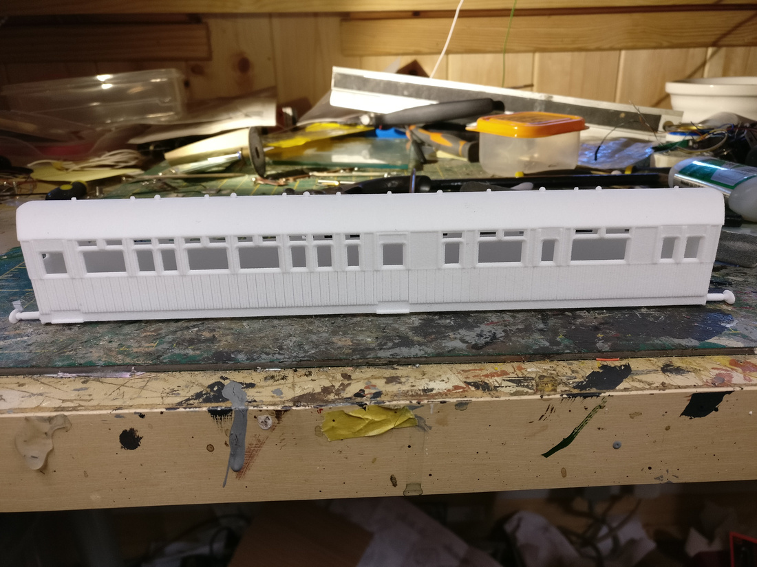
The material is not smooth so bit of research on this site suggested using Halfords plastic filler primer then sanding down and repeating a few times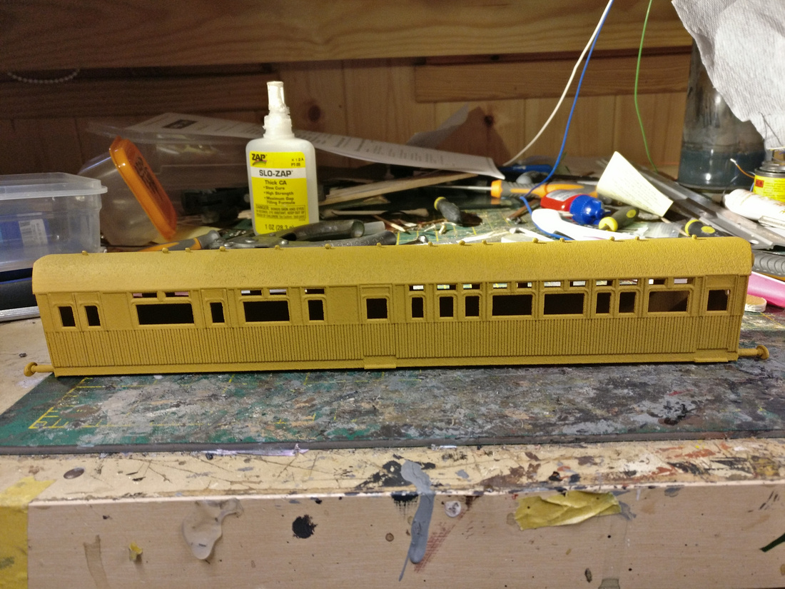
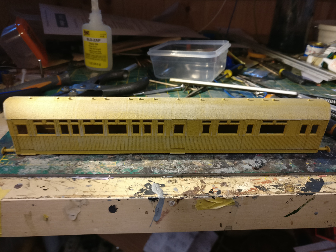
I've made a bit more progress since these photos, will post details of this anon. In the meantime, thank you for the interest shown and encouragement given and I wish you all a good Christmas.
All the best
Jon
-
Hornby T9 Motor Meshing Problem
Hornby T9 Motor Meshing ProblemI had a problem with a T9 and there were two issues. One as described above was the casting fracturing, stopping the gear mesh between the idler gear and worm. This was resolved with a Peters Spares replacement. The second issue I eventually discovered, was that the final drive gear had moved sideways on the axle, so losing contact with the idler gear. The centre part of the axle has splines which grip the boss of the gear. This I cured with a tiny spot of super glue, ensuring first there was no oil or grease present. Stripping down the chassis to get at the gear train isn't easy with tiny wires and pickups getting in the way. To be honest, it's a real pain, but with steady nerves and patience it can be resolved. It took me several attempts before I cottoned on to the loose final drive gear issue.
So if your loco motor spins happily, but the loco doesn't move, then you know now where to look!
Have fun, keep the faith and your patience!!
Tod
-
Hornby 5MT derailments
Hornby 5MT derailmentsWhen I detailed a Hornby Black 5 using the Brassmasters kit etc. I found that the bogie was prone to derailing after I fitted Alan Gibson bogie wheels. I added a soft spring which I think was cut down from the ones Bachmann use on bogies for their locos, which is soldered at the bottom to a washer attached to the bogie by a nut and bolt through the pivot. The top of the spring locates over the white plastikard square which can be seen on the bottom of the mechanism between the cylinders. As you can see I also glued some lead over the front of the bogie. Possibly I had unbalanced the bogie by sawing away the coupling mounting, but the spring also has enough of a centring effect to stop the bogie wheels from conflicting with the front steps.

-
Blog Management
Blog ManagementThe sidebar feature can be switched on in Manage Blog >> Edit Blog. But if you haven't saved the old index, you'll have to rebuild it.

-
HIGHLAND RAILWAY TRACK
HIGHLAND RAILWAY TRACKI have, over recent months, been taking an interest in this topic and have been counting sleepers on a large number of photographs in the Highland Railway Society collection (I lead an exciting and enriching life). Forbye the rail lengths mentioned by Graham R in his posting, which gives the lengths of rails in some early constituents of the Highland, I believe that by around the 1890s, the HR standard track was using 30 foot long rails with 11 sleepers to the rail. Most photographs on HR metals show this well into the grouping. This ties in with the drawing at:
http://www.oldpway.info/drawings/1895pw_pl16_HR.pdf
This is a drawing from an 1895 publication and shows rail of varying cross-sections of 76½, 77 and 80lbs/yd. The 76½ lbs/yd section looks awfully like a double headed rail to me; the other two are definitely bullhead.
However, there are a few photos which show 10 sleepers per rail length. There is also one which shows 8 sleepers per rail length in LMS days (at an unidentified location but it shows Mackenzie and Holland signals, so almost certainly ex-HR). I doubt that this would be 30 foot rails. I have also recently found one photo which shows 12 chairs on each rail, but only 11 sleepers per rail length. How was this remarkable feat achieved? By use of joint chairs at each end, that's how. "Jings, crivvens!" I hear you say. You can have a look for yourself at:
The bottom right hand corner shows a joint chair. Count back from there, if you have nothing better to do.
The use of joint chairs is confirmed by:
http://www.oldpway.info/drawings/1905jt_d42_HR_supported.pdf
This drawing is signed by Mr Roberts in 1905 and shows the use of 90lbs/yd rail. This is quite an increase from 10 years earlier, but it would tie in with the introduction of heavier rolling stock and locomotives at that time and ties in with the general development of British permanent way.
My thoughts are that, once the use of 30 foot long rails was introduced, the Highland used 10 sleepers per rail length for a while, but later used 11 sleepers per rail length. I have not seen any evidence for the use of longer rails on the HR. (This has to be treated with some care, as longer rails would tend to not show their full length in a photo, so the number of sleepers couldn't be counted; I hope that makes sense.) My view is that the use of 30 foot rails continued to the end of the HR. Given the low volumes of traffic on the HR generally, they would remain in use for a long period after the grouping.
On my own layout in 2mm, I have opted for 11 sleepers per rail length on the main running rails, with 10 sleepers per rail length in the yard.
Incidentally, there are a good number of photos of HR trains on the CR between Stanley Junction and Perth. A few of them show 14 sleepers to the rail length. But that was CR track, I presume using the CR standard of 32 foot rails (later 48 feet).
Fascinating stuff! It's remarkable how little attention most modellers give to the permanent way. Without it, there would have been no railway. Locomotives were only replacements for horses, so we could still do without them.
Back to my sad and lonely existence. One sleeper, two sleepers, three sleepers, four sleeper - ooh! look at that lovely bit of ballast...
-
Coal Stacking at MPD's
Coal Stacking at MPD'sPrompted by a brief conversation with Mike 'The Stationmaster' at Fawley Hill, I have been giving some thought to the practice of stacking loco coal on the stages at larger sheds. This appears to have been particularly prevalent on the Great Western, as the images below at Newton Abbot show.
This method of forming a robust outer wall, behind which the reserve coal would be stored and contained would put many artisan dry stone wallers to shame. It must have been incredibly labour intensive for the Coaling Gang, already regarded as one of the most back-breaking jobs.
It would be interesting to hear any anecdotes or observations about this unusual process, or to uncover detailed photographs of it in action.
Regards,
Andy.


-
LMS Period 1 Coaches
LMS Period 1 CoachesHi
Could you make a full third from 2 brake thirds?
Ian
No, because the corridor side is different (and two Brake Thirds would leave you with the toilet at the wrong end of the compartments for one end). It's easier to just alter the corridor side of a Composite - see my post no.12 above. The compartments from a Brake Third could be spliced in with the Third Class ones of a composite, but some sideways adjustment will be needed as the toilets at the ends of Composites and Brake Thirds are not quite the same size, hence my suggestion of 'faking it' on the Corridor side only. On most layouts you don't get to see both sides of coaches.

Also one coach is cheaper than two!
-
Eric's Chop Shop - The Carriage Works - moving on to LMS Vestibule Stock
Eric's Chop Shop - The Carriage Works - moving on to LMS Vestibule StockTo help finding stuff as I go along I am adding a list of stock featured in this thread. It will be updated as further items are added.
1) LMS Period 1 D1695 Corridor Third
2) LNER D186 / D302 Open Third (added 5th June 2020)
3) LMS Period 1 D1755 Brake Composite (added 23 December 2020)
4) LMS Vestibule Stock - BTO D.1746 & D.1913, TO D.1692, D.1807 & D.1915 (added 29 December 2020)
Now that the summer activities are well and truly past it's time for completing some ongoing projects and starting some new ones. First up is a bit of plastic surgery attempting to fill a gap in the Mainline / Replica / Bachmann models of the LMS Period I All-Door Corridor Stock. The prototypes were some of the first coaching stock built by the LMS and were heavily based on the existing Midland Railway designs. They were the last 'All-Door' corridor coaches built by the LMS.
LMS Period 1 'All-Door' Corridor Third - D1695
Many years ago Mainline issued LMS Period 1 Corridor stock in the form of the all-door Brake 3rd and Composite. For their time they were quite a nice model and were subsequently improved by Replica Railways then Bachmann.
Unfortunately none of the manufacturers ever got round to making a Corridor 3rd, although this was probably the most numerous of this series of coaches.
There have been discussions on other threads about the viability of a cut'n'shut to produce one of these but the idea had largely been dismissed. The gangway side was simple as the only difference between the TK and CK was a window in place of a blank panel. The compartment side was considered to be too difficult.
I had been researching in order to build a 57ft BG as converted from the LMS WW2 Ambulance Trains, which were themselves converted from Period 1 BTKs and Cks. I had a Mainline version of each which were to provide donor panels. When I put the two on the workbench with the compartment sides towards me I had a Eurika moment. There were enough third class compartments to make up a full coach and a toilet window at each end.
These were the two coach bodies I had in mind for the 57' BG conversion. As they were to be more or less destroyed I decided to use them as panel donors for the TK.

For the next pictures I have used a couple of Replica / Bachmann coaches to show the panel cuts required.
Firstly a demonstration that the job was possible on the compartment side.
I decided that I would cut the whole compartment side out of the donor being used for the final vehicle, but leaving the ends intact.
As I hadn't done a modification of one of these bodies before I started with making the easy bit. The next picture shows the area I cut out on the corridor side. I did two windows as it meant that the left hand side could be cut at a door, thus not leaving another join line to fill and smooth off.
The donor panel was cut leaving a bit extra on the right side to be finished when the gap had been cut in the side.
The panel was then test fitted to the hole cut in the side of the donor body.
That successfully completed it was on to the corridor side. The required sections were cut from the donors at a door line to ease later filling and laid out together. The are slightly too long but the compartment spacings are correct. The extreme right hand window on the Brake vehicles is slightly smaller than the rest and the panels round the toilet windows are not quite correct but the variations look to be less than 1mm from the drawings in David Jenkinson's books.
The side was joined together and test fitted to get the right length. The important thing is to get it centred correctly and not try to work from the ends.
Somewhere during the whole process the original roof vents were removed, holes filled and rubbed down then a new set of vent fitted to match the new compartments.
Painting has to be touched up a little and I'm not convinced by the black on the roof edges but it's getting there.
-
Hornby T9 broken motor housing retainer
Hornby T9 broken motor housing retainerRight, well having completed the repair process, some notes for anyone interested.
The first thing is that the Peters Spares casting , whilst sturdy and well made, does need a fair bit of "fettling".
To start, there is a casting nib from the mould at the front end, easily removed with a hacksaw and dressed with a file.
The lower edge of the worm cover (the front part of the casting), should be parallel to the rear section on which the motor sits. Mine wasn't, and I bent it by hand to comply, albeit with trepidation as its the weak bit that failed on the original that needs to move.
The back end of the worm cover needs to be filed out so as to just rest on the top of the front motor bearing, I did this a bit at a time and kept testing. This will allow the motor to sit flat on the rear part of the mount.
The two lugs in the centre, bottom of the casting need filing out to just push comfortably into the notches in the chassis. These secure the new casting from below to the chassis.
The rear of the casting may need dressing to allow the rear mounting plate to sit vertically. This holds the motor by fitting over the rear motor mounting.
You should now be able to ease the motor into the casting, and attach them using the central lugs to the chassis.
The rear mounting plate can be screwed in, remembering that the wire to the lower motor terminal fits through a hole in the plate.
I found the wiring to be a nightmare, there's little space for all the wires and they come together on a small soldered board, before going off to the tender via "Satan's plug". The wires are very thin, presumably for space saving, and easily break at the soldered joints. I had detached the wires from the motor at the start, you can't do any of this otherwise, the tags on the motor are also very fragile and seem likely to break off at any time. Anyhow, eventually it all went back together, the chassis fitted into the body, and the loco runs very smoothly!
There is very little play up and down in the front bogie, and it can only be tweaked whilst the body and chassis are separate. The securing pin from the bogie into the chassis seems too long, and I cut a bit off, at the same time chopping the bogie spring in half and only refitting one part. There's now more up and down movement possible, so no question of the driving wheels not being in contact with the rail, but I may have overdone it as the bogie wheels don't rotate as freely as I'd like, probably due to pick-ups rubbing on all four wheels.
Maybe I'm just getting past it, but this is certainly not a walk in the park!
John.
-
Hornby T9 Motor Meshing Problem
Hornby T9 Motor Meshing ProblemThe flaky mechanical design of the front clamp cum worm cover on this and the other contemporary Hornby steam mechanism designs has led me to glue in the motors using Evostick. That completely relieves the clamp from taking any mechanical load. I have never had a T9 to look at, but on all those I have tinkered with there's a good contact area available between motor casing and the main casting to ensure adequate bond strength. Ensure the bond has fully gone off by 48 hours in an airing cupboard or similar warm location before attempting operation.
-
Kernow Adams O2
Kernow Adams O2Hi Chris,
And in fact everyone else with an O2 model.
I've spoken to China about the body removal, and as is the norm with these things, i have an answer to the body removal issue from them and i paste here.................
In production, the body is not glued to the chassis while the pipes are. After removing the screws, the body can be tilted slightly, before breaking the pipes (but is less than 45 degrees). Actually, this model is not designed for opening the body. If for any reasons it has to be opened (e.g. repairing, or replacing parts inside), the two pipes will have to be cut (at where they meet the chassis). After repairing, if preferred, these can be glued with a drop of super glue. On mass production, just one point will glue may be easy lose off.[/size]
So there we have it. the pipes are glued, and the body is not designed to be easily removed, because doing so would invalidate warranty and require the cutting of the glued joint on the pipes.
I also attach the pdf of the wiring diagram for this loco for those that need it.
Hope this helps?
cheers
Dave
I'm sorry Dave but there is no way that it is just those thin pipes stopping me removing the body.
When I lift the rear of the body up the splashers and footplate all come up as well.
I assume there must have been a very good reason why you did not design the body and footplate to come off as one assembly?
As it is these loco appear to be sealed units.
-
Kernow Adams O2
Kernow Adams O2Same as me, when I lifted Ventnor off for wheel cleaning a few of months ago, the bogie was left on the track. No sign of screw or spring but could have been missing for ages, track cleaned and vacuumed once a week and lots of it. Runs OK without being properly attached, but no back-up for spares it seems.
I have some positive news! The screw in question is used in a number of the places on the O2. I removed the one which is screwed into the chassis underneath the bunker (i.e. just back from the trailing bogie mounting). It does not seem to have resulted in the model falling apart. I bought some steel compression springs from Eileen's Emporium (Steel Compression Spring 4.0mm Long 3.0mm Dia 10 Pack SPRC300), one of which seems to have done the job.
Chris
)ompression Spring 4.0mm Long 3.0mm Dia 10 Pack SPRC300
-
Nile's Mostly Freelance Bodging Bench - Pre-Grouping Locos
Nile's Mostly Freelance Bodging Bench - Pre-Grouping LocosRecently what little energy I have in this heat has been directed elsewhere. Then suddenly last weekend I got the urge to tinker with one of Oxford' Rail's Adams Radials, to see if the motor mount problem could be solved without too much work and new materials. The problem with the model as it comes is that the motor mount protrudes into the space under the front part of the boiler. The solution is to move the motor rearwards , doing this with the original motor isn't entirely simple.
This is the starting point. Between the motor and gear tower are a flywheel and universal joint, these will have to go.
With the wires unsoldered the motor can be removed from its mount.
The motor and flywheel. One half of the universal joint sits in the recess of the flywheel, which is very firmly attached to the motor shaft.
It might be easier to use a different motor, my previous conversion used a Mitsumi motor seen here, still available on ebay. Another alternative is in the photo, a 5-pole motor also from ebay, but I don't know if it's still available.
My intention this time is to reuse the original motor, which means getting the flywheel off without breaking the motor.
More tomorrow, time for bed now.
-
Nile's Mostly Freelance Bodging Bench - Pre-Grouping Locos
Nile's Mostly Freelance Bodging Bench - Pre-Grouping LocosThe problem here is that there isn't enough room to get my gear puller between the motor and flywheel, so I resorted to attacking the flywheel with saws and drills. This was the sight part way, note that I've wrapped sticky tape around the motor to keep the brass out.
The motor has a 1.5mm shaft, whereas the worm is on a 2mm shaft. To bring these together I used some brass rod, 2.0mm O.D., 1.5mm I.D. The bearings needed opening out slightly to fit on the tube.
Edit: The tube and worm were secured in place using Loctite 603.
Here it is fitted to the chassis. There is a piece of wood under the motor, it might be from a lolly stick, it will stop it rotating. The motor mount has moved to the left, lining up with the next hole in the chassis.
After a test run proved successful I tidied things up. Most of the motor mount was removed, and the clip was refitted onto the gear tower.
This brought things to a halt, it seemed the clip over the gears was too tight. So I removed a small amount of material from both sides of the clip to loosen it slightly. This fixed the problem.
Finally for today a photo showing the chassis and body together, but without the boiler. This shows how far back the motor now is.
I've removed the boiler so I can add a new underside to it, that's next.
-
Orange patches on Van B
Orange patches on Van B1 hour ago, Wickham Green said: Intriguingly, there's a photo of a NON-Southern bogie van in https://www.amazon.co.uk/Historic-Carriage-Drawings-Vol-Non-Passenger/dp/1899816097 which seems to have similar patches - can't remember what it is I'm afraid ..... and no idea whether the significance is the same !
On page 15 there's a picture of a Highland 37' 9" bogie brake at New Street in 1954 with the bottom panel of the guards door and the extreme ends of the top panel painted in a different colour to the rest of the body. It also carries STOVE branding. Three vehicles were rebuilt to brake vans from older mail vans around WW1.
-
Oxfordrail - Adams Radial
Oxfordrail - Adams RadialAnyone else had problems with excessive wheel spin on the Adams? I have exchanged mine twice but still the same problem as the driving wheels have no traction and it comes to a grinding halt on any point or crossover - Peco code 100. I know that the response will probably be "its your track laying", but the track is good and many small tank engines, including a Hornby Peckett whistle along without missing a beat! And they can pull a coach or two or 4/5 wagons, which leaves the Adams at a standstill.
Many thanks,
Paul
Paul, are they from the initial batch? After the first batch, Oxford increased some clearnaces and the free play on the unpowered wheels because others had the same problem you are experiencing. There are some easy solutions in the earlier pages of this thread just after the models were released. Post #1296 on this page is about the right timeframe. http://www.rmweb.co.uk/community/index.php?/topic/91184-oxfordrail-adams-radial/page-52
-
SE Finecast
SE FinecastI think Dave ,a scholar and gent ,is still basically analogue.That should answer any snotty remarks from the digitally enabled but hardly well mannered sections on this forum .The man ploughs his own furrow and long may he do so .
-
Imaginary Locomotives
Imaginary LocomotivesSeveral pages ago before we started to get too mathematical in our imaginations, someone suggested a BR standard 2-6-2 based on the LNER V4 concept.

-
Imaginary Locomotives
Imaginary Locomotives4 minutes ago, Clive Mortimore said:Several pages ago before we started to get too mathematical in our imaginations, someone suggested a BR standard 2-6-2 based on the LNER V4 concept.
Hi Clive,
You could knock one of them up from a couple of Dapol Kits. A mix of class 4 and class 9 kits suitably spliced would do the trick.
You could use the class 4 main frames, boiler barrel and cab along with the class 9 firebox and tender. With the left over bits you could shorten the class 9 frames and make a 2-8-4 to go under the class 9 boiler barrel you could splice those together with the class 4 firebox and use the class 4 tender as the trailing truck and bunker. Perhaps even more crazy build the class 4 tender into a four wheeled semi articulated tender with a booster unit
Gibbo.
-
Nile's Mostly Freelance Bodging Bench - Pre-Grouping Locos
Nile's Mostly Freelance Bodging Bench - Pre-Grouping LocosSorry to go off topic, but curious. Yankee Tank?
diameter = 18.0mm
pitch = 29mm (centre line to rail top) as best I can tell.
Sorry to be so late on this - got distracted by other things
 and forgot about the Radial. Yes, thoughts about a Yankee tank, but it would be a bit beefier than the HR loco, I have discovered. Still, it might be a goer but probably one kept away from the camera.......If it happens I'll keep you informed.


