

Harlequin
-
Posts
5,604 -
Joined
-
Last visited
Content Type
Profiles
Forums
Blogs
Gallery
Events
Exhibition Layout Details
Store
Posts posted by Harlequin
-
-
Still thinking about options and convincing scenarios but inspired by Regularity's modifications and Barnstaple (Victoria Road) I came up with this possible variation:

Pros
- Extra goods/cattle siding
- More spacious feeling to goods yard
- Goods shed performs better as view blocker
- Still two sidings opposite gasworks kickback to make shunting a bit easier
- Goods shed line make full use of baseboard diagonal
- No major changes to signalling (!)
Cons
- Too much track?
- More track joints across baseboards
- Less opportunity to disguise baseboard joint
- May have to abandon clever perspective ideas about slightly different levels for goods and passenger lines
- May have to abandon remains of broad gauge train shed
-
 1
1
-
I have been looking at the info Regularity kindly sent me about Cardigan and searching for other relevant prototypes.
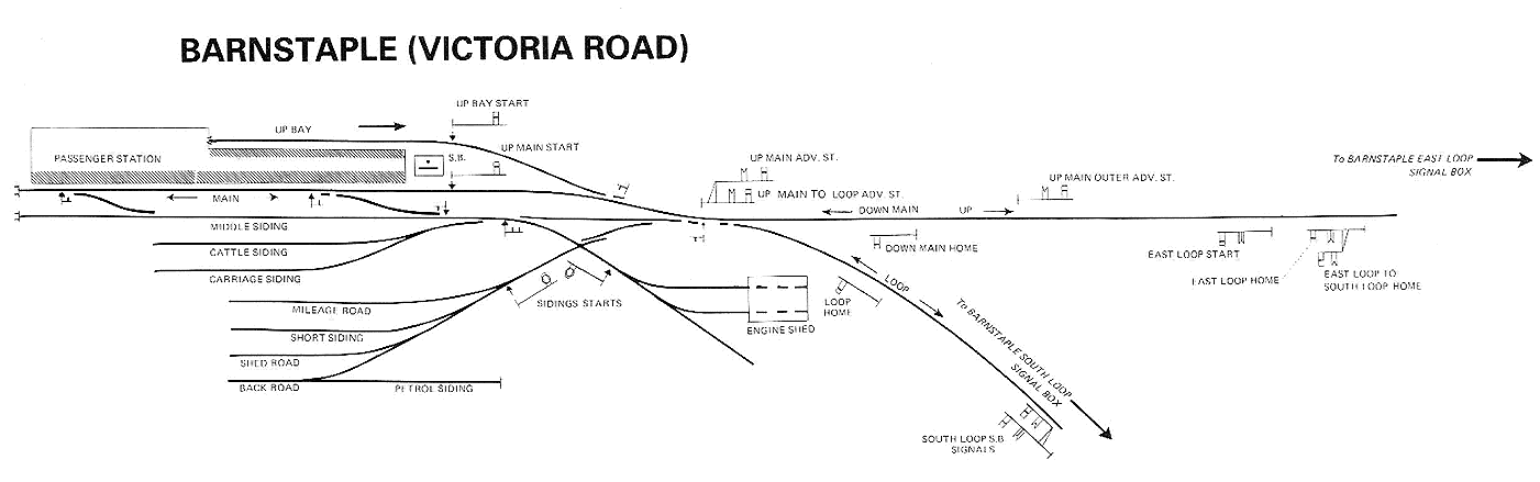
A very interesting example is "Barnstaple (Victoria Road)": http://www.greatwestern.org.uk/stat_1.htm
Barnstaple Victoria Road was a terminus originally built to broad gauge standards and later taken over by the GWR.
The links to the track plan and signal diagram on that page are not obvious (white on a cream background...) so I will repeat them here:
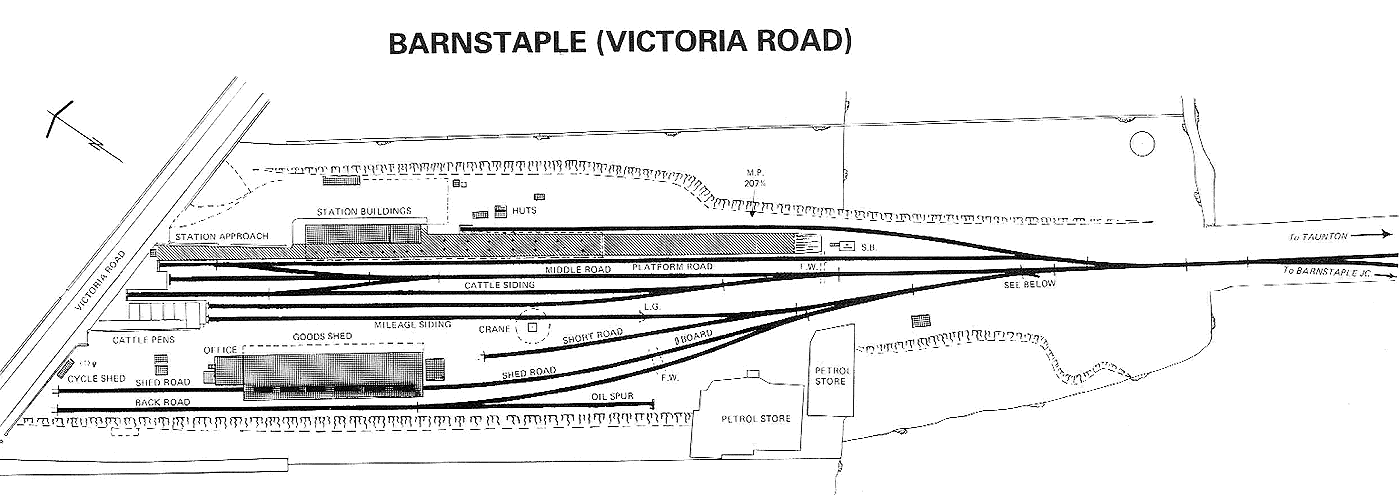
You can see that the basic topology is very similar to Hampton Malstead as currently conceived, even down to the difficult-to-shunt kickback fuel siding.
-
2
-
-
Very interesting! It's good to have my fixed ideas challenged and I can see pros and cons in your suggestions.
I'm going to have to think about this...
-
Hampton Malstead
<Imagine beautiful stylised design of trees, valleys, distant purple moortops, blue sky and, amongst it all, a small green loco pulling chocolate and cream coaches>
Gateway to Eden

-
3
-
-
Thanks for your thoughts and advice everyone.
I will rotate the diagram at some stage, adjust the lever numbering and see what I can do about the FPLs on the bay crossover. Luckily I have one spare lever!
I haven't yet devised a full back-story or thought about exactly what facilities lie further up the line (down the valley). When I do, things in the station might have to be tweaked but the basic idea for now is that Hampton Malstead is a thriving moorland town that serves villages for many miles around. Some of the ideas from earlier in the thread will be applied to justify the level of development at the station:
- The surrounding countryside is renowned for its beauty and variety and so has become a tourist attraction. (Maybe I should create a publicity poster...)
- There is a quarry a few miles down the valley that occasionally makes use of the station facilities because its own infrastructure is pretty basic.
- Point-to-point races are held nearby that regularly draw entrants and crowds from across the county. (So yes, I should give more thought to horse loading and unloading.)
The toe-to-toe turnouts in the goods yard straddle a baseboard join and so cannot be easily combined. Also, the trackwork is all rendered in Peco Streamline Bullhead so I'm restricted to using their large radius straight left/right geometries at the moment. Even the trap point will be a cut down large radius Streamline bullhead point. (I'm not ready to start building my own track yet.)
@Regularity: For me at least, part of the satisfaction of the layout will come from knowing that other people also find it satisfying. So I am listening intently to what everyone's saying! I hope that I haven't yet strayed into the realms of the unconvincing and I think I can justify my choices so far:
- Exactly modelling the prototype requires a lot of space, as I found when attempting to compress Moretonhampstead, hence the fictional location.
- I'm doing my best to obey the rules, not make exceptions, within the constraints of compression and the need to create something that is artistically pleasing (e.g. follow GWR signalling practice).
- I hope I'm stitching together typical features in a concentrated but realistic way.
- For me, the operational possibilities also need to be concentrated. A beautifully convincing model that only received a prototypical one train a day would be wholly unsatisfying to me. Hence, more than one engine in steam, the bay platform and the backstory.
If I ever "Jump the Shark" everyone should please shout at me!
-
2
-
Here's revision 32:

[Click to enlarge]
- Bay signalling and trackwork upgraded for passenger working.
- Better points symbols showing normal positions.
- Point indicators for engine release (14) and engine house siding trap (15). I had to make up a symbol for a point indicator.
- Small arms on brackets, possibly centre pivoted, reading from down main into goods yard (8) and bay platform into engine house (5).
Edit: If something like this drawing were to be used as the signal box diagram it would have to be rotated by 180 degrees, of course. But I can't face that right now!
-
1
-
Excellent! Thanks Mike, you truly are "The Stationmaster".
Hopefully my next post will nail it...
-
Here's a revised signalling diagram. How am I doing?

[Click to enlarge]
I have decided that the spur above the platform may be used as a passenger bay occasionally, as well as giving access to the engine house (as I like to call it). This adds a bit of operational flexibility and in fact makes the station throat a little narrower so the culvert is shorter again and there a bit more room for something scenic behind. I have lengthened the new bay very slightly so that it can accommodate an auto train. I realise this may mean some of the advice suggested above may need to be revised.
- There will be more than one engine in steam in the station.
- Thus there will be a proper signal box.
- The engine release crossover is controlled from the box.
- The ground disc signalling the engine release crossover is slaved to the front point stretcher bar (is that the same as a "point indicator"?)
- The various crossovers are all connected to shared levers.
- The goods siding points are hand operated, but...
- The point leading into the goods yard is controlled from the box (lever 13) because it affects whether the run round loop can be used by passenger or other visiting traffic and I think the signalman needs to be in control of that.
- I have tentatively suggested that arriving access to the bay platform is signalled by a small armed siding signal on a bracket (lever 6). This is a bit of a stab in the dark! Suggestions welcome.
[Edit: I realise there would be interlocks between points and signals but I don't think I need to address that now, and possibly never, depending on how the layout is operated.)
-
1
-
Harlequin does this correct the mistake you pointed out
John
Nope!

Clue: In the UK, trains run on the left of double tracks.
-
This is a slight digression from the discussion but if you could advise on where you picked up the signalling you've shown that would be great - I think I have a basic knowledge of the broad types, but as it comes to multi-arm signals/etc. it's all a bit of a mystery.
Hi "Lacath" (any chance of sharing your "real-world" name?),
I have been reading "Model Railway Signalling" by CJF and "Railway Signalling and Track Plans" by Bob Essery.
I also found some wonderful signal box diagrams on Google: https://www.google.co.uk/search?tbm=isch&q=signalling+diagrams+uk&chips=q:signalling+diagrams+uk,online_chips:box+diagram&sa=X&ved=0ahUKEwie6LnvidDYAhWMVhQKHSQ6CvIQ4lYILygH&biw=2566&bih=1312&dpr=1.5#imgrc=_
-
With no real opportunity to hold two trains I would have thought the signalling would be be minimal. A home locked by the facing point locks on the approach and a few shunt signals operated by a porter/stationmaster etc from a Ground Frame, which is essentially a signal box without block instruments bells etc.
Shunting that kick back would be a right pain. Bringing the train to a halt off scene, bringing the loco on scene and shunting the wagons from the siding to the platform or loop. fetching the empties from the gas works. pushing the wagons back into the siding Running round the empties, then you fetch the fulls pull the wagons out of the siding (again) and push them in the platform or loop again, push the fulls in the Gas works and only then can you start shunting the rest of the yard. Life is too short.
Point taken and I will think about what you've said but Iain Rice's point is that some stations really were difficult to shunt and if you make it too easy then you get much less operation taking place "on stage".
( I used the word "point" twice in that sentence - in a thread about points and signalling... Sorry ;-) )
-
Thanks for the input. I'll try to put it all together into a coherent drawing(!), along with any other suggestions that might be posted.
I am keen to have a small signal box and since the model operations will be busier than in a real station of this size, with definitely more than "one engine in steam", I will try to invent a plausible back-story.
There's a photo of the equivalent crossover at the end of Moretonhampstead with ground disc, here:
http://www.disused-stations.org.uk/m/moretonhampstead/
old10.jpg)
And my other favourite source at the moment,
http://www.cornwallrailwaysociety.org.uk/mortonhampstead-and-teign-valley-branch.html
shows point rodding from the "box" to the crossover (I assume).
(See what I mean about the train shed hiding the train...)
-
Just for fun, here's the Caterham c. 1897 layout design from above (Peco Streamline geometry) rendered in the style of the old maps of the time:

-
Terminus stations with loops of track behind them are rare as hen's teeth in the real world (but I think they do exist in the US).
You could keep the circuit on the original board(s), use some of the space for a reversing loop and devote the new arm to a larger terminus. That would allow you to run trains out of the terminus, round the circuit and back into the terminus "head-first" without having to stop and reverse.
(You'd need a DCC auto-reverser to wire that up properly.)
Something like this:

Edit: Spot the huge mistake! It's a doozy for UK style running...
-
Please don't shoot me down too brutally here because I'm a novice trying to collate conflicting information from different sources! I know some of this is wrong but anyway, here goes...
Here is my first attempt at a signalling diagram for Hampton Malstead:

It's overlaid on top of my actual layout design so distances have not been compressed as they would be on a real signal box diagram and I have not changed my point symbols to show their "normal"/"off" states. The thin red lines are also not part of a real signal box diagram - just for me to work out where point rodding would go.
In the mid thirties would the platform crossover ground frame (GF2) have been unlocked from the signal box, possibly electrically? Or would they be using a staff or token?
Since the running line out of the station needs to also serve as a headshunt would there have been any special signalling associated with that?
-
2
-
-
I like it alot Phil! In my most humble opinion I think that Broad Gauge shed really does have quite alot of charm.
The old broad gauge train sheds are very distinctive but personally I find them difficult to include in a model because they look a bit plain and have the same bulk and roof pitch as modern portal-frame farm buildings! So to the untutored eye they could look jarring in a mid-century setting. They also hide small trains and hide the associated station building, which in the case of Moretonhampstead at least, seems to have been quite a dour Victorian affair.
Functional GWR design, not at all like the playful architecture of the Caterham line!
-
Small update, minimal changes:

Trees and other plant growth turned off for clarity.
Point rodding turned off pending revision.
Turntable removed and engine house repositioned.
Brook flows under tracks through shortened culvert.
Coal staithes removed.
Trap point removed.
-
7
-
-
Moretonhampstead broad gauge:
old8.jpg)
Moretonhampstead standard gauge:
-
5
-
-
In the case of the Borchester article, I think a lot of the answer is in the selective photography, as you suggest.
IMHO the most convincing shots are quite tight and the least convincing is the "Aerial view" at the end.
Same with houses and gardens in magazines: everyone else's efforts look wonderful and make you feel inadequate. But the magazines only show the best photos of the best bits.
Having said that, of all the layouts I saw at Warley this year the one that engaged me most was Peter Denny's "Leighton Buzzard (Linslade)". So a true classic is probably a classic for reasons other than selective photography.
-
1
-
-
Apropos of nothing, I came across this image of a GNR sign:

-
Thanks all, Lots to think about here!
I would remove the coal bins alongside the siding. GWR branch stations in the West Country just didn't have them, as they would have tied up too much of the siding space, preventing other traders having access. None of the traditional BLT's had them, the coal was generally unloaded directly onto the road vehicle for delivery. This would give a better sense of spaciousness, reducing the rather crowded feel a bit.
That's very interesting. It would definitely help to open the goods yard up a bit and I could also move the weighbridge off-scene. Another option is to consume more of the meadow, thus giving access to the southern siding from both sides. But I need to be wary of railway vs. non-railway balance.
There is one good excuse for a TT at a country terminus with relatively modest goods facilities and that is to make it home to a seaside resort or race track, so that there will be specials and weekend traffic.
This is because that, in addition to the modest usual branch service, you will have specials, longer trains requiring tender locomotives. This creates more problems than it solves, however, because this would entail far longer platforms and at least 2-3 carriage sidings to accommodate this extra traffic.
Other railways, e.g Alston (NER) and Rothbury (NBR) had TTs terminating the platform loop, but it is not really a feature of the GWR, as has been said.
Otherwise, great idea, and Icertainly look forward to developments.
A nearby racecourse is a great idea - a great reason for increased traffic in this imagined world. Unfortunately a 45ft table isn't big enough to accommodate most tender locos, although I gather that it was possible to temporarily extend them when required (probably impossible to model). To be honest, I think the writing's on the wall for the turntable.
What purpose is there for a crossover at the end of the platform? Why not just taper down to a single track and lose a turnout?
What about having the bay platform/engine shed/turntable road diverging 'ahead' of the break to the fiddle yard (i.e. access via traverser tracks) in order to stretch the layout longitudinally?
Maybe have the gasworks siding going closer up against the mainline and using the gasworks building itself as a view break, in order that you can imply a longer siding and bigger facility to justify that bridge?
Two reasons for the crossover at the end of the platform: 1. The southern extension serves the cattle pens, like Moretonhampstead. 2. I think I read somewhere that Board of Trade rules said that where double lines terminated they must be aligned, not staggered. (I must admit that doesn't seem quite right or necessarily applicable in this case, now that I write it down, but I'll say it anyway and see if any experts have an opinion on that.)
[Edit: The crossover at the end of the platform was common to many broad gauge termini, I think.]
For some reason, having part of the station trackwork being implied, off-scene, feels wrong to me. Not sure why. But I take your point about using the traverser more creatively. (I had a secret connection through the engine shed in the back of my mind.)
The closer the gasworks line is to the running lines, the less reason for a separate bridge. But then maybe, with the turntable gone, the whole station throat could cross an enlarged brook or small river on a timber platform. That would be quite a feature!
Decisions, decisions...
-
Did you see this thread recently?: http://www.rmweb.co.uk/community/index.php?/topic/129771-jmri-virtual-sound-decoder/
-
It seems too squeezed for me, particularly for somewhere that is intended to have been in broad gauge at some time (and if it had been, why remove the train shed?). The inclusion of the turntable feels false to me. I can't see why you need the signal box, because the station is not big enough to be more than a 'one engine in steam' affair.
Thanks. Do you mean too squeezed as a model or too squeezed as a prototype? Obviously it is deliberately "concentrated" as a model to pack interesting features into a small space but I hope I haven't gone too far and that there's still "room to breathe".
I'm thinking about the turntable.
Back story: The original broad gauge shed burned down, unfortunately. The station building itself was damaged in the fire and although it could have been repaired the board took the opportunity to modernise and commissioned a contemporary Arts and Crafts design.
It looks good to me, terrain like Moertonhampstead. Only the kick back siding jars, it will be awkward to shunt and should need quite a few wagons per day to keep the town supplied with gas.
The "Signal Cabin" could well be just a ground frame as there seems to be little scope for anything but one engine in steam operation.
Thanks. Moretonhampstead was/is a big inspiration but was simply too big to compress into the space available while keeping anything like the trackplan.
The awkward kickback siding to the gasworks is a very deliberate Ricean device to make operation more challenging and to make the layout visually more active and interesting. Back story: The siding and the bridge were added when the gasworks was improved and moving coal from the goods yard via horse and cart along the local lanes was no longer good enough.
As to the signal box, I would justify it on these grounds:
- There are 10 sets of points (inc traps) to control
- An as yet undetermined number of signals to control
- There's ongoing activity shunting coal into the gasworks to be coordinated with goods and passenger traffic
- The station workers complained bitterly about having to stand around at ground frames in moorland gales
- Even Moretonhampstead famously had a small "box" attached to the engine shed, with fewer points to control then here
So a small box was erected.
Does that sound plausible?
-
2
-
You can have as many wishlists, checklists, "givens and druthers" as you like but until you have a real space to build a model in, there's nothing to constrain them.
So I think you're right: It's not having the space yet that makes a layout difficult to visualise.
One way out of that would be to design a portable layout and thus impose some constraints on the size, number and format of baseboards you'd be willing to move.


Hampton Malstead
in Layout & Track Design
Posted
Variation 33d: Push goods shed line into bottom left corner but don't add a 3rd goods/cattle siding.
Goods yard is opened up. Trackwork is simple, Goods shed view blocker. Can play with levels and can retain broad gauge shed post bases.
Cattle pens and end-loading from spur at end of run round loop, as originally intended.