


BG John
-
Posts
5,044 -
Joined
-
Last visited
Content Type
Profiles
Forums
Blogs
Gallery
Events
Exhibition Layout Details
Store
Posts posted by BG John
-
-
I’m giving serious thought to designing the height to be viewed from a seated position,
In my mind it gives two advantages; in that it can be seen by people of different heights easier (including those in wheelchairs) and should be easier to operate scale couplings (by standing up looking down) than at eye level while standing.
The down side is that in an exhibition you are limited to 2 people viewing at one time, where as having it at 60 inches or so would mean a lot more viewers at one time.
Does that help? You need a closed top on it to support the lights, to keep the glare out of standing viewers (and operators) eyes, and to stop uncontrolled light getting in. The only access is through the front. I think the book suggests that vastly overscale humans placing parts of their anatomy into the scene to operate it isn't what it's all about. I didn't look this up, as I've no intention of doing it!
-
I'm currently getting confused by the 63" eye level, and trying to translate that into rail level!
-
All of which may seem very un-CA, but the first edition of the IEE Wiring Regulations was published as early as 1882, and they were on the 4th Edirion by the time of CA. We're on the 17th now.
Readers are invited to identify the hazards inherent in the installation shown below, which I suspect didn't even comply with the standards applicable at the time.
It's a long stretch from the bath to the switch. Someone could slip on the soap while trying to reach it.
-
 1
1
-
-
Just appeared on Thingiverse is this working G scale Terrier. Something for all you new 3D printer owners to play with. The same person has done a Toby too, but you can print it without the face!
https://www.thingiverse.com/thing:2689057
I must resist
I must resist
I must resist
I must r......
Sod it, why should I?
-
A quick browse through the book to find guidance on dimensions for the proscenium arch came up with the following:
- Fascia elements “reasonably generous rather than erring on the skinny side”
- “Any fascia element less than 3 inches in breadth often look a bit wimpy”
-
Start with 3 inches minimum for narrowest element, usually the layout profile fascia
- If topography is gently undulating, settle for 3 inches average
- If topography is rather more tortuous, go for 3 inches at lowest point
- Wings can be same width or greater than the fascia, and not necessarily symmetrical
- Proscenium is widest element, and set forward 3-4 inches to enable overhead lights hidden behind it to light front edge of layout
- The proscenium is the widest element and ideally needs to extend far enough upwards so viewer isn’t unduly aware of its top edge
- Avoid ‘tall but short’ openings
- Don’t normally consider opening with height greater than 25% of its length
- Opening of about 18% usually works for Iain Rice
That seems to be about all the numbers the book puts on it. It seems like a good starting point, so I'll base my mock up on it, and see how it looks. Don't forget that the proscenium needs to hide the lighting. I didn't read that far though, as I'll worry about that later.
Viewing height copied from competition rules:
A ‘realistic viewing height’ should seek to put the ‘horizon line’ incorporated in the model as close as possible to the eye level of the viewer – typically, to a tolerance of +/- 2 inches. So the height at which the layout needs to be displayed for this to be achieved has to take account of how it is intended that it should be viewed, e.g., standing/seated on a high stool or seated at normal chair height. For persons of average stature, those alternatives typically equate to eye levels of about 63ins standing/high seat and 45 ins normally seated.
I think I'll aim to stick rigidly to those heights if I can. Then I can pass the buck if anyone complains about the height!
-
If Slaters were to reappear as the supplier of these coaches, I think they'd make a lot of sales from both the pent up demand and from those of us who would buy more than our immediate needs to avoid the risk of another supply outage.
And if they got hold of the Coopercraft kits too, like they did with the O gauge ones....
-
2
-
-
I'm waiting until I get something working before I worry about battery charging. Depending on battery life, I may need some system like a section of live rail or inductive charging, but manually plugging in a cable, or even swapping batteries, may be perfectly adequate. The radio system I'm using is bidirectional, so the loco should be able to tell me when it's getting hungry.
-
1
-
-
I'm working through the book and making notes at the moment, or at least I would be if I hadn't got interrupted by food! I might post something later.
-
Modelling GW broad gauge on 4'8 1/2" gauge track - a scale of 8"/ft - also has its possibilities...
I suspect that the weight of it would make most people's baseboards collapse though

A couple of club members have been experimenting with radio control - in 00, diesels in one case, a Collett 0-6-0 in the other. It occurs to me that one could have a "recharging" siding or section of track, which would be powered, the battery being charged via pick-ups. Is the a good technical reason why this isn't done? Or even a bi-modal system?
We're experimenting with it here too. See the Radio Control Forum. I haven't got it working yet, but Robin2 has.
-
It seems to me 3d printed broad gauge track bases (transoms and baulks) would make a nice little earner for anybody an shapeways, purely for conveniences sake
I was thinking of trying it on my printer, when I get it built. I wonder if including printed rails would work, or if they'd wear too quickly. An advantage of printing it yourself is being able to build it to fit your layout, rather than designing the layout to suit what's available.
-
1
-
-
I was wondering about using shellac to strengthen the boxes, but haven't tried it yet.
-
John models the One True Gauge, so he has vastly more width to play with!
Is that OO, EM, P4, BG4, O-16.5 or O? Rumours that 7mm metre gauge may also happen on day may not be entirely unfounded! 7mm broad gauge has been on my mind too
 .
.-
2
-
-
Where's the 'hmmph' button when you need it! I've enough bother finding space for a decoder in a 2mm loco, let alone a receiver and batteries!!

Jim
Other people have managed it
 . Anyway, Castle Aching is 4mm scale!
 -
The BGS is well worth joining, .........and also I’ve found they’re the nicest bunch of folks you would ever wish to meet.
They were even nice enough to put up with me being on the Committee for quite a few years
One thing worth flagging up in this connection is that because of their nature bg points are much longer, and so design a layout with as few points as possible if you’re tight for room.
These weren't very long, but worked nicely. Designed by the draw a few guessed lines and add the rails by trial and error method
.
-
3
-
-
Radio control seems so much easier!
-
You could use these: https://mindsetsonline.co.uk/shop/servo-controller-board/
Looks like the same idea as these. They work, but you'd need to add physical stops to the knob to stop the servo in the same place each time.
-
Yes, weight is yet another issue...it's going to be a two-man lift as it is to get it on its trestles. I suppose that's ok? I did read somewhere it needs to be easily transportable...
My main scenic board is 450mm x 1800mm with a fiddle yard yet to be built but probs about 400mm x 900mm.
I think needing two people to move it is OK. My main concern isn't transporting it to exhibitions, but getting it up and down stairs to the railway room. I'm not thinking about that one yet!
On the baseboard height issue, I suppose a computer could be constantly scanning viewers to establish an average eye level, and raising or lowering the layout accordingly! The same mechanism could be used to transport the layout, using the baseboard as a trolley, then raising the board to viewing height when it's in place. Then just add a drive motor, sensors to detect where you are in relation to it, and some collision sensors, and you could walk into the exhibition hall with the layout obediently following
.-
1
-
-
I couldn't find all the details I'm sure I read in the book, when I was setting up the board for my mock up. I know it's in there somewhere, so I suppose I'll have to re-read it!
I'm building the mock up on a 6'6" x 2'6" door. The current idea is that the fiddle yard is hidden behind a canal wharf, so to comply with the one scenic baseboard competition rule, the whole layout will need to be in one piece. An interesting challenge in lightweight baseboard construction to make it manageable! Perhaps the fiddle yard will have to be a plug-in unit to keep the weight down.
-
I keep hoping that one of the 3D printing experts (which I am definitely not) will develop a taste for BG and start turning out loco and tender bodies for an 'Iron Duke' or 'Prince' classes or maybe one of the 0-6-0 goods types. Passenger and goods rolling stock would be nice but I feel that I am more than capable of scratch-building those items.
I've got a 3D printer, and a need for BG models
. I just need to assemble the printer, learn how to use it, and get my head round 3D CAD!-
4
-
-
Yep, totally go along with you on that one....I have fallen into the trap of making assumptions and then reading the book after the event and realising I've made one or two wrong assumptions! Will be posting shortly over on the Cameo thread with my findings!
With wonderful hindsight, I would say your approach is the correct one.
Many years ago, I worked for the UK subsidiary of an American company. The new President of the US company sent a memo to every company in the group, setting out in detail a new report he wanted produced. I got a letter from him congratulating me on being the only person who got it right
. -
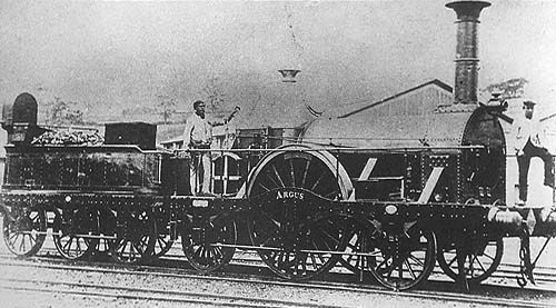
Knowing the subject before deciding what to model can be a big help. A lot of BG locos look impossibly daunting to build. Would you want to build this if you're not a very experienced modeller?
However, this could be a nice introduction to scratchbuilding. You could probably get away with using a simple OO gauge RTR chassis, like Hornby, with wheels refitted onto longer axles, and some added frames and spacers to keep the wheels in place. Or a OO gauge chassis kit with wider frame spacers. Maybe not the most finescale result, but perhaps a lot easier than many "narrow gauge" locos:

Or this, perhaps from a OO gauge kit, again with modified Hornby or kit chassis. A Silhouette cutter should make the curvy splashers/footplate fairly straightforward. I have a cunning plan involving a Hornby 2721 Pannier:

The first loco, and similar classes, were in widespread use in the earlier years of the BG. The second was a small class and unusual in not being saddle tanks. Their time period and areas of use were quite limited. The third is only suitable for the final few years of the BG. I've thought of Miles as being a good project for a micro layout based on the type of location it may have run in, where it may be the only loco. It's strongly recommended to use P4/S7 standards, to get wheels to fit in the small and very visible splashers, but Miles could be built to any wheel standards.
Read books, search the web, study the BGS Data Sheets etc. There's a lot of information around (although still huge amounts missing). Find a little niche time or location where photos show things you think you could make reasonable models of, and have a go, to whatever standards you're capable of. You could even start off with a freelance Hornby Pugbash!
-
4
-
-
1:148 (UK N) on Scale 3 (14.2mm) gauge track ?
Recommendations are in the Data Sheets
. -
Why would anyone with an interest in the broad gauge not want to be a member? It's only £15 a year. Members get lots of really useful stuff in the Data Sheets, Broadsheet and other publications.
-
Thinking about it overnight, I have a feeling the top profile whilst nicely curved in two planes is a bit mimsy and worse still I suspect you will be able to see the top edge of the sky. A definite no-no...!
I wondered about that when I saw the photos. Surely you need more depth to hide the lighting. Have you tried lights yet? A suggestion in the book is to have the lighting set a few inches in front of the baseboard, so you don't get a poorly lit area along the front.
Not having a dig at you, or anyone else, but I wonder how many people have really read and absorbed the book before starting their layout. To me, a lot of the entries appear to be conventional layouts, where "Cameo" features are being added later. I'm trying to design mine starting with the eye level baseboard, proscenium arch and all the other relevant features, and then seeing how my vision for the layout can be created inside that. Of course my layout hasn't been started yet, while other people are well advanced with theirs, so maybe it's me doing it wrong
.


Welcome to the cameo competition
in Creating Cameo Layouts - The Challenge
Posted
I'll try to get a rough proscenium arch knocked up later, and see how it works.
I got a bit carried away looking up the proportions of people, the normal ratios of head size to total height, and the position of the eyes in the head. Not sure it it will help, but it's kind of interesting!