Jump to content
 
  • entries
    12
  • comments
    43
  • views
    6,550

850 Part 1


garethashenden

660 views

One can never have too many projects on the go at once. So lets start a third locomotive, before finishing the other two. This may sound like the worst idea ever, but there is actually some logic behind it. The second locomotive is Duncan's Buffalo. This should be a straightforward job of reassembling the chassis, I'm just not in the mood today. The first locomotive is my 517. The next thing to do on that is to build the chassis. This is starting to sound like a familiar stopping point, but there are other factors involved. Having built a replacement 2mm chassis for a Graham Farish Jinty last autumn I have become quite a fan of split chassis. I have decided I wanted to build my EM locomotives with split chassis from here on. The other thing I have been wanting to try out is CSB suspension. The combination of theses two new techniques led me to believe that a 0-4-2 was not the wheel arrangement to practice on.


Enter the 850 Pannier Tank. I mentioned in a previous post that as a poor student complete kits were beyond my reach. This is still the case and this kit, while now complete, is no exception. This was an affordable ebay purchase in that there were a few bits missing and the bidding didn't go too high. The chassis and wheels were missing along with, as it turned out, the footplate. All the castings were present and untouched. I was undeterred by missing bits, I figured that the wheels would be available from Alan Gibson and they do milled frames for an 850 so no problem. Upon receiving the kit I looked trough it and found that the footplate was also missing. Damn.


An email followed by a phone call to Alan Gibson resulted in wheels, crankpins, and a complete set of etches arriving through my door just before exams began. Everything was placed carefully in the box to await my freedom. At a rather excellent RailEx over the weekend I visited High Level and left the stand with a rather empty bank account but a bag full of goodies. These included three gearboxes, lots of hornblocks, CSB tags, and his CSB jig.


The first step is to determine the correct position of the fulcrums for the springy beam. This is where a lot of people give up as there is some fairly complicated maths involved. Luckily, someone has already done the maths and all that's actually needed is to plug the numbers into an Excel spreadsheet. First the axle loads need to be determined. Ideally these should be even and I see no reason why they won't at lest be close to even on this locomotive. The sprung weight needs to be determined, so everything except the wheels, motor and gearbox was dumped on a scale. This does include the etches that will be discarded but it doesn't include any extra weight I may add, so it's close enough. The total weight was divided by the number of axles to give the axle weight. This was entered into the Excel followed by the wheelbase in mm. After that a blind stab at fulcrum points was taken. The final input is the wire used as a spring. The default happens to be the same steel wire I have been using for Alex Jackson couplings, so I left it alone.


The spreadsheet provides figures for the maximum deflection of each axle. The actual deflection doesn't really matter but was does matter is that all of them are even. The positions of the fulcrums are adjusted until all three deflections are even. The High Level jig is marked out in 0.5mm increments, so I left it at that rather than balancing it perfectly but being unable to actually produce it.


On to actual building!

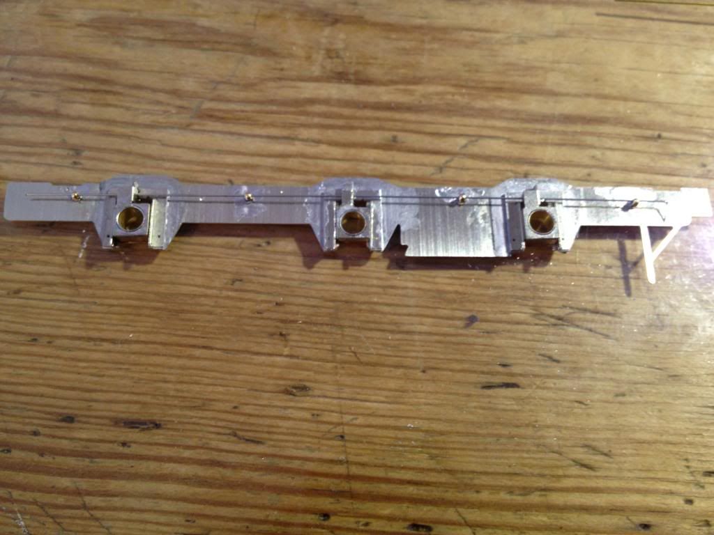
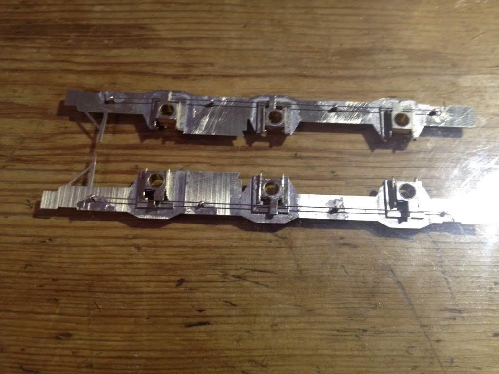
The frames were released from their etch and offered to the CSB jig. The jig is quite simple in design and use. Two round bearings are used at a time, one in the centre of the jig and the other in an adjacent axle. Small holes were drilled for the fulcrums which, with the jig removed were enlarged to the correct size. I am using Alan Gibson short handrail knobs as fulcrums. Everything has gone together quite easily, mostly due to the brilliance of High Level's designs. I determined that the middle axle will be the easiest to drive, the rear would interfere with the cab too much. So Spacesaver hornblocks were fitted to the middle axle with standard hornblocks at both ends. Unfortunately It was at this point I realized that I hadn't taken any pictures yet. So there is one of the first frame and one of the two together.

IMG_5385_zps4d1382fe.jpg

IMG_5387_zpsb23419ff.jpg

That's it for now. I'll put it together in the next few days.

  • Like 5

9 Comments


Recommended Comments

Excellent. It's always refreshing when someone intuitively 'gets' CSBs and takes to them like a duck to water.

Link to comment

Excellent. It's always refreshing when someone intuitively 'gets' CSBs and takes to them like a duck to water.

Thanks!

I can see why some people are put off but it's pretty straight forward.

Link to comment

Good start! If you can handle the spreadsheet and drill holes in the right place, the High Level jig and components do make the job very easy. I get the impression that some folk are phased by the need to estimate the final unsprung weight before building, without realising that you have the option of adding weight or changing the wire size once it is finished.


...I determined that the middle axle will be the easiest to drive, the rear would interfere with the cab too much...


What motor and gearbox do you intend to use? I've both pannier and saddle tank versions in only a slightly more advanced stage than yours and haven't made a final decision, but I reckon a High Level RoadRunner+, LoadHauler Compact+, or a SlimLiner+, each with the appropriate longer DriveStretcher would enable either the centre or rear axle to be driven without any interference with the cab.


...The postilions of the fulcrums...

I didn't know one was needed :scratchhead: You must have an interesting spellchecker...


Nick

Link to comment

Good start! If you can handle the spreadsheet and drill holes in the right place, the High Level jig and components do make the job very easy. I get the impression that some folk are phased by the need to estimate the final unsprung weight before building, without realising that you have the option of adding weight or changing the wire size once it is finished.


What motor and gearbox do you intend to use? I've both pannier and saddle tank versions in only a slightly more advanced stage than yours and haven't made a final decision, but I reckon a High Level RoadRunner+, LoadHauler Compact+, or a SlimLiner+, each with the appropriate longer DriveStretcher would enable either the centre or rear axle to be driven without any interference with the cab.


I didn't know one was needed :scratchhead: You must have an interesting spellchecker...


Nick

Thanks for that, I've never been able to spell.


It is a RoadRunner+ I think it will protrude slightly in front of the firebox but I should be able to hide it. I will also form the underside of the boiler from sheet and attach it to the gearbox so that the chassis is still removable.

Link to comment
  • RMweb Gold

Hi Gareth. A lovely selection of locos you've got on the go. Are you aiming for any particular member of the 850 class?

Link to comment

Hi Gareth. A lovely selection of locos you've got on the go. Are you aiming for any particular member of the 850 class?

Yes! I do. 1907. That has the features I wanted to model ie. half cab, H-spoke wheels, and a pre-1914 conversion date. It was converted to a Pannier tank in March of 1911. Still looking for a pre-WW1 picture though.

Link to comment

I can see why some people are put off


In your view, how so? - "A fear of the unknown", or "I've never used a spreadsheet before", or "I'm not clear how the system works"?

Link to comment

Well for me, it was the need to accurately predict the finished weight of the model (until Gareth undertook the mammoth and thankless task of explaining hard sums to a historian aka beating it into me with a heavy object at the MRC a few weeks ago). 


However, I am tempted to give it a go (or stand behind Gareth looking over his shoulder while making enthusiastic, if uncomprehending noises of approval while he does it) as I have yet another Alan Gibson 1076 lurking in the 'to be built' drawer - only this one's a saddle tank. 


drduncan

Link to comment

Well for me, it was the need to accurately predict the finished weight of the model (until Gareth undertook the mammoth and thankless task of explaining hard sums to a historian aka beating it into me with a heavy object at the MRC a few weeks ago)...


Yes, as I said earlier, I reckon the weight issue is something that stumps a lot of people until they realise it doesn't have to be that accurate. All you need to do is estimate the minimum unsprung weight (i.e. without motor, gearbox, wheels and axles) as Gareth did above by weighing the components. I then add about 10% to 15% to allow for solder, paint and wiggle room. When it's built you can then add further weight to  make up to your estimated value with freedom to move the weight around until the CofG is in the right place. If you need to add much more weight, just go to the next size of wire as the fulcra will all be in the right place.


My first attempt at CSB was a Gibson Buffalo saddle tank. IIRC, I used an estimated weight of 210g but when finished, with added wight for balancing, it was only about 190g, yet it works fine. After all, 10% less weight only leads to 10% less static spring deflection and you really can't see the difference.


As to hard sums, they're only for those that like them. For everyone else, there's the spreadsheet.


Nick

Link to comment

Create an account or sign in to comment

You need to be a member in order to leave a comment

Create an account

Sign up for a new account in our community. It's easy!

Register a new account

Sign in

Already have an account? Sign in here.

Sign In Now
×
×
  • Create New...