
William Dean's Express Tank

Being somewhat of a back-water in railway history, the Witney branch via North Leigh became home to many unusual vehicles, rarely seen elsewhere. I have already shown the standard-gauge Tilt Wagon ('Hat Box') but a particular claim to fame for this line was that it became the 'stamping ground' for William Dean's experimental 4-2-4 express tank engine, shown below entering North Leigh station.

William Dean's experimental 4-2-4T No.9 at North Leigh
My first encounter with this locomotive was many years ago, through the pages of John Gibson's “GW Locomotive Design - A Critical Appreciation”, which portrayed it as such an embarrassing failure that all traces of it had to be expunged from the record, with an order going out that 'this thing never existed'.
If that were true, Dean would hardly have provided an article for 'The Engineer, Sept.24th 1886', with a detailed drawing of the unusual outside Stephenson valve gear. Dean explained that this arrangement was intended to get rid of the excessive cramping up of the valve gear, necessary when large cylinders have the valve chests placed between them.

Outside Valve Gear on Re-built GWR No.9 (from 'The Engineer')
In fact, Dean had arrived in office knowing that the Broad Gauge was nearing its end and a new type of locomotive would soon be needed, to replace the Gooch singles. Amongst the ideas to be tested was the possibility of using express tank engines, as designed successfully by Pearson, for the Bristol & Exeter railway. E L Ahrons, who arrived at Swindon in 1885, described the original configuration of the engine as having a 30' overall wheelbase, including two carrying bogies of wheelbases 7' 3" and 5' 6" respectively. He also stated that the length of the platform was 36' 5-5/8".
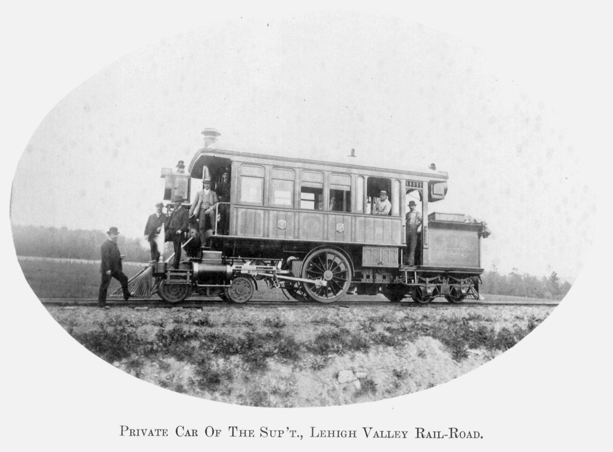
Very much later (around 1940), E W Twining produced an outline drawing, purporting to show the layout of the tank engine. A comparison of his sketch with the detailed drawing of the valve gear in 'The Engineer' reveals that it is simply not possible to fit this gear between the front bogie and the driving wheel, if the longer bogie is placed at the front! In my opinion, Twining's chassis seems to bear a very considerable resemblance to the Lehigh Valley inspection saloon, still in existence at that time, even down to the bicycle-style 'mudguards' over the front bogie wheels.
My own solution places the shorter bogie at the front and, with this configuration, a well-balanced design results. The front bogie fits neatly under the smokebox, leaving room for the outside valve gear, while the rear 7' 3" bogie fits immediately behind the firebox, within the overall 30' wheelbase. Apart from the reversed bogies, the dimensions conform to Ahrons' description.
The construction of my model followed similar lines to those I have described previously, when I built my 'Queen'-class engine. I built the engine in two parts: a rectangular chassis, carrying the driving wheels plus two bogies, and a box structure for the upper body. The boiler is represented by a half round section soldered into position between the two side tanks. The steps in my construction are shown below:

I have fitted an extended cab roof, similar to those used on other GWR tank engines in the same period, and a rear spectacle plate, appropriate for high-speed reverse running. Other features include cutaways in the tanks, to allow access to the motion, and tanks that extend a short distance in front of the smokebox, both as mentioned by Ahrons. The long (11' 6") boiler, in two rings, was designed to provide similar steaming capacity to the large-diameter boilers of the Gooch singles.
My model wears the new livery, introduced in 1881, with Indian red frames and vermilion lining (though at that time the wheels were still green). With this presentation, I believe that the engine is worthy of the description given by David Joy, when he visited Swindon around 1882 "I saw all about a mighty 'single' tank engine ... I saw drawings and all, and she looked a beauty".

My Interpretation of GWR 4-2-4T No.9
The real significance of this engine was that, while it showed that the 4-2-4 express tank engine concept was not appropriate for the standard gauge, it addressed an urgent need to re-visit valve-gear design for more powerful engines. The eventual outcome was, of course, the famous Dean Singles, with the same length of boiler and direct-driven valves, mounted below the cylinders. The family relationship can be seen in the following extremely rare photo of these two engines, side-by-side at North Leigh:

Dean 'Single' alongside its 4-2-4T pre-decessor at North Leigh
My model currently only has 'cosmetic' outside valve gear, cut from plasticard with my Silhouette cutter. It is powered by a Tenshodo WB28.7 SPUD, contained within the rear bogie, in the same way that my 4-2-2 uses a similar one in its front bogie. The model negotiates my small-radius curves with ease and does not share a tendency for de-railing, which apparently afflicted the prototype!
Update: I have created a 3D computer model of this engine - see https://www.rmweb.co.uk/blogs/entry/26347-william-dean’s-express-tank-revisited/
Mike
references:
Great Western Locomotive Design, John C Gibson 1984
The British Steam Railway Locomotive 1825 - 1925, E L Ahrons, 1927
Swindon Steam, L A Summers, 2013
Edited by MikeOxon
Restore images
-
 12
12
-
 1
1


18 Comments
Recommended Comments
Create an account or sign in to comment
You need to be a member in order to leave a comment
Create an account
Sign up for a new account in our community. It's easy!
Register a new accountSign in
Already have an account? Sign in here.
Sign In Now