Jump to content
 
  • entries
    134
  • comments
    483
  • views
    99,831

Moving to P4 (Post 3)


Knuckles

863 views

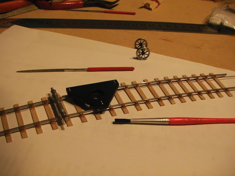
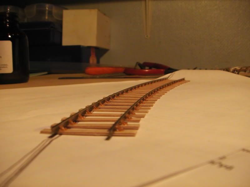
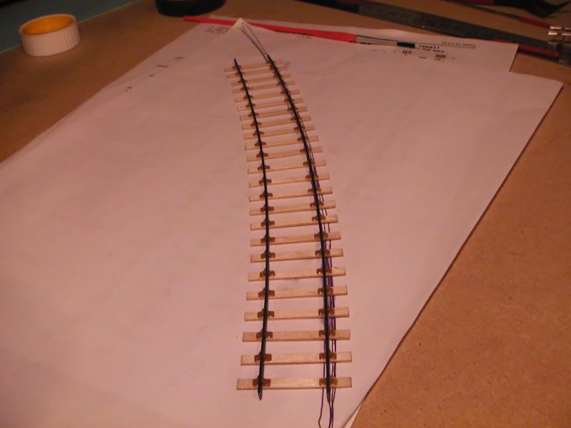
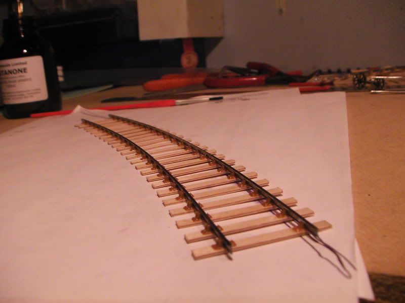
I started by applying Butanone glue to the bottom right chair and moved it along using the triangular gauge and the '+1' roller gauge, poking sleepers and chairs into place and gluing along the way, about 1/3 along I gauged and glued the far bottom left chair and then jumped a few at a time becasue the triangular gauge gauges a few at a time whilst widening slightly on the curve. As I was doing this I would move the roller gauge back every now and then to test the alignment, occassionally I got a tight spot but I pulled that out mostly, the gauge still went through but with a bit of tight friction.

I'm wandering if this is acceptable or not? It's still to gauge but not as brilliant yet I rekon it'll be ok.

I am not sure if the curve is a constant 4ft curve, neither am I sure if the whole curve should have had the gauge widening or not. My original plan wasn't a perfect curve but a pass of about 5 or so that were roughly the same, putting the finished curve to the rough plan seems ok so i think it's ok.

I have a question for anyone who might know; is it ok the 'gum up' the rail webs with butanone to lock the chairs in place to stop them skating about? It seems to work but I don't know if this is what you are supposed to do or let them slide freely for heat expansion. If this is acceptable what is the best thing to clean the rails with after? Seems like most of it evaporates though.

Warning to all; Ventilate your room and try to keep for face away from the work, Butanone has more of an, err.. 'effect' on me than most other things I've used. :P

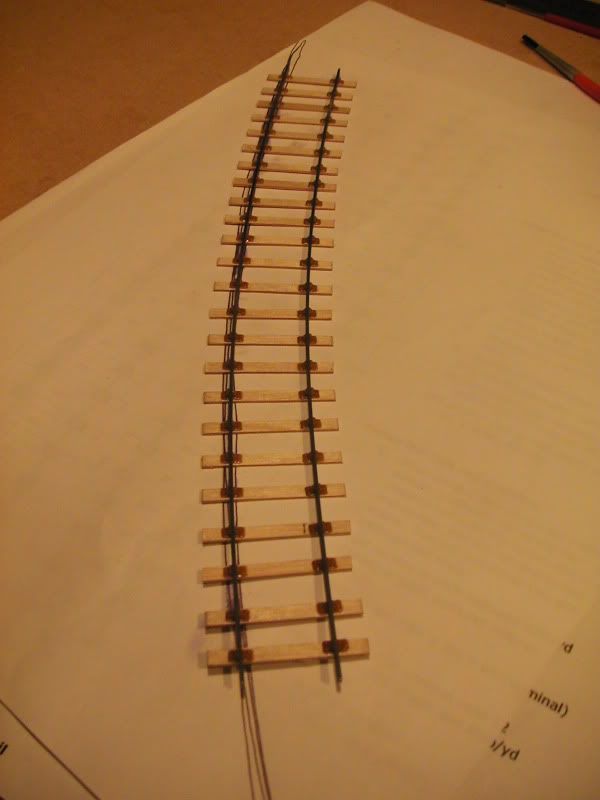
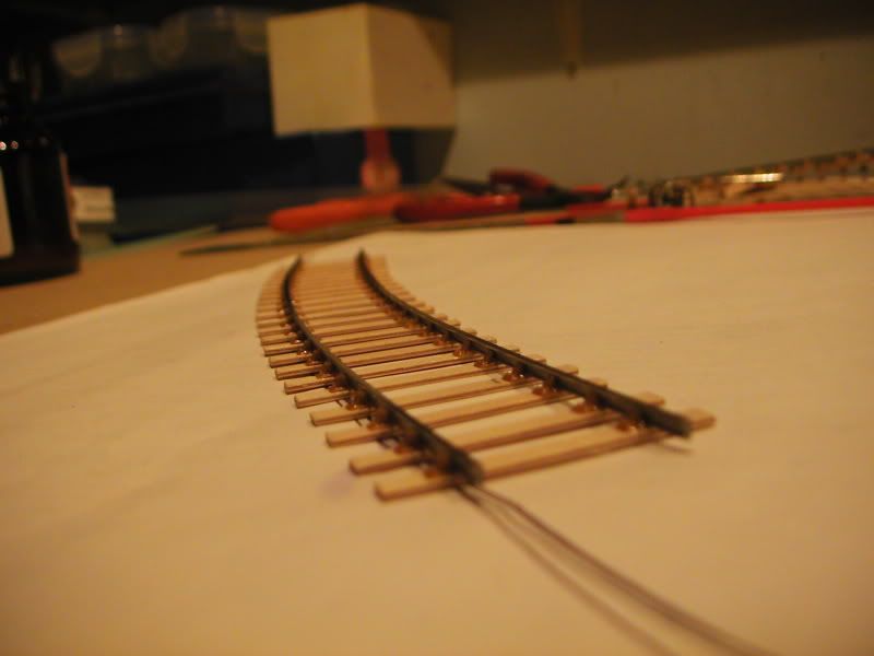
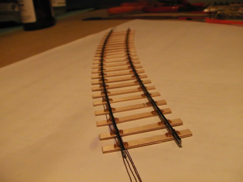
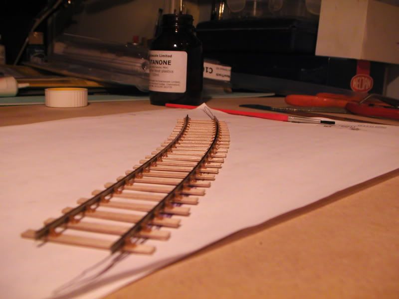
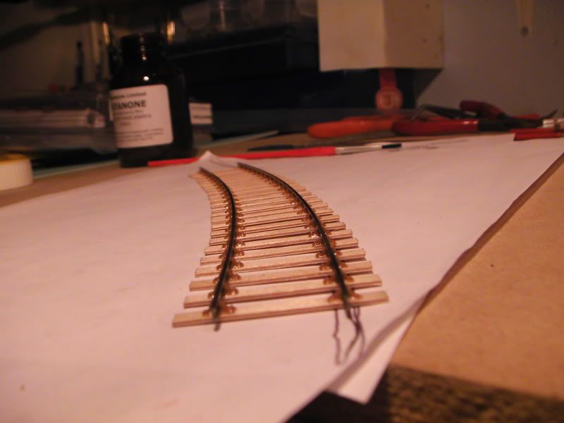
Finished pictures, curve flow seems constant and flowing.

Any advice? :)

Despite the things I'm unsure on, I 'think' this is a success at least.

Piccies:

PIC_2631.jpg

PIC_2635.jpg

PIC_2638.jpg

PIC_2640.jpg

PIC_2643.jpg

PIC_2649.jpg

PIC_2648.jpg

PIC_2645.jpg

PIC_2647.jpg

:) ?

  • Like 3

12 Comments


Recommended Comments

  • RMweb Gold

First of all, that's looking pretty neat to me, a nice smooth curve.


With regards to heat expansion, you'll find that the rails will do this of their own accord. I wouldn't worry about whether to 'secure' the rails to the actual chairs. The prototype isn't like that - there the rail is free to move slightly up and down, as the temperature varies. In essence, the model should be the same, so the trick is to leave some modest expansion gaps every so often. Exactly what kind of gaps, I'll let others decide, because I'm not aware of any laid-down principle, and I just make it up as I go along anyway, and despite some fairly warm exhibition halls, haven't had any major disasters.


In the worst cases, once you've painted the track, rail sides and chairs with your favourite weathering mix, the evidence of rail creep might present itself as tiny gaps in the paint, with the N/S rail showing through. If that happens, either ignore it, as it may revert when the temperature changes, or dab some more track colour type paint on.


The main thing is consistency with the gauge at this stage, and even here, some slight variation is not the end of the world. Don't worry too much about gauge widening - there are differing schools of thought here. Our DRAG test track has 4'+ radius curves, and we deliberately didn't bother with gauge widening when we laid the track (bog standard Exactoscale FastTrack for the most part). It's not a problem in reality when you come to run trains.

Link to comment

Top stuff, good gentle curve...does it fit where it needs to go or was this just an experiment to see how you got round corners? Impressive for a first time.


Mike

Link to comment

On thing to remember is that the chairs hold the rail at 20 degrees to the vertical. If the rail is pressed tight against the gauges then it can twist and become vertical, the upshot of which is that once the gauges are removed the rail springs back to 20 degrees and the track will be under gauge. Ideally the both rail head should just touch the gauges.

Link to comment

Here is the answer to finding your accurate curve...plotting.


Do you remember doing Math and wondering what use it would be?

Well now you know. You need this little formula.

y=A- √(A2-x2)


where A = your radius. & x is a point on the x axis. This will then give a point on the /-y axis.


Assuming that you don’t know what an x/y axis is...

Draw a line and mark off points along it at 10mm intervals.

This line is the x axis. Take the middle point and call this 0. This is called the origin.

Working out from the origin, at each 50mm point measure upwards (the y axis) in order the following and mark in mm.

Starting at 0;

0; 1,04; 4,17; 9,41; 16,78; 26,33; 38,10; 52,18; 68,63


Join up the dots and you have a 1200mm radius curve. This should give a curve 800mm long.

Normally you lay the track with the centre on the 1200mm radius.


If I run the figure again setting A at ± 10mm this will mark out the approximate position of the outside of the rail. i.e. where you can place dress making pins to locate the rail.

On the same x axis points and using the same axis line (the first few points are below the x line);


-10; -8,98; -5,86; -0,67; 6,64; 16,108; 27,78; 41,72; 58,03

10; 11,05; 14,21; 19,49; 26,93; 36,56; 48,44; 62,64; 79,24


Oh yes and measure your gauges, I struggled for years until I found that some of my gauges were not accurate.


Another thought is that you may still be thinking in terms of ‘setrack’ ie you get track lengths only in terms of curves and straights. What you would have between them is a transition curve. The EMGS manual has a whole section on this.

Link to comment

Thanks for your comments, guys. :)


I'll be honest the math's and algibra is a bit beyond me. I struggled to get my head around it at school and haven't bothered since, I also find the information in the P4 Digest Sheets confusing when it goes into the equasions. I do appreciate you taking the time to type it though, I just haven't a clue. :(


I do understand what you mean with the X & Y axis and plotting a curve by entereding in those variables, but not the equasion. I'm assuming the calculation gives the nubmbers you typed?


Also I didn't know the radius was supposed to be to the centerline of the track, so I guess this means my curve is slightly under radius. If that being the case, how would you go about curving and laying the first rail to be in accordance with a drawn centerline?


With the gauge springing back and just touching, does this mean the gauges should have an easy feel when being run up and down? Literally just scraping sides but no tightness, or is a little tightness ok sometimes?


I do have a question regarding C&L's flexitrack, and that is to ask if it is a tad under gauge? My gauges fit on it but rather tightly compaired to all the other track I built. I also noticed when you bend it the gauge doesn't widen so what are the opinions on this?


I'm a questionable guy today..arn't I!? :scratchhead:


??


I'm just new to this, much to learn. I've even brought a nice folder with plastic wallets for Digest Sheet and template print outs.


Oh yeah, to answer a question; I'm just doing various tests at the moment. I can't build a layout until I've finished renovating the loft but progress is slow. Next test is a wagon conversion (not sprung/compensated) and or a Exactoscale point kit.


Might try an Exactoscale curve first but unsure.

Link to comment

All progress is looking good. Butanone... ah yes, a new advantage I've found to this track building lark. I found that the more I used it, the better the results looked. One suggestion - I managed to stick (accidentally) a small piece of bluetack to the bottom of the bottle... didn;t notice it, but it stuck it lightly to my desk which was very useful when I knocked the bottle (again accidentally) and it didn't fall over. I think that Mikkel lost a bottle this was recently and it's best not to knock one over. I keep the bluetack on the bottle now.

I've also yet to play with an actual plan... built a turnout kit and now looking at various options for a photoplank (see Jim S-W's plank) as a good (simple - and I need simple!) start point. The S4 news has some good articles in it too - worth a browse, I presume you have a backlog if you recently joined. 169 has a nice little building a turnout kit article by Terry B... pseudo plank sized.

You're doing the right thing.

I'm off to the Watford show on saturday to stand and marvel at some finescale trackwork and work out what to do next - and maybe have a chat to Exacto - Len and browse all other stalls for ideas.

It's a new area of the hobby; I hope you enjoy it.

jon

Link to comment

On thing to remember is that the chairs hold the rail at 20 degrees to the vertical...

I assume that's a typo, Bill? If so, it's an oft-repeated one and is quite wrong. The rail should lean at a slope on 1 in 20 which is less than 3 degrees. 20 degrees would be a slope approaching 1 in 3. Yes, the plastic chairs are designed to provide this slope, but are your triangular gauges cut at this angle? Indeed, if you were to use roller gauges of the type with a groove around their circumference that grips the rail, by the time some butanone has been sloshed around, the chairs will soften and deform to hold the rails vertical.


Nick

Link to comment
  • RMweb Gold

Many thanks for sharing this Knuckles, following your entries and the helpful comments is extremely useful for us newcomers to this.


One suggestion - I managed to stick (accidentally) a small piece of bluetack to the bottom of the bottle... didn;t notice it, but it stuck it lightly to my desk which was very useful when I knocked the bottle (again accidentally) and it didn't fall over. I think that Mikkel lost a bottle this was recently and it's best not to knock one over.


Yes I've learnt the hard ward way to use the bluectack trick. Takes a little getting used to though: Having fixed the bottle with bluetack I came back later and wanted to move it: "Hm, why is it stuck to the table? - must pull hard to get it loose - oops!".

Link to comment

Hi, Knuckles,


Welcome to the wonderful (if sometimes frustrating) world of P4. Your sample length of track looks good and very neat - I hope you've got satisfaction and encouragement to progress from it.

That said, I'm a bit bemused as to what you are trying to achieve with a short length of curved track. If it's just a first stab at making some P4 track as a learning exercise, all well and good. If it's intended to form part of a larger project, such as a test track or part of a layout, I think you might run into problems when you come to join several sections together because, although the track looks quite smooth, it's unlikely to be exactly the same radius all along, especially with the way you constructed the curve template. To ensure smooth track on a layout, as already mentioned by someone on your previous entries, the plain curved track really needs to be built in situ or at least on templates created in situ - we're not making a P4 version of Settrack!. Plain track usually connects to point work, and since this is less adjustable for geometry, you need to fix the design and position of the points before you build the connecting plain track.

To draw the track plan, these days a computer ploting programme such as Templot seems to be the best solution. However, if you don't have access to it or know someone who has, the next best way is with paper templates (S4 Soc, C&L, P4 Track Co., etc). you can curve points to a degree by cut & pasting the template onto some backing paper. This also applies to curved plain track, although not essential - but it does help with sleeper placement.

The best manual method to set out a curve is by off-sets, as described above. If your not into formlae and calculations (its pretty straight forward with a calculator or computer) then you can draw fixed radius curves with the aid of string, as you did. However, rather than tie the pencil with the string and generate a wobbly curve, it would be better to just mark a series of dots a few inches apart and then join the dots using a flexible strip of wood or a steel rule stood on edge. These continuous materials tend to addopt a smooth curve when bent. Use pins, screws, etc to help hold in place whilst you draw along the curve.

You mention wanting to run Pacifics round your nominally 4 foot curve. If the locos have some side play on the centre axle and the bogie/truck sufficient throw, my experience is that it should be OK - but beware of unintended tighter radius sections/kinks in the main curve. Entry into your curves will look better, give smoother running and reduce the risk of bogie/truck wheels grinding on the backs of steps if you use transition curves. These are explained in the S4 Soc manual. Again, if you don't fancy calculating the off-sets, a rough alternative is to arrange the circular curve to "miss" touching the straight (or larger radius curve) by say 10 - 12 mm, then over a length of 400 - 500 mm (half each side of the tangent point - where the curve radius line meets the straight at right angles) blend the two lines using the flexible strip. Transitions really do make a huge difference.


Regards,


Dave.

Link to comment
I'm a bit bemused as to what you are trying to achieve with a short length of curved track. If it's just a first stab at making some P4 track as a learning exercise, all well and good


Yup. It literally is my first steps in P4 so I 'm just trying to be patient and do a little bit here and a little there to see what I'm capable of, make a few mistakes (such as sticking the keys on the wrong way around!) and take it from there really. I can't build a new layout yet because still sorting the loft out.


Thanks for your advice on the curves, the points linked with a bent bit of wood sounds like a great plan. I do have this new version of Templot but haven't sat down to try to understand it and crush my head yet.


Thankyou all for these detailed comments, it's really appreciated and encouraging. :)


I think I might equip my glue and flux bottles with sticky blue goo, seems a good idea. I've been lucky enough to not spill it all but it's probably only a matter of time.


Many thanks for sharing this Knuckles, following your entries and the helpful comments is extremely useful for us newcomers to this.


Hey, I'm a newcomer too! What you see in these posts is literally all I've done.


I can fully appreciate what you are saying though, I've spent a lot of hours doing the same thing to other people's P4 threads - still do actually. ;)

Link to comment

Hi Knuckles,

I do understand what you mean with the X & Y axis and plotting a curve by entereding in those variables, but not the equasion. I'm assuming the calculation gives the nubmbers you typed


Yes it does. I will do a blog entry sometime as to how this works and a simple way of how to work it out.

Like making your own track this can be quite satisfying. Templot is cheating...and also I don't have it.


Also I didn't know the radius was supposed to be to the centerline of the track, so I guess this means my curve is slightly under radius. If that being the case, how would you go about curving and laying the first rail to be in accordance with a drawn centerline?


Well this is how I understand it to be.

I would plot the position of the inner rail and pin it with dress pins. Then use the triangular jig to let the outer rail go where it wants.

As others have pointed out, flex track and the moulded chairs are at a slight camber so your jigs will be tight if you push them all the way home. These jigs were designed for Joe Brook-Smith type track where you had to solder each chair. The rail was of course held vertical then.

So when using the gauge I would only use it on the rail head. Otherwise there is a risk of the track narrowing.


I think that Dave Holt has raised the same issue that I have, with regard to thinking in terms of set track.

I used to do the same when I first started to make track (flexi-track wasn't available then) and quickly found that it was harder work than it needed to be. I now try to make track lengths as long as possible but making sure that the sleeper spacing is correct and use cosmetic chairs. I also score the top of the rail to simulate the joint.

Flexi-track is now a huge boon to those of use working in EM and P4, unfortunatly it does not have keyed chairs. And if you are really pedantic there is a lack of choice over bolt pattern. I would like to lay some inside keyed track one day.


The flexible peice of wood or nylon is great. Did I understand that you are physically bending the rail so that it is curved before building? If so I suggest that you could be creating some extra work for yourself.


I would make the track by fixing the chairs and sleepers onto one rail over the sleeper spacing drawing so you end up with a fish bone structure.


Then I would mark out the position of the inner rail using the co-ordinates above, that is (x/y)

(0,10), (50,11.05), (100,14.21), (150,19.49), (200,26.93), (250,36.56), (300,48,44), (350,62.64), (400,79.24)

putting pins into these points.

Then I would lay the straight fish-bone onto the board and gently push it into postion against the pins. Then pin the other side of the rail.

Then fix the outer rail as you have done before.

When it has set I would be happy to let it spring out a little when installing as you are only really concerned with a minimum radius..


Keep pushing on, we are all here to help you. I started doing this when I was at school. I had no idea what I was doing right or wrong and had no-one to ask. So I was struggling for years.


Andy


edit; corrected the co-ordinates to the correct format.

Link to comment
  • RMweb Gold

Hi Knuckles, you ask the question regarding whether your C&L track is a bit 'tight to gauge?'. Well, in my experience, I have also found this. We used quite a lot of it on our first test track in our Area Group (DRAG), and even on the straight bits we found that there were some places where it had gone a bit tight to gauge. As a result we have used Exactoscale FastTrack on our second test track. I wouldn't say never to use C&L flexitrack in P4 , but I would be 'aware of the experiences of others'.


Someone rightly mentioned the limitations in flexitrack in terms of the types of chair that you can use - basically the one that C&L have moulded on the flexitrack! However, this doesn't bother everyone, and I guess it depends on what your personal priorities are. I challenge anyone to tell the difference at 'normal viewing distances'. Or to put it another way, are we modelling for normal vision or the (sometimes) unforgiving macro lens on modern digital cameras?...

  • Like 1
Link to comment

Create an account or sign in to comment

You need to be a member in order to leave a comment

Create an account

Sign up for a new account in our community. It's easy!

Register a new account

Sign in

Already have an account? Sign in here.

Sign In Now
×
×
  • Create New...