


CF MRC
-
Posts
2,033 -
Joined
-
Last visited
Content Type
Profiles
Forums
Blogs
Gallery
Events
Exhibition Layout Details
Store
Posts posted by CF MRC
-
-
- Popular Post
- Popular Post
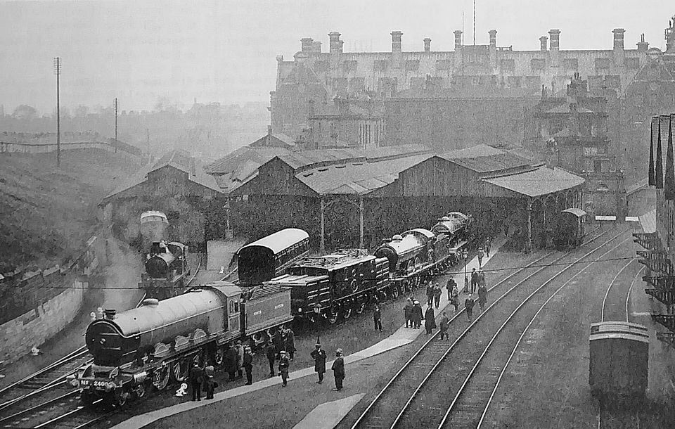
I thought on this doyen of ECML threads somebody ought to mention a famous centenary.

One has to do it. The loco in front is 2mm scale Royalty, having been superbly made by the late Denys Brownlee in 1987 and subsequently covering hundreds of miles on Copenhagen Fields.
Tim
-
 21
21
-
 2
2
-
 3
3
-
I think it will look odd without the boiler lined out, Ian.
Tim
-
 2
2
-
 1
1
-
-
Just turn up the amps until
something glows / smokes…
Tim
-
 1
1
-
 1
1
-
-
CF has always had its own bespoke front barriers made from Speedframe. They incorporate a low rail for children to stand on and take into account the strange shape of the layout. They take up a minimum amount of transport space (the vertical frames are permanently assembled) with the horizontal rails adding useful low ballast to an otherwise slightly unstable travelling case.
If you want see the layout without barriers then come to an MRC mini exhibition at Keen House or 2mm Scale Association event (as in HAMW, series 2, episode 3).
Tim
-
5
-
2
-
-
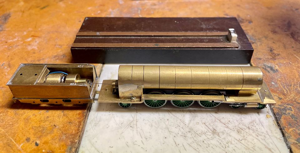
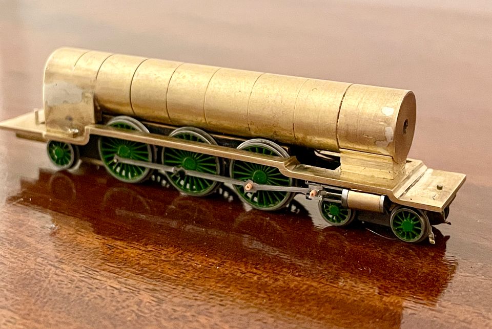
The Raven 4-6-2 class is now mechanically complete. It slightly ‘stuck its elbows out’ on the slide bars when running and so a restraining wire was soldered across the back of the crocodile, using 145 deg solder.
The driving wheels are lined out at the hub but the rims are not yet black.
Tim
-
12
-
5
-
-
- Popular Post
- Popular Post
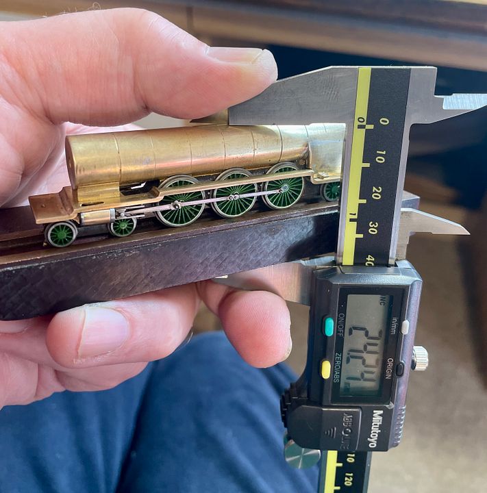
Measuring spot heights on locos / rolling stock can be achieved using surface plates and gauges / markers for model construction. My take on this is to use a piece of Tufnol with some PCB ‘rails’ set tight to gauge to locate a chassis very precisely (i.e. no side movement on the wheels). This block also has a coupling height gauge incorporated.
The way it is used is that a digital vernier is zeroed on the thickness of the block and ‘rails’. The block material needs to be of consistent thickness, but also quite hard and shiny to allow a vernier jaw to slide easily. The loco is positioned on the block, being held with one hand, and then the callipers used to make measurements or perhaps scribe a line for e.g. handrail stanchions.
The photo shows that the Skittle Alley boiler height is a fraction under, but should be about right when it gets a coat of paint…Tim
-
15
-
6
-
2
-
- Popular Post
- Popular Post
Sorry to be late on parade with this post but a few pages ago there was talk of using surface gauges / markers for model construction. My take on this is to use a piece of Tufnol with some PCB ‘rails’ set tight to gauge to locate a chassis very precisely (i.e. no side movement on the wheels). This block also has a coupling height gauge incorporated.
The way it is used is that a digital vernier is zeroed on the thickness of the block and ‘rails’. The block material needs to be of consistent thickness, but also quite hard and shiny to allow a vernier jaw to slide easily. The loco is positioned on the block, being held with one hand, and then the callipers used to make measurements or perhaps scribe a line for e.g. handrail stanchions.
The photo shows that the Skittle Alley boiler height is a fraction under, but should be about right when it gets a coat of paint…Tim
-
21
-
4
-
 1
1
-
4
-
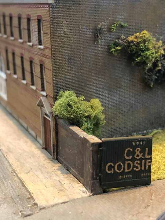
Styrene sheet brickwork can be made to (near) scale, as we have on CF.
This brickwork is made from heating 20thou styrene on a photo etched zinc plate and then pealing it off at the correct moment. It produces irregularities that can be used to good effect. It then comes down to how you paint it. The printing plate dates from the 1970s and was made by Dave Hammersley, AKA Roxey Mouldings.
Slaters brick sheets can also produce an effective result, but the bricks are poorly defined and rounded. The secret with this is to sand the surface down until the bricks effectively almost disappear. There are plenty of photos on the CF thread that show various techniques in use: getting the colour and corners right is 90% of the battle: the majority of buildings on CF don’t have any brick relief.
Tim
-
7
-
1
-
-
There are an overwhelming number of ‘how to’ videos on YouTube some of which can be very informative. The disappointing thing is when they take so long to show very little.
I think a series of staged photos can be just as informative and there is no doubt that camera phones have revolutionised this aspect of ‘how to’. It’s very tempting to just show what you’ve made at the end of a session, but the steps along the way will probably help people rather more - it’s what I try to do with my 2mm stuff on RMWeb .
Having taught at Missenden for many years, I would say that the ethos is to give people the confidence to get on with their modelling and to achieve finishes on components that they didn’t realise they could achieve. Tony & I also work on the Lazarus principle with some of the kit builds that are presented.
It’s also jolly good fun helping fellow modellers on their way…
Tim
-
15
-
2
-
-
I do like the way you have made a really tricky component (the tank fillers) simple by clever design.
Tim
-
8
-
1
-
-
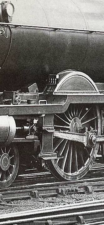
It would have to be NER livery Michael, as the picture is pre-grouping. The 4-6-2 class is in works grey, albeit the front buffer beam has already been trimmed back.
Tim
-
2
-
-
Are you referring to this yard, Richard?
On a different topic, is the layout DC or DCC Peter?
Tim
-
2
-
1
-
-
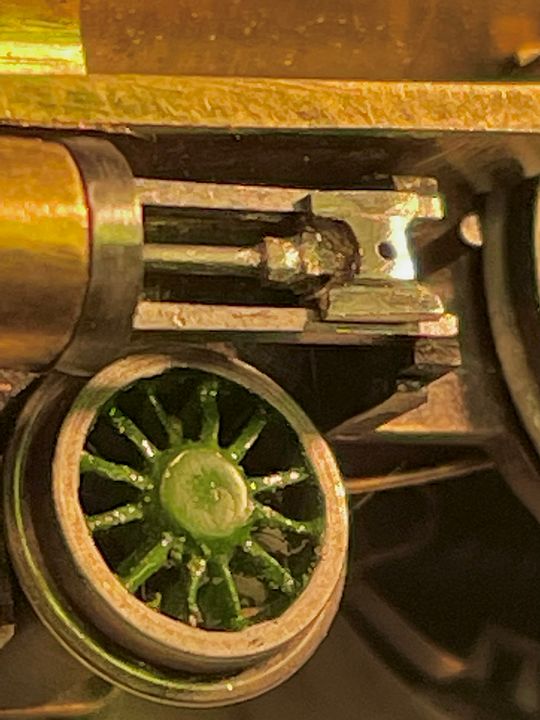
Little & LARGE. The driving wheels on the Raven 4-6-2 class have been lined out, just awaiting the black axle ends. Meanwhile, I have started to fettle the cast lamp brackets for my 3.5” gauge King Arthur, Sir Sagramore, in a scale approximately an order of magnitude bigger, i.e. 1/152 vs 1/16 full size.
Once the Skittle Alley is re-assembled I’ll probably work on the KA (see separate thread) for a while.
Tim-
15
-
-
I agree with Jerry. My Baldwin 2-6-0 has a slightly ‘loose gearbox’ as does Mons Meg. Engineering four bearings in line is too tricky.
Tim
-
1
-
-
Slightly going off topic, but I always use the 2mm scale ‘boot test’ for such calculations. Place a figure next to the ground texture and see if it would twist it’s ankle or trip up on it. It is especially useful for textures on e.g. roads. So many layouts are spoiled by using ‘grit’ as a texture in goods yards. In scale terms there virtually isn’t a texture and just plain emulsion paint with pumice filler is all that is needed.
Tim
-
3
-
6
-
-
- Popular Post
- Popular Post
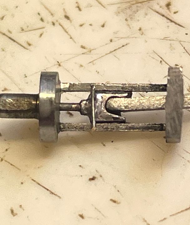
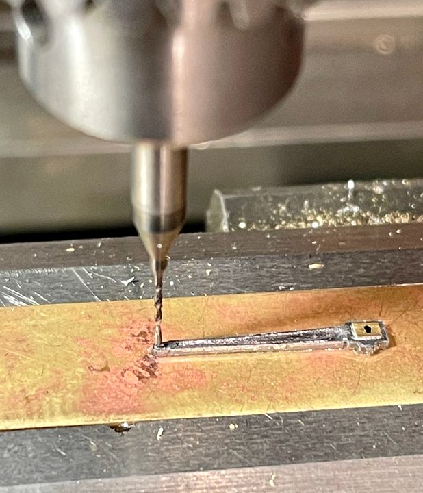
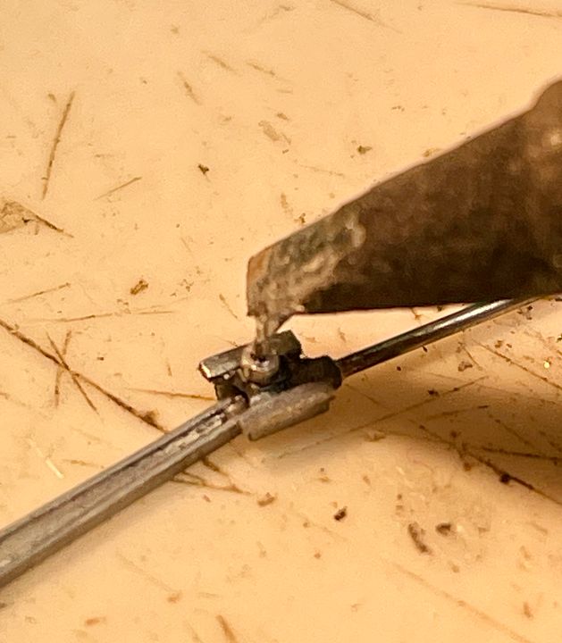
Holding your work whilst working on it is one of the biggest challenges in 2mm scale (and others). The simplest way is to glue the component to a bigger piece of metal to hold in the vice. The holding area can be flooded with a puddle of fast setting cyanoacrylate and then the rod dropped into place: the glue is then ‘set’ with some accelerator liquid. The photo below shows how I set up the con rods for re-drilling the big end holes in the brasses. The measured position from the little end was marked with a fine marker pen and then the table shifted on the axis using the dial from the little end reference point: the drill more or less landed on the spot (I erred on making it a touch shorter). Removal and clean up with a scalpel blade is straightforward.
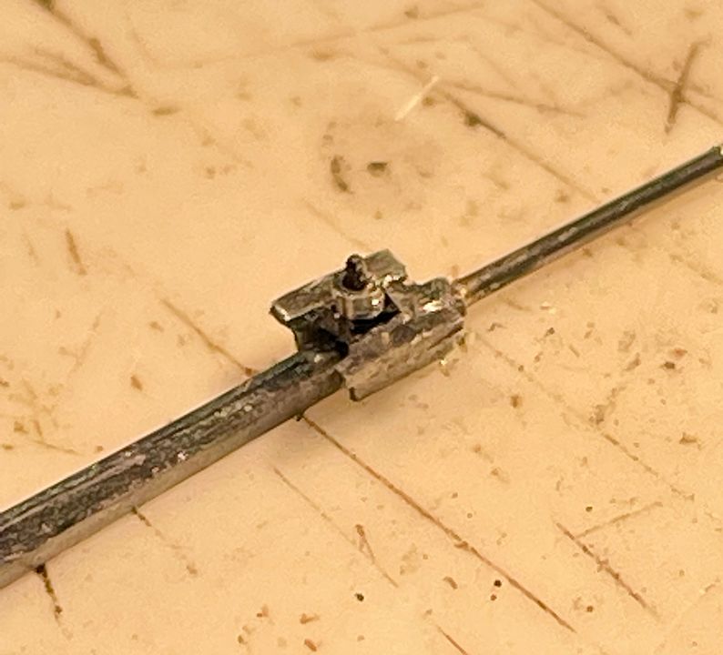
Once it all felt pretty free, the temporary plastic insulation collar was replaced with a steel version. The top of the cross head was coated with a black indelible marker pen, to act as an anti-flux. The steel collar was cut from a 0.4mm bore syringe needle.
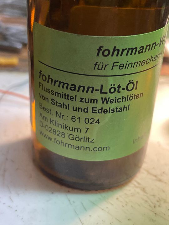
A minuscule amount of this German flux was applied to the tip. This flux is excellent for steel, it is a bit ‘oily’ and very corrosive.
The iron is brought into contact with the pin and flux with just a small amount 145 degree solder on the tip. It boils up the flux and the solder immediately flashes into the joint, at which point the iron is removed, of course. I have never got on with cigarette paper washers when assembling valve gear as they make the joints too sloppy.
The con rods are a very close fit to the slide bars at top and bottom of the crank throw, but they just kiss past, I don’t think the bars will need any adjustment. The big end will probably have a turned collar made for it.
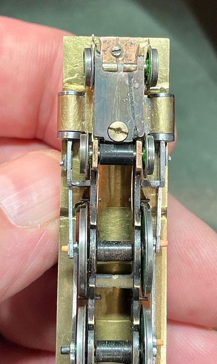
The alignment on the frames, wheels and valve gear is quite satisfactory, without any nasty bends anywhere: an advantage of working to a true scale / gauge.
The front steps will need to be robust and well fixed as they must not touch the connecting rod (at least on one side).Tim
-
10
-
2
-
20
-
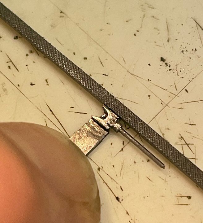
I recollected you doing it for Valour, Tony. I didn’t fancy sweating on a bass facing, bearing in mind that the nearby flanges of the rod are also soldered on. It didn’t take long to make the square hole with an escapement file and then trimming a block of brass to fit.
Tim
-
9
-
1
-
1
-
-
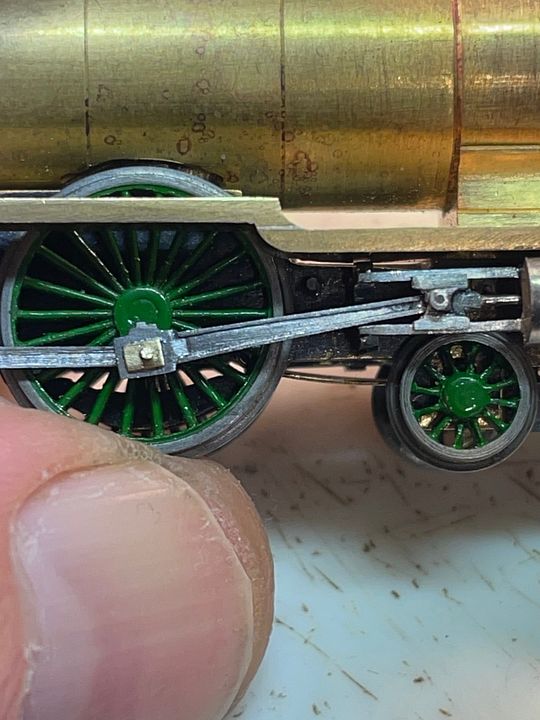
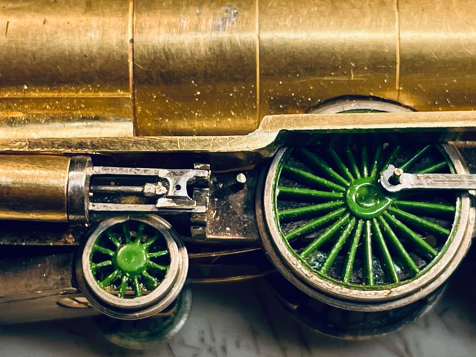
They are quite substantial cylinders and the class did have clearance issues, being cut down on the front buffer beam very early on in traffic and the rear valence necked in to give platform clearance.
Two things that puzzle me are whether the reversing gear balance weight (seen above the frames) was visible when the engine was in forward gear. Also, at some point, it seems that the wheels had some extra square-shaped weights added to the crescent shape as-cast. My engine will be in near original condition so I suspect it would not have the additions. Any ideas?
Thank you all for the kind comments - I try to show how it’s done in these posts, not just the end result.
Tim
-
4
-
-
- Popular Post
- Popular Post
Perhaps a bit crazy.
With such large big end bearings, it would have been churlish not to include separate brasses.
Tim
-
11
-
16
-
- Popular Post
- Popular Post
The Raven NER 4-6-2 class now has an ‘engine’ with the connecting rods roughed out and the cross heads and pistons in place. The connecting rods will require fluting, amongst other things.
Tim
-
16
-
8
-
- Popular Post
- Popular Post
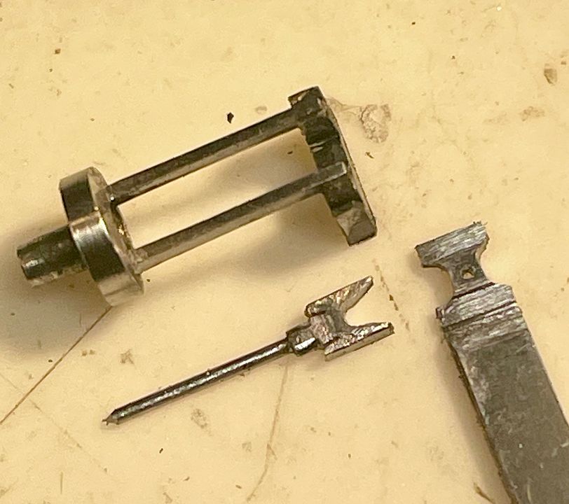
Making things from scratch is sometimes more straightforward than using components from a kit, as you can design the bits to be held whilst working on them. This was especially true when making the first cross head for the NER 4-6-2 class. The inner crocodile was filed up from 1mm steel sheet, drilled in the end for the piston rod (0.5mm pivot steel) which was silver soldered in place. It was adjusted to be an easy sliding fit in the slide bars with the piston originally being very long to give something to get hold of. The outer pivot and slide bar slippers were made from 0.5mm steel sheet, centred on the 0.4mm diameter pivot hole for the little end, but again with a long handle still attached.
Having the handle to hold enabled easier filing of the appropriate rebates and surface details.
The two components were soft soldered together and, once the main filing was complete, cut off from the handle.
The connecting rod will have a 0.4mm diameter pin silver soldered to its end which will be the little end pivot. This will be retained by a small collar on the outside of the cross head, representing the prototype little end retainer.
I now need to finish off the second cross head and then the connecting rods. I much prefer steel for valve gear, it is stronger and, being harder, is more forgiving when filing up components - it takes a little longer so you have time to think before you make a mistake - if you understand my strange logic.
Incredible what iPhones can do isn’t it?
Tim
-
19
-
1
-
14
-
We didn’t realise the name change until relatively recently Tony.
Tim
-
1
-
1
-
1
-
-
Tylor’s Tower became Ebonite in 1956, Tony. Interestingly, one of our group worked there in the early 80’s. It was demolished in 1983.
Tim
-
1
-
-
Interesting question re period on CF, Tony. We generally say, ‘between the wars’. However, my loco scratch building takes the period back to 1910. Of late I have settled around the grouping for loco building. Both Valour and the Skittle Alley would have rubbed shoulders at KX in the summer of 1923 - both in glorious pre-group livery - so that is enough of an excuse for me. I obviously also like the streamliners so that pushes the period to ‘37 onwards. Generally, so long as it’s apple green and teak and worth looking at by most viewers, I think, are not too upset.
The actual layout is again set ‘between the wars’. However the track plan near Gasworks Tunnel is up to 1932 and the presence of Belle Isle Up box sets it to the pre KX re-signalling. York Road tube also closed in 1932 so it is safe to say that end will be a time capsule of that era. I just have to make some horrendous underslung GNR somersault signal gantries to complete the scene…
The BR 2-6-2 you saw at Derby is 2mm scale royalty, being perhaps the most famous of the Groves locos. We never run BR stuff on CF, but you never say never, do you?
Tim
-
12
-
1
-


Wright writes.....
in Modelling musings & miscellany
Posted
https://www.maerklin.de/en/products/details/article/39968
Maybe our home grown products aren’t so bad after all.
Tim