


CF MRC
-
Posts
2,032 -
Joined
-
Last visited
Content Type
Profiles
Forums
Blogs
Gallery
Events
Exhibition Layout Details
Store
Posts posted by CF MRC
-
-
Any progress? I’m building a layout for them…
Tim
-
 4
4
-
-
I have published a textbook with Oxford University Press and their proof readers defend the use of the Oxford comma religiously. I dislike it.
Tim
-
5
-
 1
1
-
-
It could well be done that way, Nick, but I’m not sure how the spoke moulding is keyed into (or not) the metal rim. One could then use scale coupling rods and pins. The plastic that Sonic use is very ‘grippy’ -if you know what I mean- and quite tough.
Tim
-
1
-
-
- Popular Post
- Popular Post
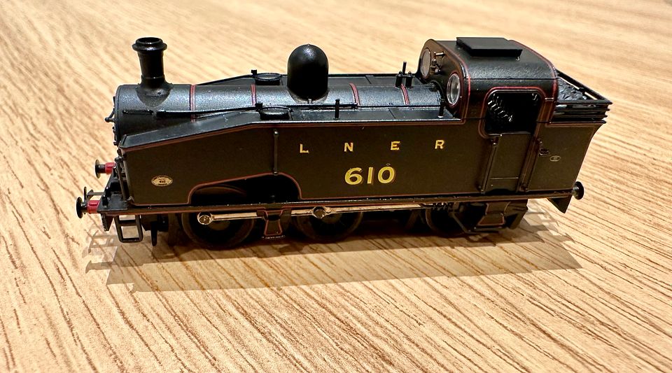
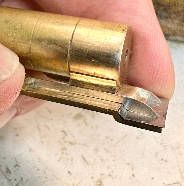
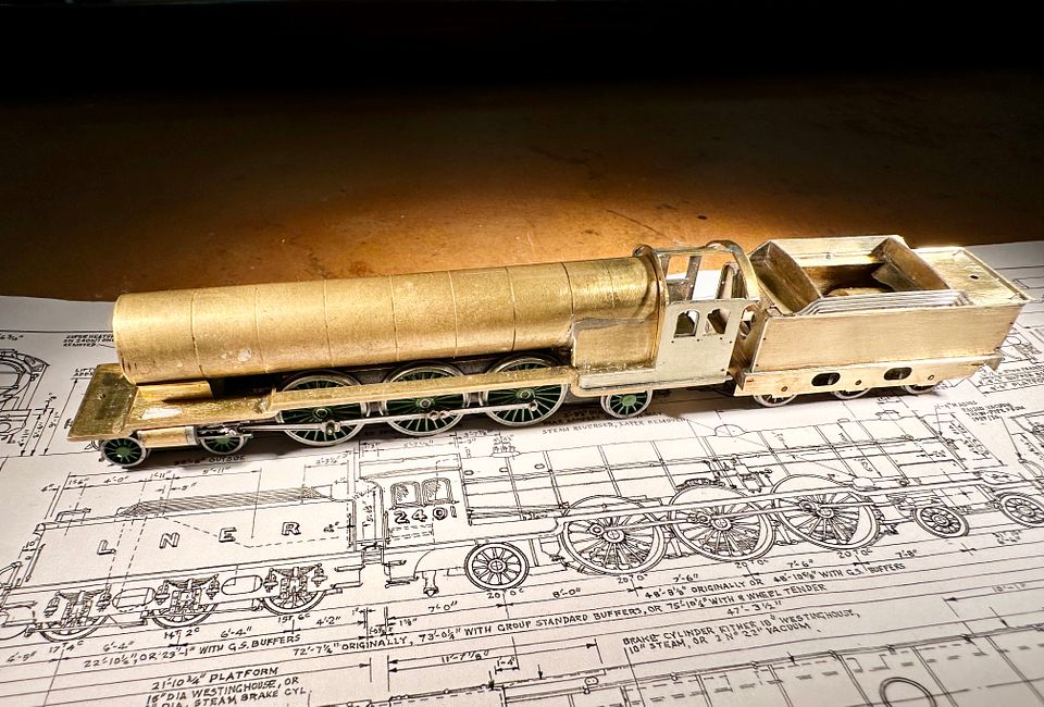
I have spent a very few hours on the easy conversion of the Sonic Models J50 to FS. This photo shows the end result which, quite frankly, is not greatly different to the original.

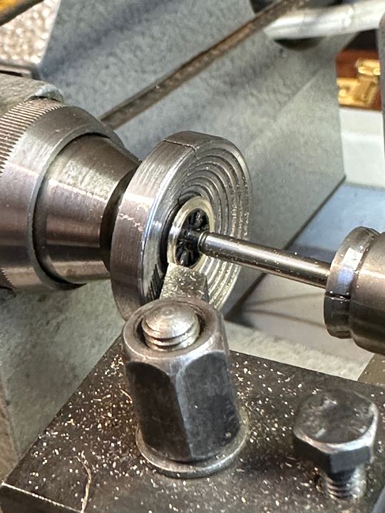
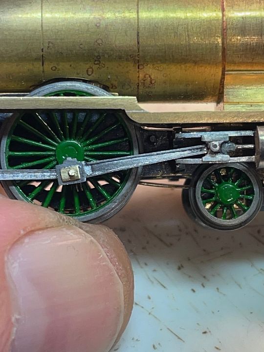
The wheel profile is very fine, as is often the way with modern N gauge. However the flanges, whilst not deep are too thick for FS standards. The individual wheels were mounted in a step collet and the backs of the flanges thinned down. The TC drill stub in the tailstock helped to make sure the wheel didn’t fly out by steadying it.
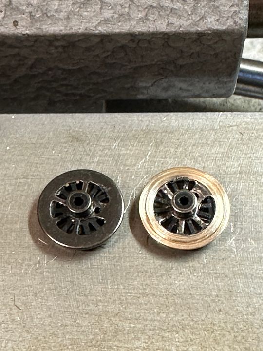
The reduction in flange thickness can be seen here. The wheels are interesting in that they consist of a brass casting for the rim and a few of the back spokes of the wheel and stub axle which is 3mm diameter and acts as the bearing surface running in phosphor bronze bearings. The front spokes of the wheel are plastic and bored 1.1mm for a plain steel axle.
The wheels were then mounted in a 3mm collet and a little bit removed from the front face to narrow the tread (I didn’t take a picture of this procedure). The wheels were then chemically blackened.
The wheels + 10-20 thou black styrene washer and then bearings were re-mounted on the axles at the wider FS back to back measurement and quartered by eye. The washers were to reduce some of the increased side play with an increased thickness needed on the back wheels where the steps and plumbing become rather close. Even so, these benefit from a bit of paring away with a sharp scalpel blade.
The coupling rods are simply held in place with tight fitting pins and are commendably thin. A few strokes with a file improved them further by removing the etch cusp and
thinning them down a little.
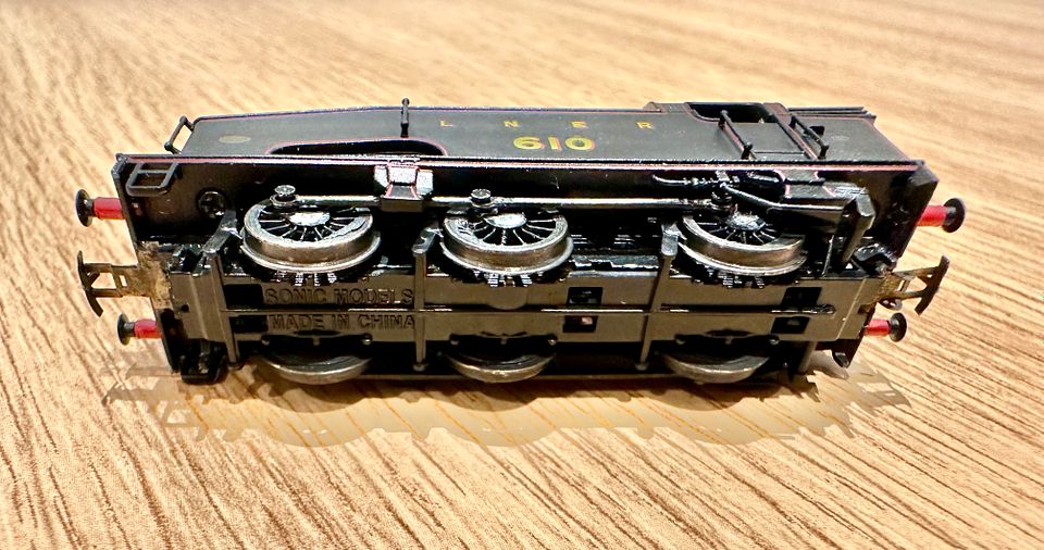
The end result is a very easily converted loco. All of the operations I have done could be undertaken with a simple lathe - even a mounted drill and sharp files - as there is no interference with wheel concentricity. The wheels are slightly chunkier than the fine scale standard but more than acceptable on a large layout like Copenhagen Fields. I am looking forward to more superb engines from this source!
Tim
-
15
-
 5
5
-
 6
6
-
 1
1
-
- Popular Post
- Popular Post
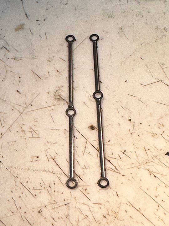
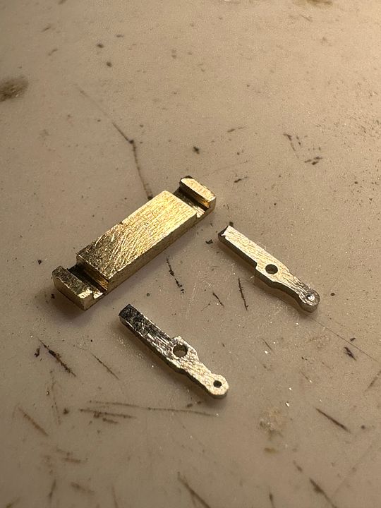
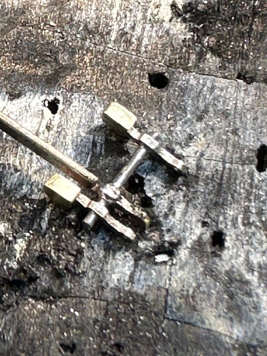
Over the last couple of days I’ve been making some of the between-the-frames parts for the Raven 4-6-2 class. These engines were fitted with steam reverse when new and a light-coloured plate was visible on the drivers’ (RH) side: this was the cover for a travel-limiting lever. On both sides, the balance weight on the weigh shaft was visible just in front of the splashers in full forward gear. All of this work will scarcely be visible, but might catch the eye when painted.
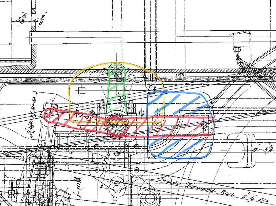
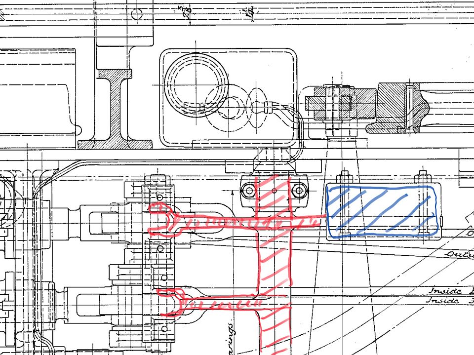
It took a while to work out the mechanism at the top end, but zooming in on the GA helped:
Blue balance weightRed lifting arm
Green limiter arm
Yellow backing plate.
Blue balance weight
Red lifting arms and weigh shaft.
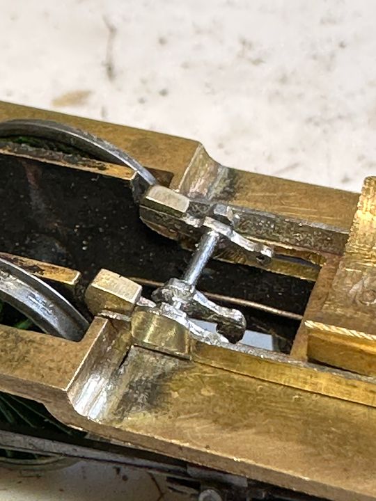
The lifting arms and balance weights were made as one piece, silver soldered together and then separated.
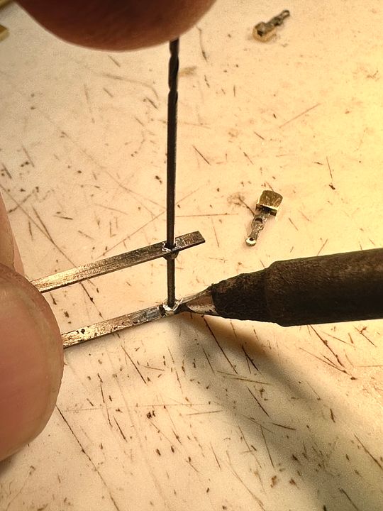
The trunnions that support the weigh shaft were reamed out 16BA nuts soft soldered to the inside of the frames. A hole was drilled on one side (where the cover plate is fixed) and that was used to align the nut on the other side, which was stabilised with a drill shank whilst soldering. These are much better than cocktail sticks as they don’t burn, fit precisely and will not take soft solder.
The cover plate was soldered on being made from a scrap of NS etch, but with a handle to hold it in place whilst soldering, it was also rebated on the back edge to aid location. The sacrificial handle was then twisted / cut off.
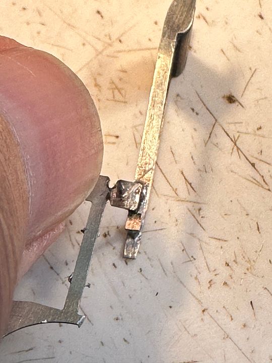
The lifting arm for the inside cylinder valve gear was made from NS CG rail and notched so that it could be clipped into place.
Soldering it onto the shaft was aided by burying the lift link into a charcoal block to hold it whilst the tinned components were quickly heated with a hot iron and plenty of flux. The long handle was subsequently removed by twisting it off.
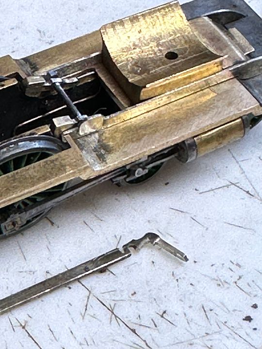
The whole assembly really doesn’t show up that much, but will when painted - probably vermillion for the shaft and weights.
The question, is, what was the colour of the limiter backing plate?
I suspect at least vermillion. What colour were NER engines between the frames? Answers on a postcard…
Tim
.
-
15
-
1
-
7
-
1
-
On 19/09/2023 at 11:31, Nig H said:
Tim Watson used these pens to line the CF Oerlikon stock, I think.
Here are some pics.
Nigel Hunt
I did indeed Nigel. The secret is with the dense yellow ink. It was straightforward to use and not too obtrusive. I think the problem with many commercial transfer systems is that the lining colours have too much value & saturation.
On my Midland engines the lining was applied directly using a ruling pen for the heavy yellow lines (Craftmaster straw) and then the black applied with Indian ink to thin down the straw to nearer scale thickness. My eyes were 45 years younger, of course…
Tim
-
2
-
-
It’s always fun to exhibit a layout close to the location it portrays. The personal touch, reminisces and feedback makes for a great time.
Tim
-
2
-
 1
1
-
-
- Popular Post
- Popular Post
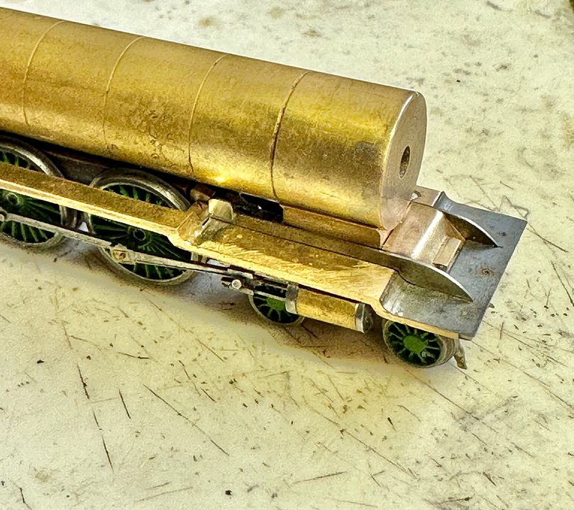
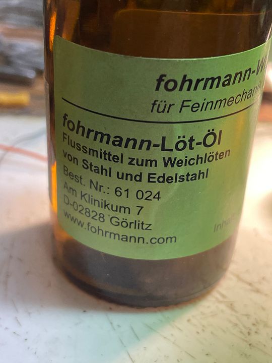
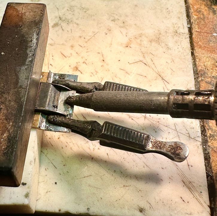
Not much to show with this post, but the front running plate has now been soldered to the brass core. As before, I used chemical blacking to ensure that the frames and piano front do not become irretrievably fixed in place. The front body fixing screw was also blacked and screwed into place to prevent the thread from filling with solder. The individual components were tinned with solder, the steel fluxed using a special steel flux which I sourced from Germany.
The components were held in place using ceramic blocks and miniature towel clips whilst the ERSA soldering station was cranked up to 450 deg C and applied to the steel plate with plenty of flux.
The flux is quite acidic and so after soldering the whole assembly was boiled in a saucepan of water for five minutes (don’t do this if you have white metal or low melting point solder!).
Next job will be the second running plate and reversing mechanism.
Tim
-
16
-
8
-
3
-
Thanks for posting that, I remember it being filmed. At the end I said it was 20 years from starting so that makes it 2004ish. That would also tally with the incomplete trackwork in the Belle Isle trough. All a bit younger then too!
Tim
-
5
-
-
On 22/08/2023 at 11:04, queensquare said:
7mm on the other hand, is much better in a small space as the intimacy suits the very high level of detail possible.
Jerry
I recollect quite a few years ago there was a massive 7mm gauge model of Millers Dale & Monsal Dale on display at Matlock. The modelling was superb, but it didn’t really ‘work’ for me as you couldn’t get far enough away from it to take in the whole scene. That being so, why not make it in a smaller scale?
Pendon’s Vale scene works well but could easily have used more perspective effects in the space available. CF is really just a big impressionistic painting with depth.
Tim
-
3
-
 1
1
-
-
I am a firm believer in large 2mm scale layouts…
Tim
-
8
-
1
-
-
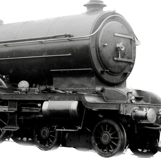
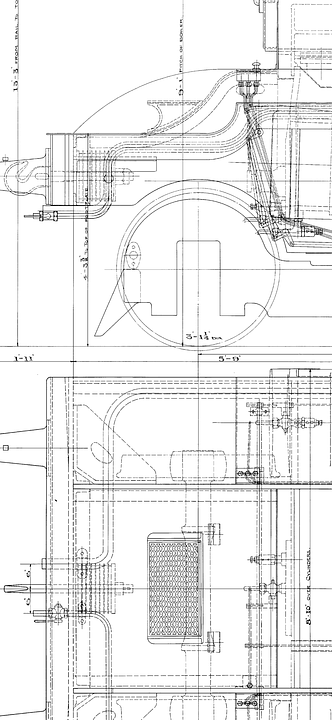
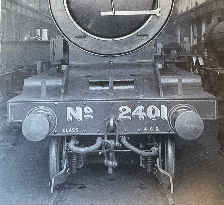
Thanks for the photos, Simon. This is the drawing for the 4-6-2 class.
Maybe we need some etched chequer plate, but then maybe not…
Tim
-
5
-
-
- Popular Post
- Popular Post
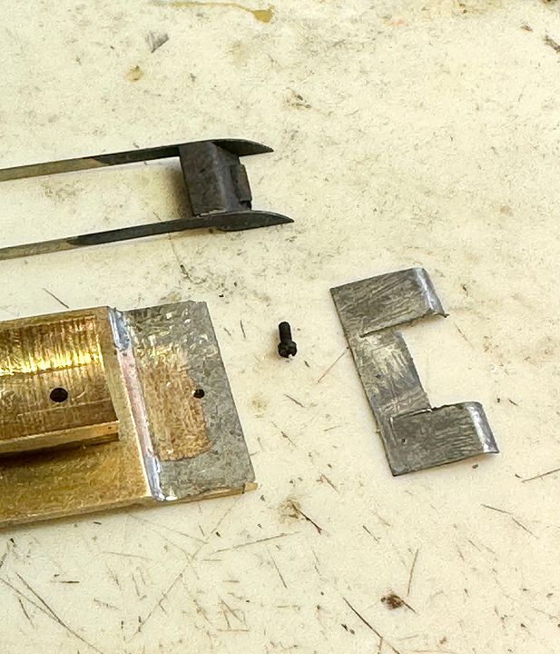
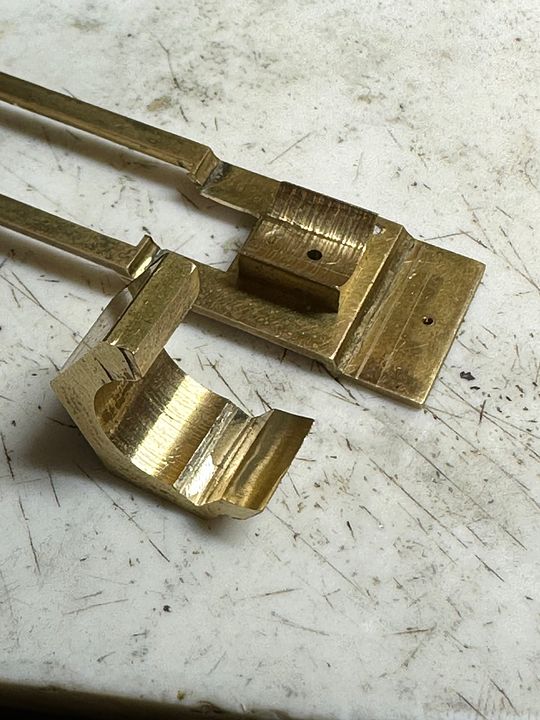
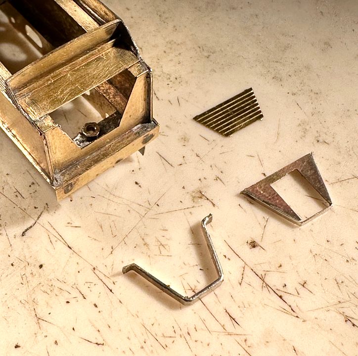
The Skittle Alley now has the beginning of an elegant front end with the frames, running plate, piano front and smokebox step made. The frames and piano front are removable, to aid painting and lining in the quite complex NER livery.
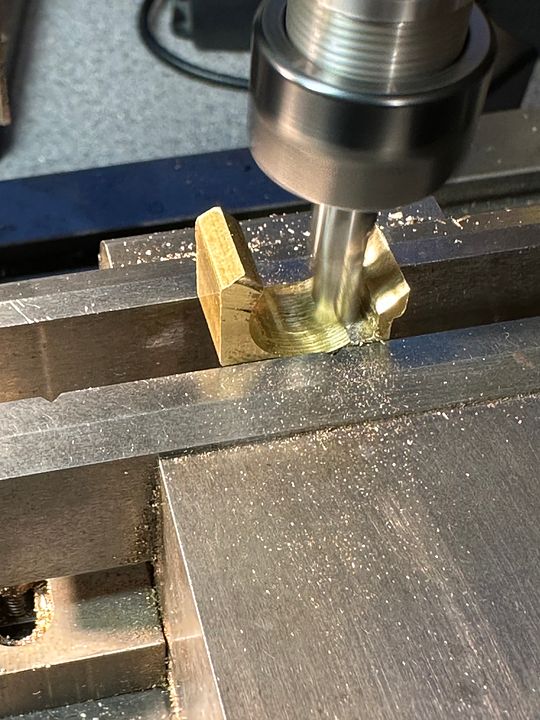
The prototype is very simple design, but has a tricky front step.
The piano front was milled from the same piece of brass used for the smokebox saddle.
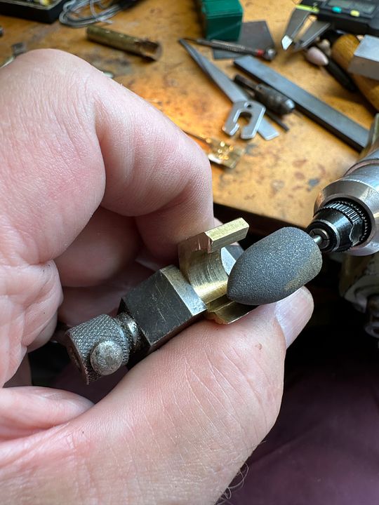
The curved front was carved in using pink stones and a large abrasive rubber polishing point.
It was then cut off and rebated on the underside to fit the running plate.
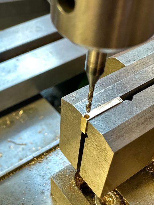
Meanwhile, the tricky little front step has a 6” diameter curved support and so this was made by drilling a 4mm-deep x 1mm diameter hole in some brass.
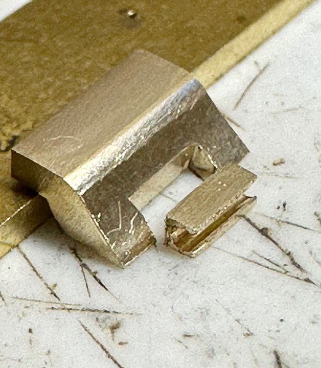
This was cut out, squared up and made to fit a recess cut into the piano front.
The two components were silver soldered together, taking care to heat up initially the large component from behind (silver solder saves problems with subsequent heating).
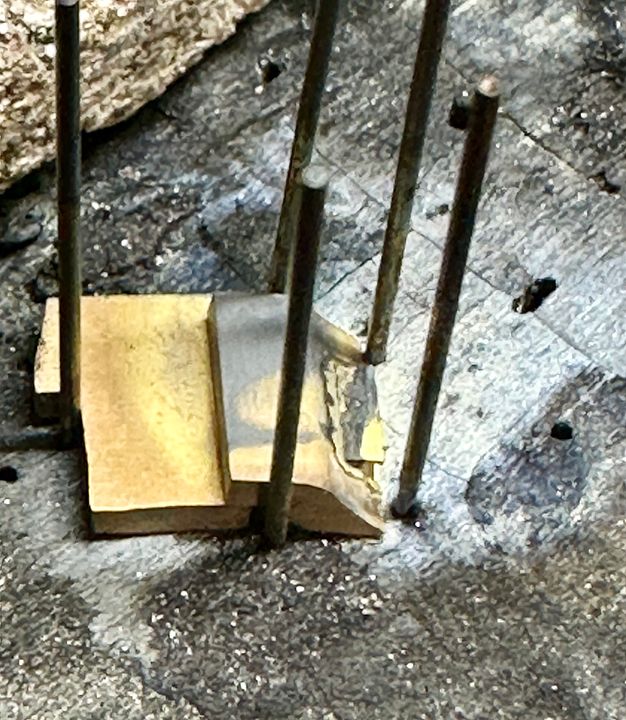
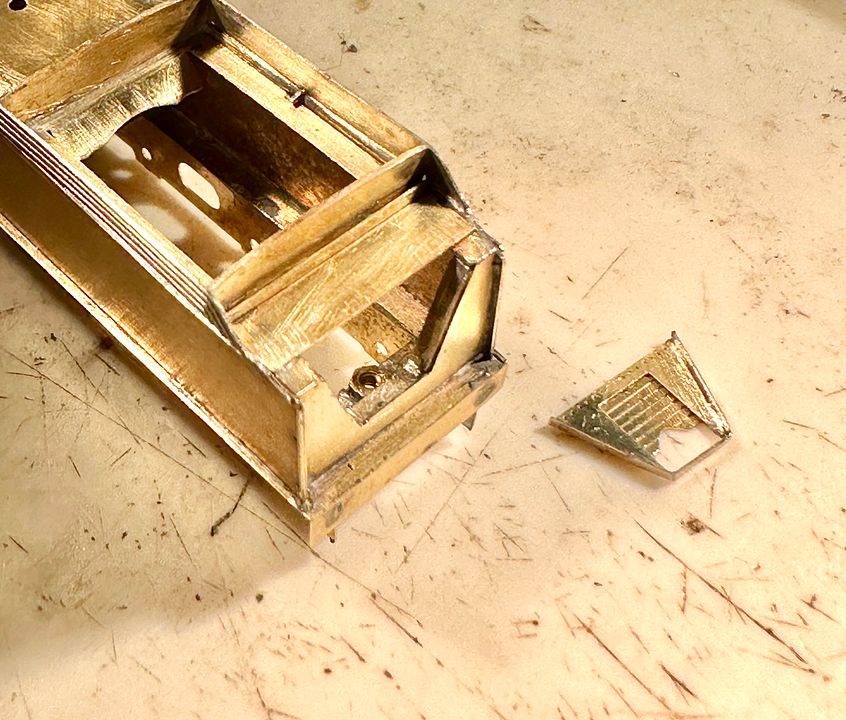
The frames were cut out from nickel silver, sweated together and then separated: there were no lifting holes in these engines when first built. The front running plate is a separate piece of steel. Why steel? It chemically black very well.
The assembly for holding everything in the correct place, whilst soft soldering the frames to the piano front, was quite tricky. The frames were pushed against the rebate previously formed in the smokebox saddle by means of a toolmakers clamp. The small front end clamp is an orthodontic device for expanding growing palates. Black marker pen anti-flux prevented bits being soldered where they shouldn’t, as can be seen. The sides to be joined were tinned and also the top of the piano box, so that the soldering iron tip had some solder to help transfer heat - a ‘dry’ iron is quite inefficient. With plenty of liquid flux and the iron cranked up to 450 deg C, the joint was soon made!
Painting and lining the frames will be a good deal easier with them dismountable.
The separate running plate will eventually be soft soldered on to the brass base; previous use of silver soldering makes this all together more straightforward. The running plate is awaiting holes for the lamp irons.
Quite a picture-heavy long post this one, but it starts to make the engine look a bit more elegant.Tim
-
17
-
19
-
5
-
On 11/08/2023 at 11:11, The Stationmaster said:
Having disgraced myself m by managing to have to stop for a blow-up while wielding the shovel (as an invitee) on one on the MHR many years ago I think I might be looking at a bête noire pour moi.
My father used to guard Ampthill Tunnel on the Midland mainline, during the war (he was in the home guard). He told me that the American engines used to have to stop to make steam before continuing south wards.
Tim
-
1
-
1
-
-
- Popular Post
- Popular Post
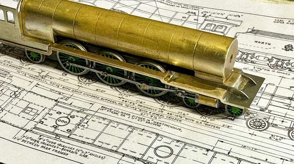
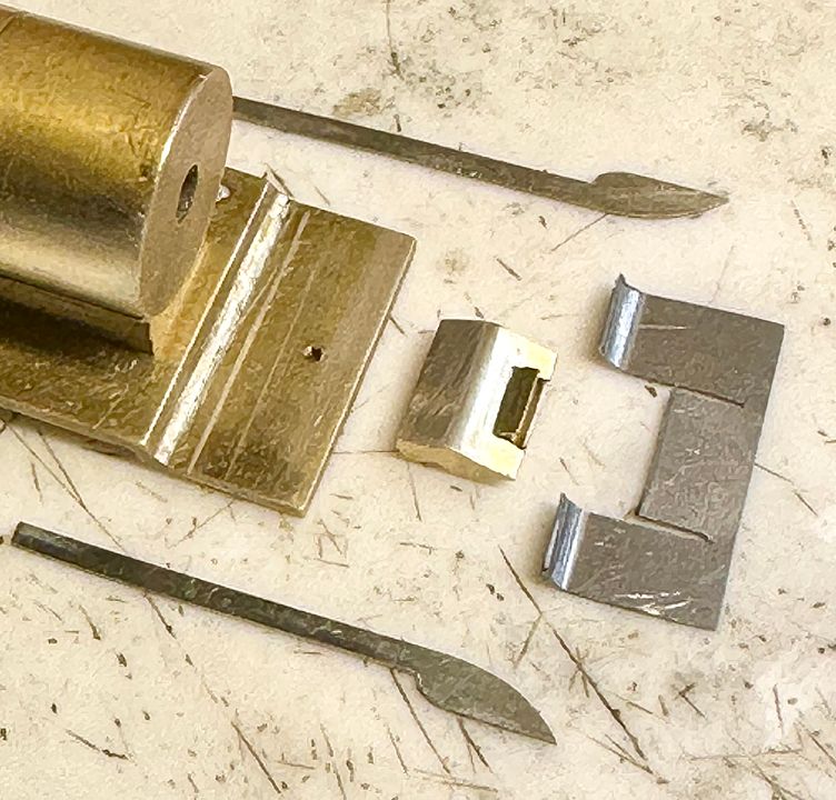
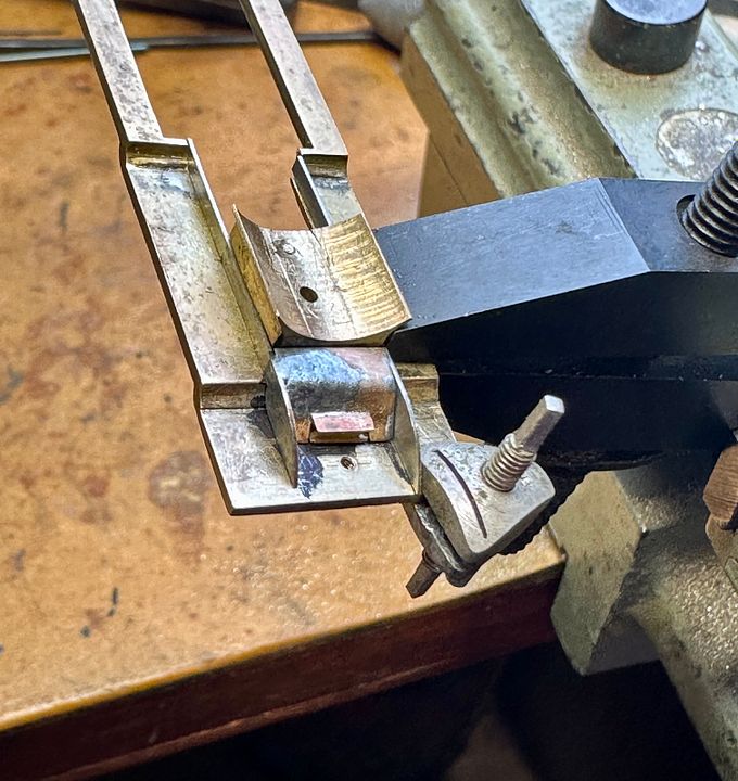
After a very pleasant few days tutoring at the Missenden Abbey Modellers summer retreat, the tender of the skittle alley has made some progress.
The front arrangements are quite different to what I’m used to - a bit like a BR standard in total, but that will become more apparent a little later.
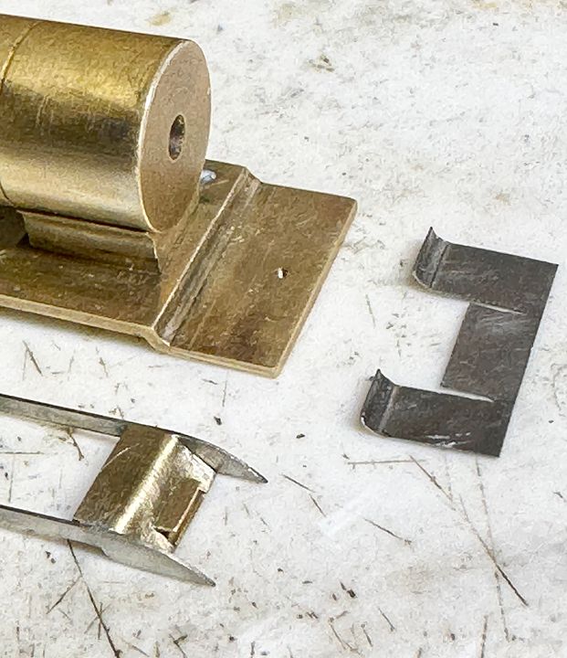
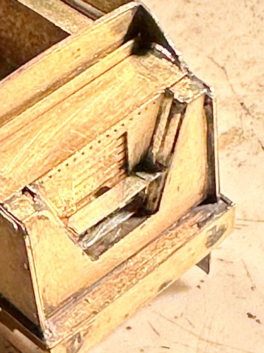
The etchings produce some of the components, but it needs a bit extra to complete the job, in fact a bent up bit of Chiltern Green rail.
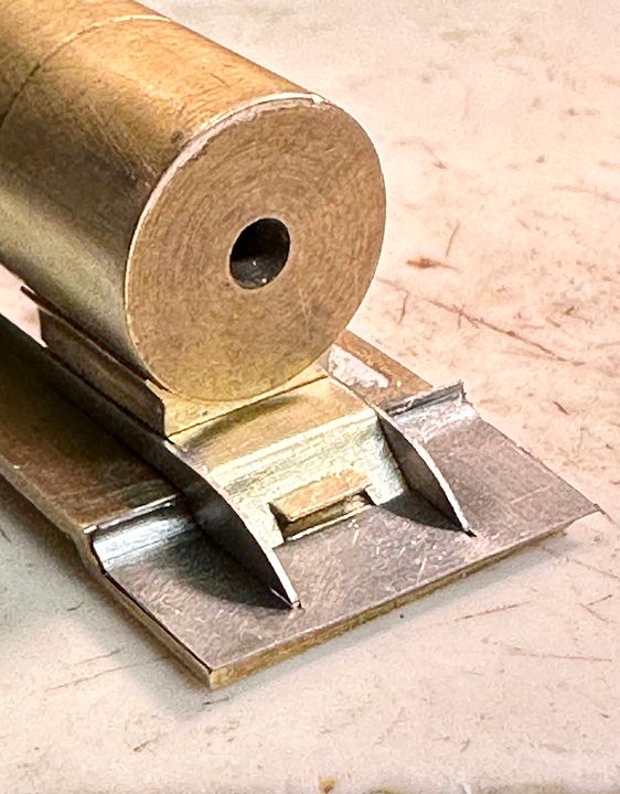
The sub assembly was located at the front, with a slightly increased opening for the drive shaft and then sweated into position.
There would definitely be a step on the LHS to allow the fireman to reach his stowed fire irons so that was made with a scrap of 10 thou nickel silver. It was made to fit across the opening, being wedged in and soldered, but with a break line filed into the strip.
This was then bent up and fractured leaving the step behind. The rivets on the etch could have been embossed from behind, but it was simpler to leave them as dimples rather than pimples. The beholder will still interpret them as rivets…
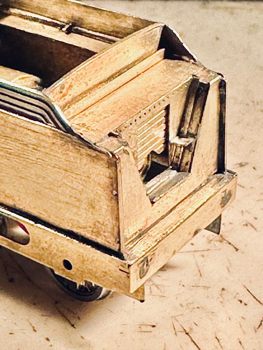
The loco and tender now look much more in proportion, especially with the excellent correct pattern coal guards etched in N/S by Bob Jones. The two-component lifting lugs on the top of the tender were also fitted: they are quite insanely small!
Tim-
18
-
14
-
2
-
There are many ways of making Singles pull decent length trains. The Ivatt / Stirling 7’ 2-2-2 on CF will pull 12 bogie coaches. It has a pivot between the loco and tender that only allows movement in the horizontal direction - so much so that the engine can be picked up by the tender.
The tender chassis is free floating at the front end but pivots at the rear end on a fixing screw and the rear wheels support the back of the tender; in that way most of the weight of the tender can be used by the engine. The rear loco wheels just go along for the ride with light springing.
This avoids the see-sawing effect that could happen with a 2-2-2. The front wheels have two independently pivoted chassis blocks that are kept apart from each other by using a counterbored hole to accommodate the muff which then runs inside the blocks.
These blocks were made out of copper tungsten, but could just as well be brass.
This avoids the need for springing (so taking away traction) and allows for almost independent movement of the front wheels, rather like a Triumph Herald suspension.
My Stirling 8’ Single actually worked better without the tender loaded onto the back - it’s construction was described in MRJ a while back.
Hope this helps.
Tim
-
4
-
3
-
1
-
2
-
-
- Popular Post
- Popular Post
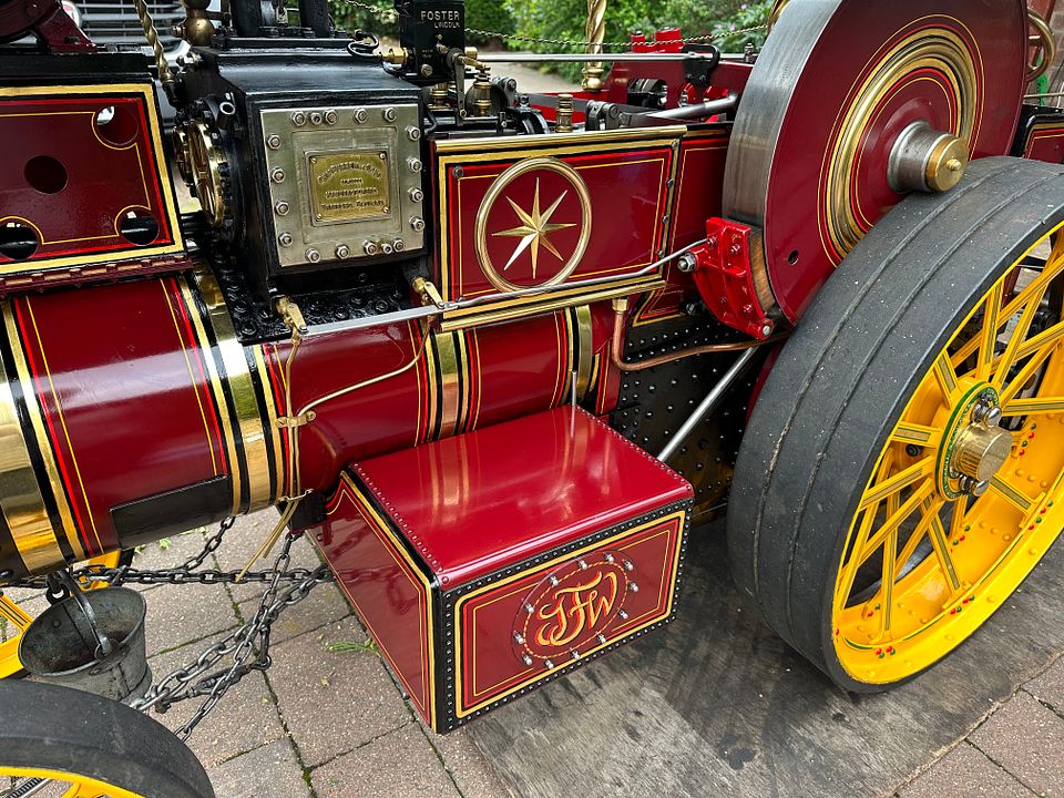
The reason for the quiet time on CF, post Thornbury is that the Showman’s Road Loco ‘Frederick’ has had new tubes fitted, new plugs and a major front end overhaul with gold leaf lining re-done.
This is all ready for a trip to Cornwall for the Boconnoc Rally (28-30th July). Anyone who wants to come along is welcome - Frederick cooks a mean bacon roll on the shovel and an excellent cup of tea.
I will be taking the 2mm workbench with me, but haven’t decided what to do yet. I will have two granddaughters with me as well, so don’t expect too much!
Tim
-
21
-
1
-
A great weekend with great company. Thanks for inviting and putting up with me!
Tim
-
1
-
1
-
-
They did really well. He is very sympathetic to model railways and used more or less the same line previously with me about space & complexity in making a model.
Tim
-
2
-
-
I am currently making a model
if the Raven 4-6-2 class. I had to paint the wheels early on in construction so used the Precision paints colour.
I think it’s a bit too ‘strong’ for a 2mm model (doesn’t really matter too much for the wheels) so I will experiment with lightening it and reducing the blue hues a little.
Tim
P.S. Of course, this engine did run in grey paint for a while…
-
9
-
-
Dipping in to Ww, as one does, I wondered if I was in the correct place with all this Midland talk…
Tim
-
 1
1
-
-
Dipping in to Ww, as one does, I wondered if I was in the correct place with all this Midland talk…
Tim
-
1
-
12
-
-
It’s a bit worrying, bringing the mucky big city to a show with bucolic tendencies (the layouts, anyway).
Tim
-
2 hours ago, Tony Wright said:
On to the front end. Apart from on-shed, none of this is strictly necessary (and certainly not for running on LB).
Steaming would be a bit compromised with the blocked tubes…
Tim
-
2
-
14
-


Revolution Going underground! 1938 stock in N!
in Revolution Trains
Posted
York Road awaits…
Tim