


CF MRC
-
Posts
2,032 -
Joined
-
Last visited
Content Type
Profiles
Forums
Blogs
Gallery
Events
Exhibition Layout Details
Store
Posts posted by CF MRC
-
-
On 28/10/2023 at 16:15, monkeysarefun said:
History has not recorded the name of the bloke who turned up in 1960's sydney and convinced us that we needed an Opera House.
It was controversial throughout its construction, but that was limited to the engineering practicalities, there was never a "we don't need a (($*@ Opera House!" argument. For some reason in those happier more inclusive times we just accepted an Opera House was the thing to have.
It went way overtime and budget, but was funded by a lottery.
I remember the Queen coming to open it in 1973 . I watched it "live" on that Saturday afternoon on our black and white telly while painting my set of 1/76th scale Airfix "Robin Hood" figures that I'd just bought with my pocket money. I remember I used the gloss Kelly Green enamel paint that dad had just used to paint the gutters and garage door with., and they thus took ages to dry and were forever more covered with my " Are they dry yet?!" fingerprint tests..
I have sung at the Opera House, school Eisteddfods were held there and as part of class 5 of Mawarra Public School I got to sing "The Girl With The Black Velvet Band".
In the 70's songs about being forcefully deported from the UK were huge here.
The Opera House is one of those rare things that is impossible to take a bad photo of.
Its a building that just makes you happy to be around, even without the Opera.

Opera house security seal.
It was an engineer relative of my wife, Manuel Hornibrook, who helped in the completion of the opera house. She’s pretty good on quality control on my models too…
Tim
-
 3
3
-
-
I know where you are coming from as my late mother in law grew up on a farm in West Wyalong NSW and we have many relis out there. We do visit Australia from time to time and that seems a long way from nowhere.
One of the main reasons I went into dentistry rather than farming was that our (tenant) farm was only 246 acres which was not really enough to support two families. My father always said he was so glad I didn’t take up farming - I think he was right. That said, I have road steam engine interests that very much keep me in that world.
Tis a small world…
Tim
-
2
-
-
Basically, 50%. Mike Randall (on my left) and myself. A lot the of the team who worked on CG & LH transferred to CF. Many are still involved with a group that is very dispersed & international. The core group who work on the layout and exhibit it are generally closer to London, but projects are outsourced, even to the far side of the world.
The group is far from exclusive, but we do have some good modellers involved and play to peoples strengths and preferences.
Tim
-
7
-
-
Well actually David we might. As there is an ‘incident’ at KX the westbound trains will be stopping at YR and reversing. There might then be a queue for the lifts…
I have just finished modelling the lift lobby. The signalman in the box will be very busy.
Tim
-
 1
1
-
-
That film was made around 1982. CG & LH had a relatively short, but busy exhibition life. I have no idea where it is now, it was sold by the South Devon Railway Centre two or three years ago.
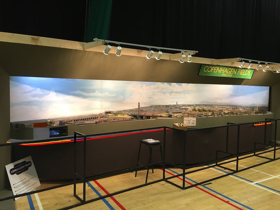
CF will be 40 years old next year, so maybe we should run something at Keen House for the anniversary in the autumn.
York Road is currently taking 110% of my spare time.
Warley is just 19 days away…
Tim
-
15
-
 1
1
-
-
- Popular Post
- Popular Post
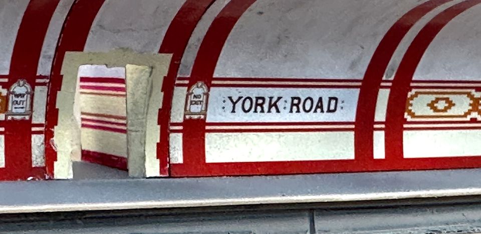
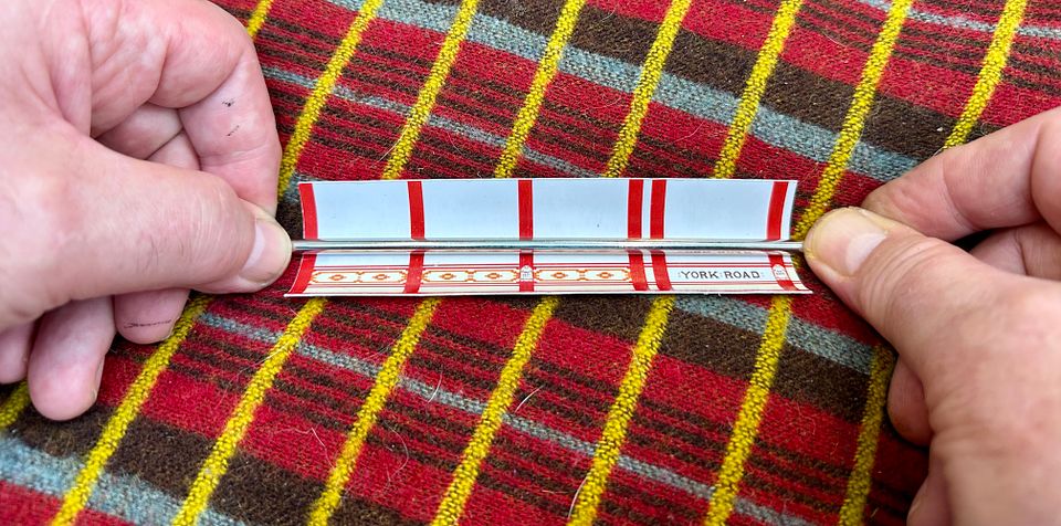
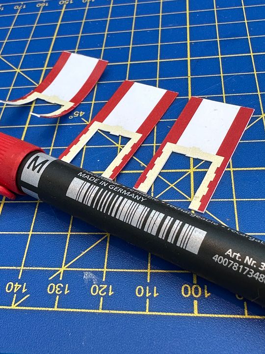
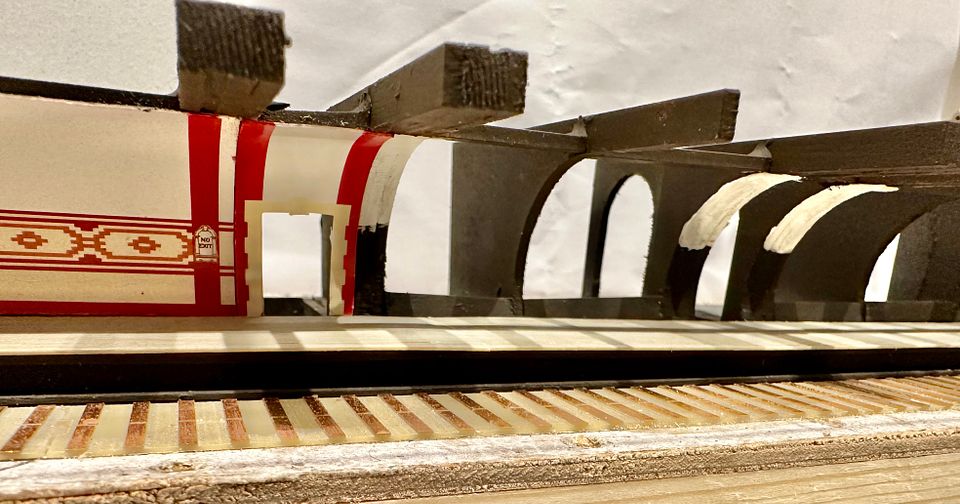
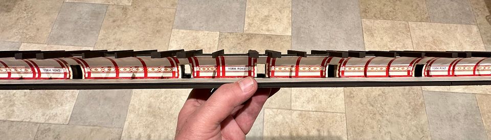
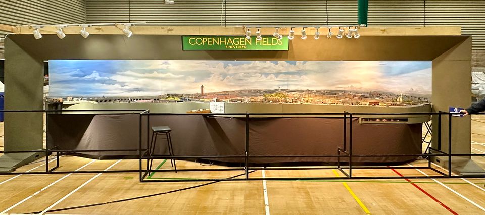
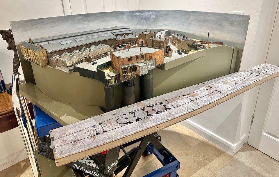
After some fairly steady and tricky work the station platforms for York Road are now sketched in. The 100% accurate artwork for the tiles is courtesy of Douglas Rose, author of the superb and very rare ‘Tiles of the Unexpected, Underground’. The patterns were printed on fairly stiff 250gsm silk-faced card.
The platform surface is currently unattached, just sitting passively in this photo.
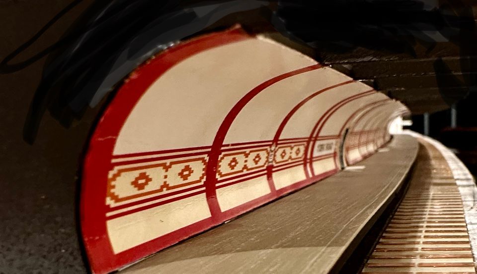
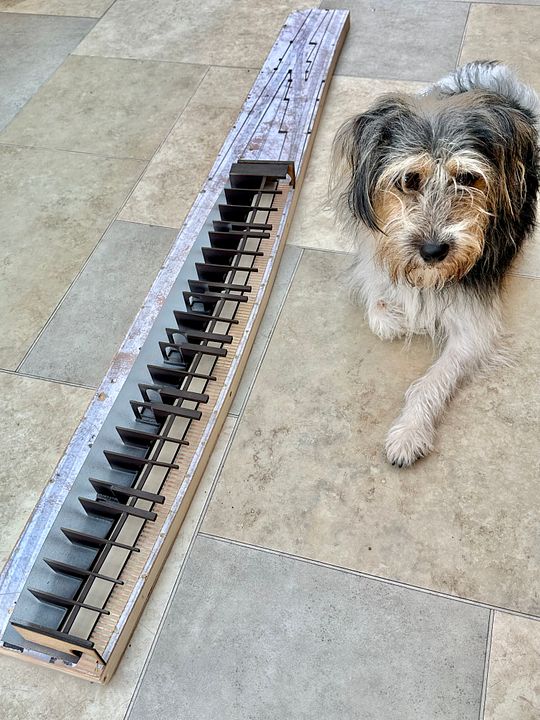
The whole project is complicated by the compound horizontal curvature of the station platform and the tube structure itself. The main supports consist of 2mm MDF ribs cut using the Model Railway Club’s laser cutting facility: these are strategically attached to 0.8mm thick ply sub-base.
Pip is guarding the board here: last time he worked on YR he was but a puppy.
The tiled card was rolled on a soft cushion with a polished steel rod. It would probably have worked better with Piccadilly Line moquette, rather than Routemaster.
The adverse curvature of the station platforms is accommodated by breaking the tile run either side of the crossway entrances. These entrance sections were touched in with a red marker pen to avoid unsightly dodgy edges.
The area above the dado was painted white, just in case there were any gaps showing between the card sections.
The 700mm long fully tiled walls do look rather pretty (if I do say so myself) and bring a station back to life that closed 91 years ago.
There is a lot more work to do…
Tim
-
26
-
 2
2
-
 15
15
-
3
-
One day maybe we will see a decent model of a V2.
Tim
-
2
-
3
-
-
Your view is to the SW, Tony. Highgate is to the north. The copper cupola is just visible above St Mary’s Free Catholic Church (a weird sect I hadn’t heard of).
Courtesy Phil Parker
Tim
-
14
-
 1
1
-
-
The chapter house in St Thomas St actually contained an operating theatre extension of the original St Thomas’ Hospital which presumably communicated with the wing of the hospital that is now the Post Office building. The coming of the railway was too close for comfort for the governors of St Thomas’ and so they upped sticks and moved to Lambeth, opposite the Palace of Westminster. The other wing of the hospital was demolished, leaving just Guy’s Hospital at London Bridge. The two hospitals re-merged in 1993.
All this has absolutely nothing to do with railways, but I do have a fantastic train set to look down on from Guy’s Tower.
The Chapter House and Southwark Cathedral are in the bottom right hand corner.
Tim
-
15
-
-
5 minutes ago, lezz01 said:
The one on Highgate Hill? I live really close to Holy Jo's I can almost hit it with a rock from my patio.
Regards Lez.
That’s the one. The distinctive copper cupola stands out in the distance.
Tim
-
1
-
1
-
-
We have four places of worship
on CF, five if you include Holy Jo’s on the back scene.
Tim
-
3
-
 1
1
-
-
A sad loss. ‘Top Shed’ was our go-to reference for Copenhagen Fields in the early days (and still is). The copy in our layout cupboard is well thumbed. It is a shame that he never saw the layout.
Tim
-
2
-
-
The obvious choice is a buckjumper. Why make life easy for yourselves? You are doing one in 4mm scale.
Tim
-
2
-
1
-
 1
1
-
-
A good bloke to chat to at a show and always keen to help when ever possible. My condolences to his family.
Tim
-
Not really my specialty knocking out wizzies, Jim, but I did use that technique when I was an assistant house surgeon.
Tim
-
1
-
-
2 hours ago, Grafarman said:
To me it's amazing that over the years the various boards that make up CF haven't warped or shifted but still connect so cleanly, given that some are quite a bit older than others.
I still haven't seen CF 'in the flesh' - I really must make that my goal for next year...
David
David, our baseboards and joiners are ‘over engineered’. The main baseboard structures are based on a box beam type construction, developed by Mike Randall, using high quality thin birch ply. This has stood the test of time (40 years in 2024).
Our upcoming exhibitions are:
Warley November 25-26thRailex Buxton 6-7th July 2024
Ally Pally March 2025
Manchester December 2025
York Easter 2026
Swansea September 2026
If you want to see the layout up close then MRC Open Days sometimes feature it. Perhaps we should do a special 40th birthday do at Keen House in the Autumn of 2024.
Tim
-
5
-
3
-
-
1 hour ago, Kylestrome said:
The "Instruments of Persuasion" are wielded in the most benign way possible, I presume?
David
But of course David! A sharp tap with a Mallet is sometimes useful to overcome stiction.
Tim
-
1
-
1
-
-
- Popular Post
- Popular Post
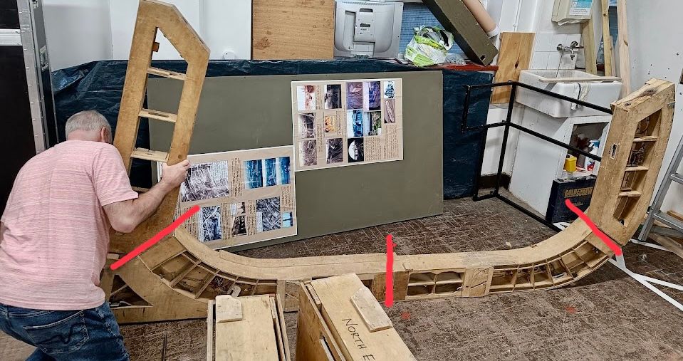
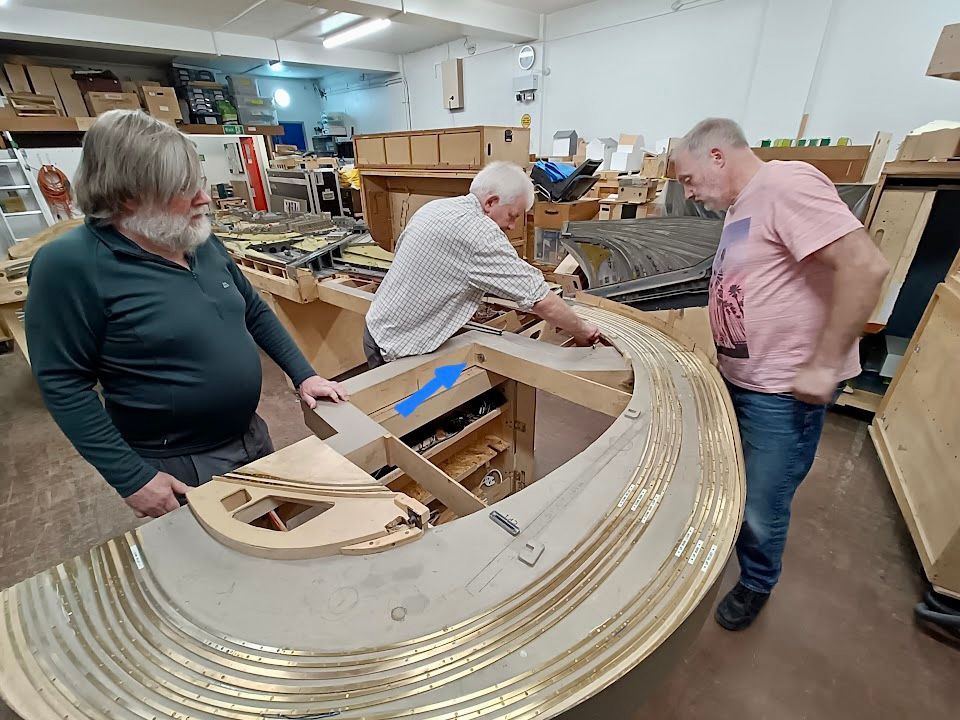
And now for something a little bit different. When CF was last being erected Justin Colson took a few pictures of the various stages involved for setting up the main ring of baseboards. I don’t think anyone has shown how layouts get assembled on RMWeb, and if they have, it is very unlikely that they are as complex as CF. Many of you will have seen all this happening at shows; please forgive me if it’s a bit boring. So here goes, with a few comments along the way.
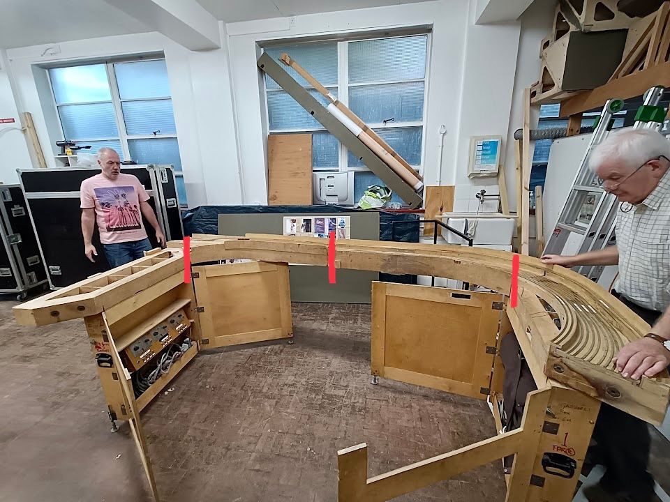
The first part of the layout to be made was the north end and that is where setting up begins. There are four fiddle yard boards that get bolted together as a ‘C’ laying on their side. The leg boxes that these sit on can be seen in the foreground, the redlines show the baseboard joints.
This whole assembly is lifted onto the leg boxes which are set out at the correct distance using a length of string as a gauge (at Keen House there are marks on the floor.) The leg boxes also act as storage containers and have levelling feet at the bottom.
Here, Simon Humphries is demonstrating that all bolts are equal but some are more equal than others, with Rob Stewart looking on whimsically. Very occasionally a longer bolt will be needed in a particular joint - these ought to be marked - but where’s the fun in that?
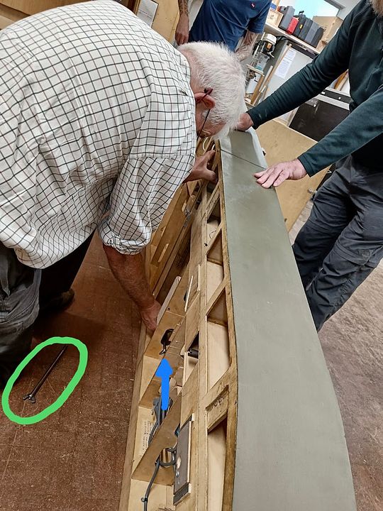
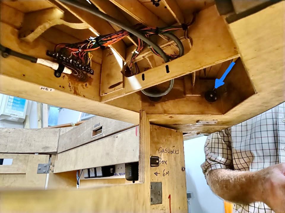
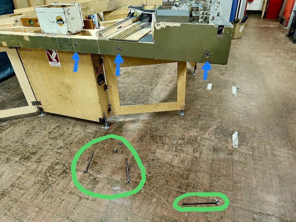
The two front Holloway Bank boards are removed from their case and bolted together, whilst resting on their sides on the floor. Our 10mm bolts are a precise fit in 8” steel tubes in each board, ensuring reasonably reliable alignment and strength. The direction the bolt is inserted can be seen by the blue arrow. The second bolt is on the floor (green circle).
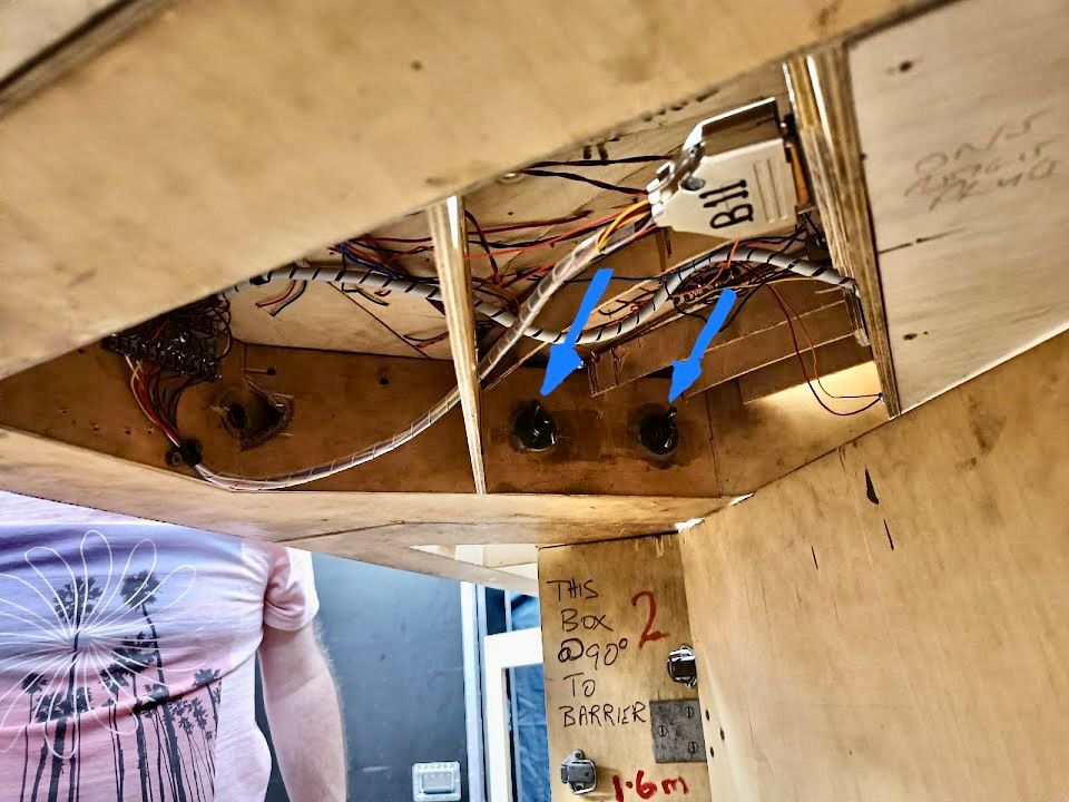
The whole of the HB front is then lifted onto the open gate legs and two bolts inserted at each end from underneath. At the south end the bolts both go in the same direction.
At the north end they go in opposite directions. Our next job will be to mark up bolt direction on the layout underside. Getting these bolts in place can be quite a struggle because the floor may not be level or flat.
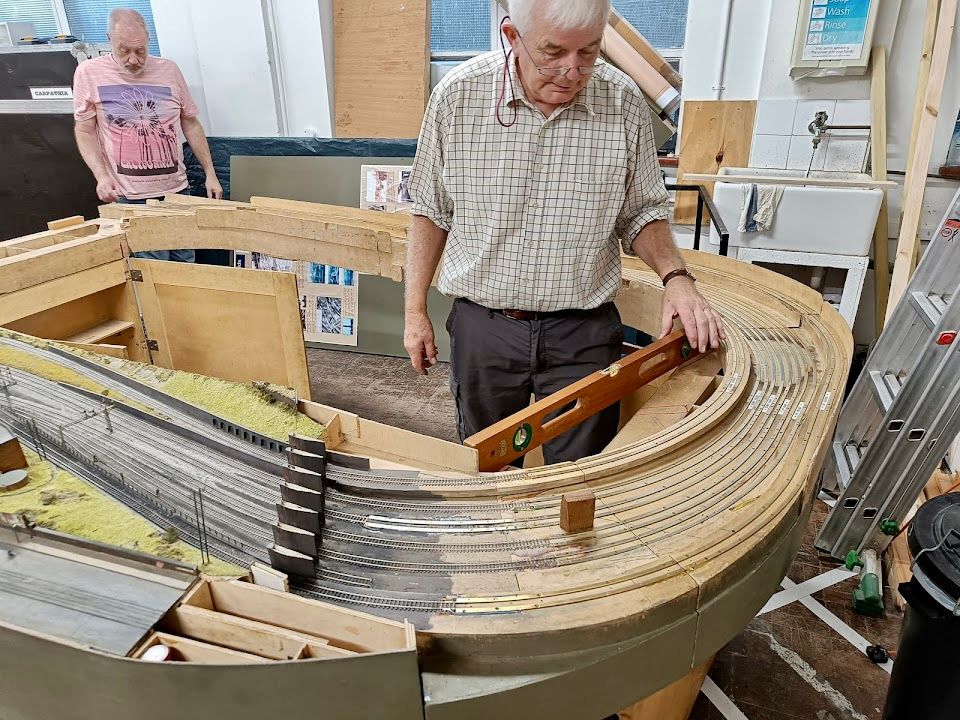
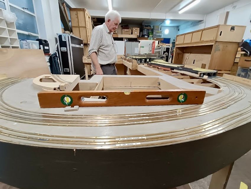
Once the first ring is set up, the gates are taken away from supporting the layout and it is then precisely levelled, using a bespoke spirit level on known reference marks.
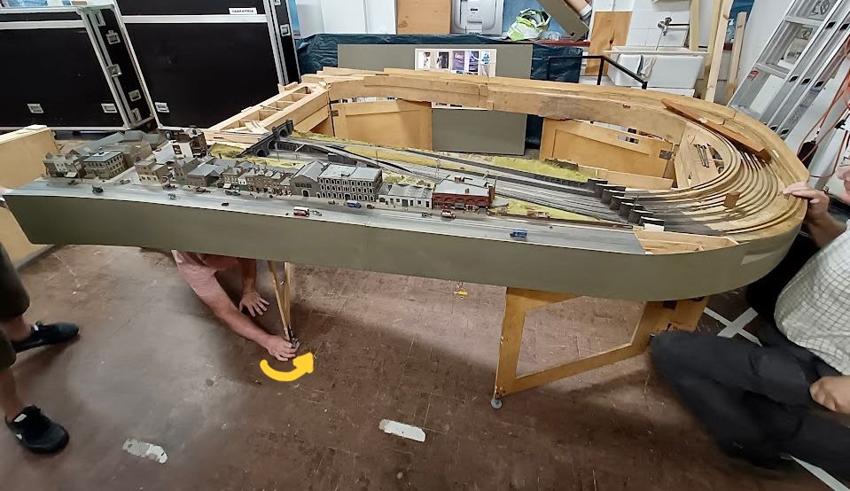
Once these four feet are adjusted to make the boards absolutely level, then the gate legs are moved back under the layout to give more support, taking up the level with their own feet (yellow arrow).
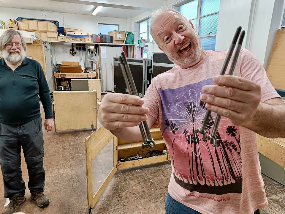
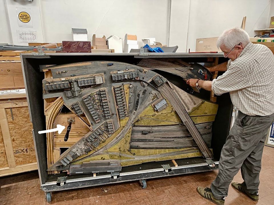
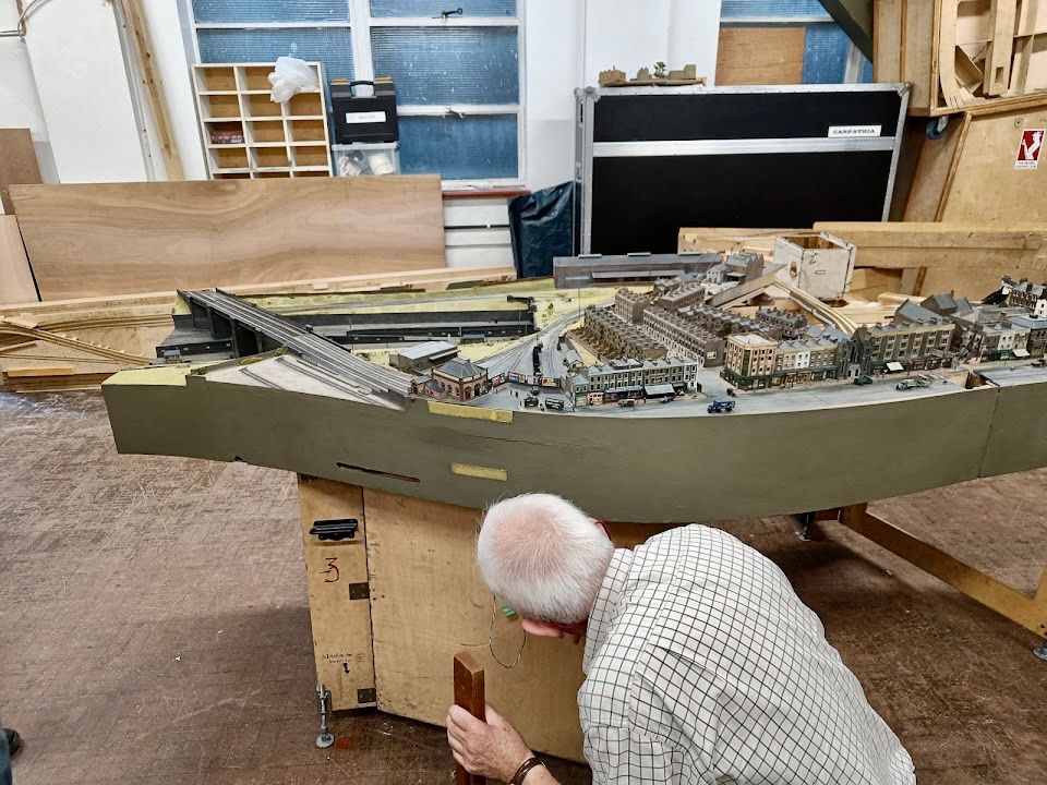
The next stage is to put in place the massive Belle Isle board. This travels in its own case and is quite tricky to handle. It also travels with the NLR link board which can be seen in the top left of the box. In order to lift it out of the box there is a massive truncheon-like rod which is screwed firmly into the framework (white arrow - it also has other ruder names) as well as a steel ‘bale hook’ that engages with a hole in the RH baseboard end. Two individuals then lift the board vertically in the box whilst another two move the box away from the board. It is then rested on its back face awaiting assembly.
Prior to lifting into place the three baseboard bolts and nut closers are laid out on the floor (green circles) whilst the fixing holes are show with blue arrows. For the first ten years of construction, this was more or less the full extent of the layout.
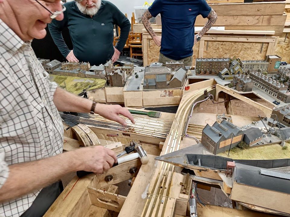
The longitudinal position of the leg box supporting this board is located by using the important piece of string with marks on it. A team of three-four people then lift this board into place, resting a lip onto the northern boards. Meanwhile, a brave soul goes underneath and slips in the long steel bolts and does up the nut closers. It is then levelled, paying attention to its level in the L & R as well as front to back directions.
It is important to check out the central baseboard joint for all alignments on the six GNR lines that cross it as well as the hidden NLR link board. Various ‘persuading’ instruments may be called in to play.
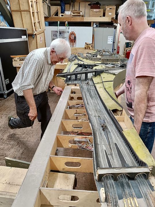
The pace of assembly now accelerates as the Belle Isle south board is daisy-chained on to the big board. This is just about supported by another leg box and fold-out gate leg. Again it is checked for level, against known reference points.
Going round the corner (into KX) we have the Sopwith board. Why that name? Well it looks like the tail plane of a Sopwith Camel aeroplane. It is bolted in two directions to the Belle Isle south board.
Levelling is, as always, critical.
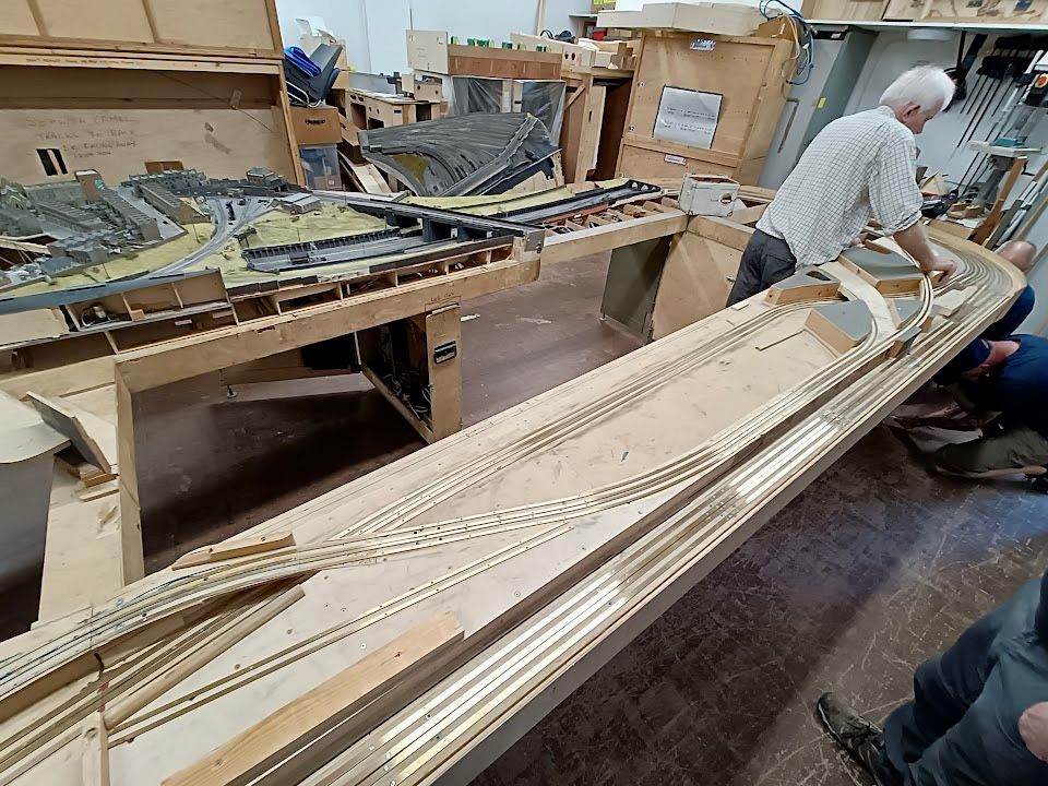
The final behemoth baseboard that completes the ring is the 10’ x 2’ Big Fiddle Yard board. This is a four person lift and slips in north end first and then the south. There are precision joiners at the north end and it’s on the ‘to-do’ list for the south.
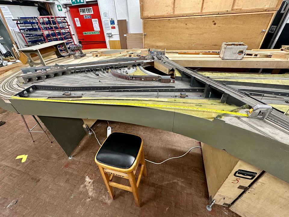
The final operational boards to be inserted are the NLR link board (and fiddle yard) and the KX Goods board which covers a large area and locks into place next to the NLR viaduct and has three precision dowel bolts locating it to the BFB. The ruler in this view shows a 6’ length for scale.
So there we have it. The shear size of CF makes it essential that it is assembled in a totally reliable and reproducible way. It is quite hard work to set up (MRC membership is cheaper than a gym) and maybe it’s now obvious why we only attend two shows a year. Of course, this is only about 2/3rds of the story as all the scenic sections, back scenes, ‘Toblerone’ lighting proscenium, barriers and other add-ons such as the tube are there to complete the scene.
Apologies for the exceedingly long post and a self-administered pat on the back for anyone who got to the end…
Tim
-
33
-
1
-
12
-
 1
1
-
2
-
11
-
14 hours ago, D-A-T said:
Won’t the Exhibition/Hall Managers have something to say about you digging up their hall floor to get your deep underground lines in??!! 🤣I hadn’t noted the red lines on the floor and also the out of date nature of that photo; the whole of the south end has undergone a lot of work since then.
Re: Andy’s question, the last baseboard will be the one that takes the tube in front of the cemetery building under Belle Isle & the NLR.
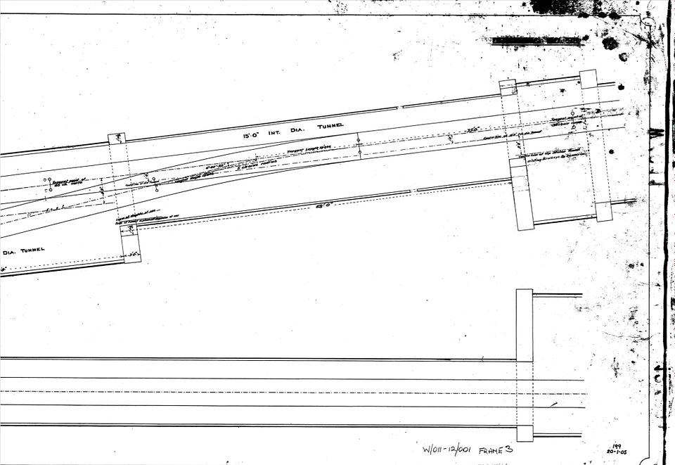
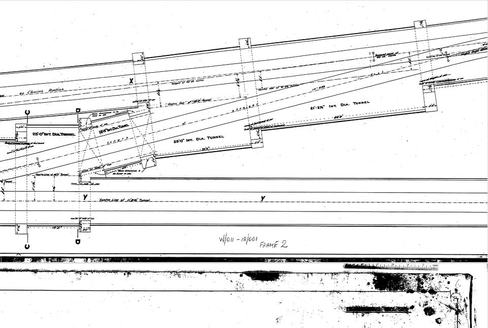
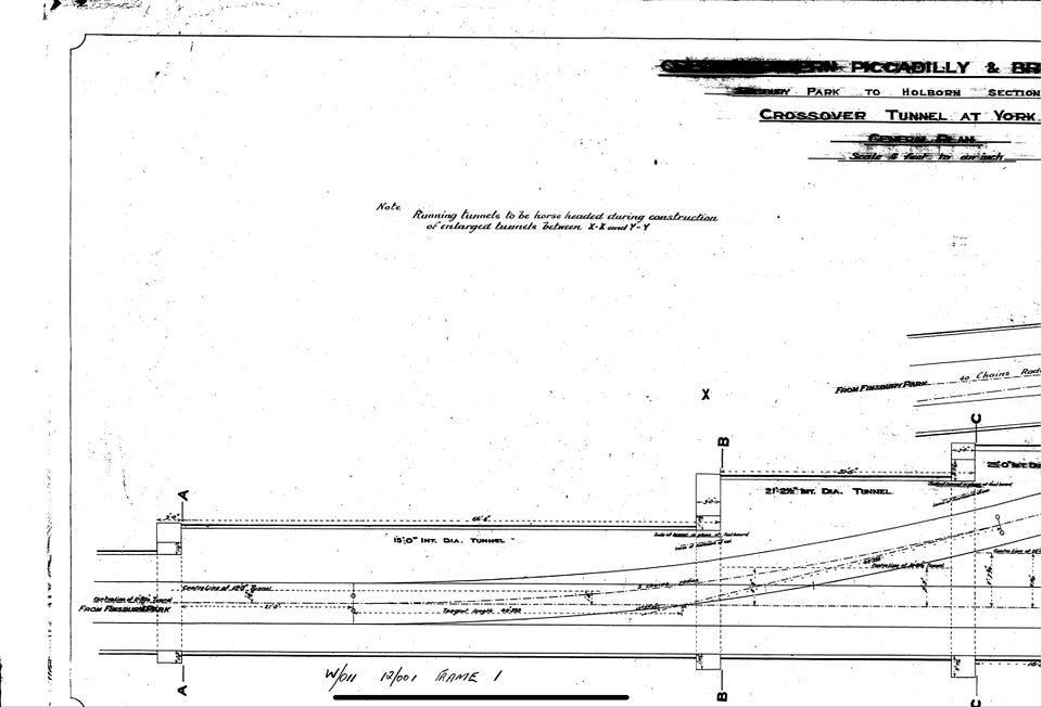
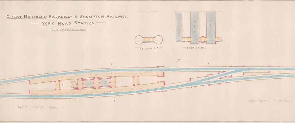
Re: Nick’s complex tube tunnels and for illustrative purposes, (please do not copy and publish elsewhere) here are the plans showing the crossover at the north of YR. There was a signal cabin at the north end of the northbound platform, but this would be out of sight. I am quite tempted to flip it to the visible platform.
Quite a challenge and all this will take a while to complete.
Tim
-
11
-
1
-
-
The tunnels will have cutaways to show the lines / trains. In the next stage this will include the northern approaches to YR station with the track shown in red in this image. (Edit: not the red lines on the floor!)
The track height is actually about 15’ deeper than it should be, as we are constrained by the depth of our baseboards. Foolishly, when we were planning the layout 40 years ago we hadn’t thought that York Road tube would be modelled…
Tim
-
13
-
1
-
1
-
-
It will be a separate layout Kevin, as the logistics of joining them up is not trivial. It will initially just have the platform modelled with a train coming into the station and then returning north. There is an incident causing a blockage at KX! The next stage will have the tunnels modelled and crossover to the north of the station. We have all the drawings for this from LT. I have a cunning plan for making the tubes…
Tim
-
7
-
1
-
-
- Popular Post
- Popular Post
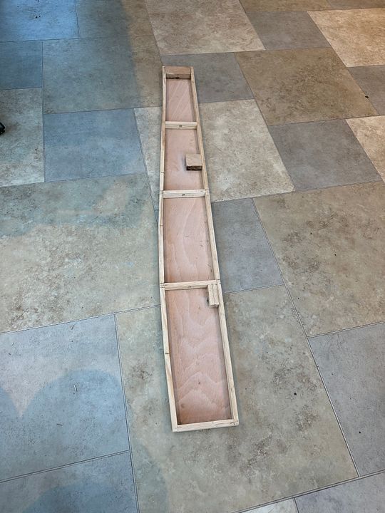
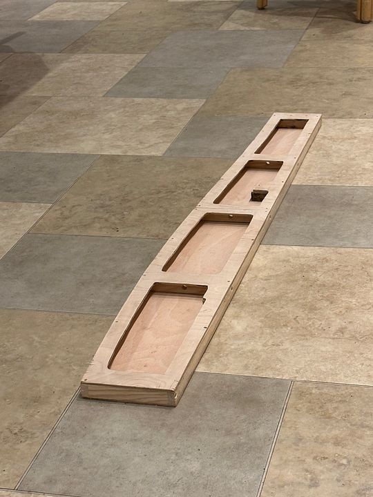
As promised, construction has begun on the York Road tube platforms baseboard. This photo shows the board just resting in front of the tube station: in its final form it will be below and centred on the lift shafts.
The prototype track plan (courtesy LT Museum) was printed to size and stuck to some 4mm ply. This was then tried for position on the main layout and fixing hole positions determined.
The ply top was then framed with 12x21mm pine strip wood screwed & glued in place. An oak block was incorporated at the end where the next board joins on: decent wood is essential for holding baseboard joiners in a repeatable position.
This was left overnight for the glue to set and then a lower skin of 4mm ply screwed and glued onto the pine wood frame. This I beam and stressed skin design makes the whole construction immensely rigid and pretty lightweight.
The track base will be 46mm below the underside of the layout with a spacing rib 75mm deep fixed to the back edge. Quite interesting really that this is the penultimate baseboard to be built for CF.
The planning of the station platform itself is well advanced with laser cut ribs and completely accurate tile artwork already for fitting.
Tim
-
21
-
1
-
16 hours ago, Caley Jim said:
Derbyshire? The North? That's almost the Deep South from where I'm sitting!
Jim
Well the Scottish army did get that far south, once…
Tim
-
2
-
1
-
6
-
-
- Popular Post
- Popular Post
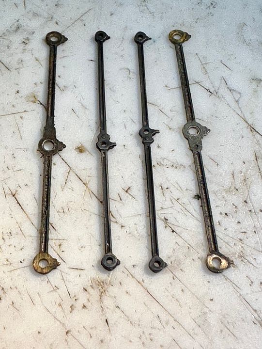
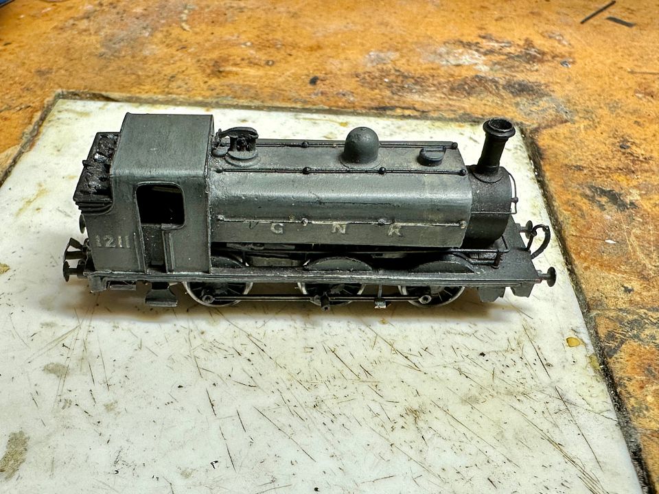
I have been working on an old timer today - the GNR J13 that Mark Fielder made from an old Beaver N gauge kit. It trundled around Copenhagen Fields for hundreds of miles, but ‘failed to proceed’ a few shows ago. The chassis is a heavily worn Graham Farish 57XX block, fitted with the late Neil Ballantine’s plastic moulded fine-scale replacements and a Maxon motor with 1:4 gear box, driving the original worm set. However, it is the coupling rods that have worn the most.
The holes had worn to be at least 50% bigger than they should be. They were replaced by a new set made from 2mm Scale Association etches.
What is quite remarkable is that the new rods fitted without any adjustment. The engine now trundles up and down the test track with a slight ambling gait, but then it always has.
It will be good to have a work horse back in the traces for our next show at the NEC in November. Attention is now turned to making the York Road station tube platform and hopefully another loop on the down goods line.
Tim
-
19
-
1
-
1
-
1


Copenhagen Fields
in 2mm Finescale
Posted
We visited West Wyalong in April 2022, for a family get together (actually to inter MiL’s ashes with her parent’s graves at Barmedman) - it was a great party. Australian railways are fascinating but I have more than enough distractions already! I expect we might go out again in the next 2-3 years.
Tim