


844fan
-
Posts
348 -
Joined
-
Last visited
Content Type
Profiles
Forums
Blogs
Gallery
Events
Exhibition Layout Details
Store
Posts posted by 844fan
-
-
Its in chronicles of boultons siding which had three chapters on strange geared engines, this book has all the same drawings and is easier to source at a better price except you don't get as much of the back story of the locos https://www.amazon.co.uk/dp/0853613974?tag=vig-21y
Hmm I just may have to see if I can get this shipped from Amazon UK to the US. I want this book now very much so more than I did when I first heard of it. Sadly not many listings of it on Abebooks or I'd use that.
a friend of mine recently showed me another similar book full of loco drawings, all sorts of early mainline and industrial
Sam my friend please find out the title unless it is the Boulton Sidings as well. I would love to see these drawings. Pitty that I can't talk with your friend as easily as I can you sounds like a cool person.
-
This is CP no. 503, a 4-cylinder compound 4-6-2, one of a batch of eight built by Henschel in 1925 (nos. 501-508). This locomotive was rebuilt in the semi-streamlined form shown, at Barreiro Works, in 1940, It was converted back to its original form in 1948. The type survived until 1971, but none are preserved.
I have side elevation drawings of the non-streamlined form (ironically from 1946, when 503 was still semi-streamlined). I believe photos of the streamlined form are quite rare.
Pitty that there are so few photos of it's class streamlined. Would you possibly be willing to allow me to see the line drawings you have from that I'm sure I can make a reasonable take on the shroud. If you know anyone with photos of the streamlined versions ask them if I could see them too. Only asking you understand I fully realize why yould rather not if that is how you feel just thought I would ask.
-
But I'm pretty sure Pugsy didn't have vertical cylinders, looking at the drawing in chronicles, it seems I was completely wrong and she did in fact have springs, my apologies gentlemen, she wasn't a bad little loco by any means, she could pull 25 wagons belonging to the LNWR, very respectable for a loco weighing less than 8 tons
Not to mention I think even the Loco Sam linked has springs if I'm looking at it right you can see leaves behind the front driver. 25 wagons of a standard size is quite strong for a small engine indeed. You mention a drawing where is that from?
-
Hey all,
Was recently talking with a good friend from Portugal and he showed me a photo he had gotten from his Railway Club. He compared the engine to the A4s of Portugal though that was at their appearance being very stunning for the most part. Anyway I want to learn more on said locomotive even though it is a broad gauge it's quite the looker.
Photo here used with permission from my friend Walt:

IMHO this engine looks lovely and it's probably just me but if Thunderbird 1 was ever a loco I think this would be a great base to start off from.
Like I said I don't even know the class number let alone her name so any help her is much appreciated.
Thank you everyone,
844fan
-
 4
4
-
-
Methodology is as follows. Chuffs are actually a sort of exhalation with an 'urrgh' overlaid with a 'Tfffa' sound, the t being softer as the cut off is wound back and the regulator closed with the 'a' at the end being cut back and diminishing as well; 4 per driving wheel revolution on the noon, and 3, 6, and 9 o'clock positions, but slightly uneven with a bit of 'swing' unless the loco is fresh out of works.. Full on starts with 56xx or 42xx are a full bodied 'whoompfff', GWR vacuum pumps are a sort of 'tss tss tss 1 per pump stroke, i.e per revolution of the driving wheel. Buffering up is a sort of 'cloc', 'cloc phfffff very slightly and fading in the case of pneumatic buffers. Whistles are a sung 'ooo', with rising or falling pitch at the end or to suit, guard's whistles are a sort of 'tree'ee,eeup' as high as I can go. I do not have the whistling skills to do these by whistling, and they are not very good. A sort of 'urghhh tick tick tick', fading in volume, is the noise for a destroyed vacuum, and a bit of a 'tick tick, tick... tick' for recreating it as the brakes blow off. Bit of a 'clonk' as a coupling is dropped on to a hook sometimes, and 'linggggg' as it hits the underside of the wagon when it's uncoupled, but not for screw couplings.
Blowing safety valves are a problem, as I can't sustain them for more than about 10 seconds without running out of breath, but a similar loud 'shhhhs' if fine for ejectors , sometimes developing into a cyclic 'fssshht fssshht fsssht' as the loco moves off in a cloud of imaginary steam.
Who needs TTS.
(actually, me, from the sound of things...)
Haven't managed to distort my vocal cords or exhalations into a passable check rail scream yet.
I intend to cut indentations into the rail surface at suitable intervals with a slitting disc to generate wheel beats.
Thank you for the Vocal Foley advice my friend. I'll try to put it to good use.
Smart idea for a railway without the Tricity Trop of fish plate bending and clnking is hardly a proper sounding line.
-
No. With geared drive of this sort there can be no vertical play in the driven axle, as it would either shatter the coupling rod or push the piston through the cylinder front in certain situations. In a normal locomotive, the vertical play in the axle allowed by springing is absorbed at the crosshead pivot, but cannot be so absorbed where the play is in the same alignment as the piston. Next time you have a look at 844, you will be able to see what I mean; imagine movement of the coupling rod in the same direction as the piston. There is no capability in the crosshead pivot to take it up, it just gets gets transferred directly along the alignment. In Pugsy, there is a vertically mounted cylinder with the piston driving directly downwards via the gears to the (rear) driven axle. I suspect she wore her big ends rather badly rather quickly unless she ran perfectly smoothly on perfectly smooth track, and she doesn't look the type to me...
In geared locomotives such as Sentinels, chain drive allows a degree of play at the expense of chain wear, like on a motorbike, and in the likes of Shays, Climaxes and so on the drive shafts pivot like cardan shafts and allow the required play, but one cannot see how Pugsy achieved this and she probably didn't...
You know I should of realized that. Why is it that when someone points out the obvious answer to your question you immediately realize that same answer was in your face the whole ime and want to face palm?! So that would also mean that the old Beamish coffee pot would have no springs either as that most certainly is not geared.
Hmm given that she would work slowly I bet a skilled driver could keep her rough riding under control. Just got to treat her with respect and some skill but yeah it explains why there are few Vertical cylinder setups that are geared like this and would use drive shafts and chains to allow for springs. Much more the pitty since these little engines are quite adorable and look quite hardy.
-
Not to mention she (or he?) wouldn't have had springs, what with the geared drive, buyers did shy away from the poor little engine, shame
Could be fitted with them at one point couldn't she? I'm no expert but can they be given them?
-
Confession time. I live alone (the following may go some way to explaining why) and have nobody to mock me when I'm operating my railway, so I happily make chuff chuff noises (4 per driving wheel revolution; very good for judging speed) and can reproduce a GWR whistle, by singing not whistling it, including the 'bending', to my own satisfaction. Your approach, when you have ironed out the problems, will probably attract less out and out understandable disdain and avoidance of eye contact with the nutter from your fellow creatures...
A locomotive involved in shunting whistles quite a lot, firstly because it's in a good mood of course, but mostly to communicate to the signalman that it is clear of points or signals or to a shunter on the ground that the driver has seen and understood his handsignals; it will also give a toot before moving off from a stand, and it's normal whistling duties warning people around the track of it's presence or imminent approach. Large yards had whistle codes to indicate certain sidings or movements to signalmen, and, with a few locos working at the same time, could be sonically 'interesting'!
I find absolutely nothing wrong with this not even the slightest. Heck I do it and I live with my family though I must say I'm impressed if you truly can match the piston strokes timing so well I often make it only ever half a turn and I know a engine puffs four times per wheel turn after all they are quartered for a reason (and frankly again back to Thomas is the largest complaint I have in the CGI series. The engines except for the one based off Rocket all have their coupling rods dead even so if one side is at 12:00 the other side is too. Have none of those animators ridden a bike? that's the only reason we can push the peddles is they are off set but to be fair on inside cylinder engines the pistons are quartered though the valve gear is completely unrealistic.) So props for that.
My reason for it is I've always liked trying to mimic sounds of things I like. The hiss of steam from a drain cock, the clanking or thudding of giant robots (Which I can imitate the sound they make when transforming too.) and so much more. I have deep respect for the foley artists and one of my favorite jokes in any movie is Spaceballs with the guy imitating the Radar and intercom mad respect to that man as he made a career of it. One of the reasons I want to be a Voice Actor as well as writer.
The DCC Sound thread, which includes at least someone who has made his own files, may have some expertise to offer. I should have noted earlier that there is a better place for this discussion.
Give them a chance to comment? if you 'report' this thread and ask politely for it to be transferred there you might learn more.
Hmm a good idea. I'll try and figure out how to go about it.
The problem with recording my chuff chuffs, whistles, brake squeals, vacuum pumps, block instrument bells, and so on is that they sound fine inside my head. You know when you hear your own voice recorded and it doesn't sound like you? Well, that's why my noises would sound wrong if they were recorded from anywhere outside my head. And I'm not sticking a microphone inside my head or anywhere else inside Johnster's insides; there's enough trouble, and plenty of noise from the creaking woodwork and grinding gears, in there already thank you very much.
That is my excuse and I'm sticking to it!
I can, however, thoroughly recommend developing your own repertoire, modulated and pitched to your own requirements. If you can do a reasonable chime whistle, A4 style, you will have achieved something I have never managed. We will all be most interested to hear it! I can do a pretty good London Underground/Southern Electric Westinghouse air pump chunka chunka chunka for a GW man, though...
As a GW man, I can't do walcheart's valve gear clonks properly either, 15xx or no 15xx.
Don't I know it. I knew my voice sounded young for my age due to hormone troubles I only learned I had. But hearing a playback it is kind of weird how I sound to my own ears but that may lie in the engineering of the audio too. I mean I do a spot on impresion of Strong Mad and Strong Sad from Homestar Runner both ways and my friends say I imitate a VA of Sonic The Hedgehog (No not Mr. White this guy we jokingly call Irish Sonic as we know he is from Ireland but we forget his name too often) but in my head it sounds off so I suppose it's one of those cases of "That sounded better in my head." for all of us who like to make sounds.
-
I'm not sure you can do this in Audacity; mind, I only use it for music recording and conversion to mp3 format, and very basic editing. But as far as I can see it is an editing app, not a sound manipulation one, and you might be better off with one of the sound creation apps. The only way that you might be able to achieve longer whistles with Audacity as far as I can make out is to stitch edit shorter bursts together, which would I suspect be difficult to do without ending up with a sort of hiccuppy effect...
Indeed I'm looking into every option but I've tried that method stiching together and it has that hiccup like if you take sections of a soundbyte to create a new sentence. YTP kind of stuff and that is not what I want. Also I forgot to ask this before but is there a easy way to find out what note is being played? In this case it is a single chime from a small loco I know most whistles use multiple chimes to achive the note they produce but this is only a single.
Start small for pitch checks.
-
Bit much tha' init'?
 was 8MT even a real classification for any standard designs or for that matter nonstandard.
 -
Hey all,
Got a bit of a technical question for all my fellows who know sound effect engineering than I do. So recently I got some audio and video clips at a local convention called "The American Thresherman's" this event is held in August and October around here and is a celebration of steam, petrol/gas, and diesel based farming machines most of which are Traction Engines they even have a small locomotive like the R&ER 15 inch running. Now as I said I got some clips from the show and want to use them for a project I'm doing.
My problem is I only have short chirps of whistles blowing like what you'd here in (please bear with me on my example here best example that comes to mind.) Thomas and Friends when the engines would pass each other and whistle a quick "peep peep" as a greeting. But I want to also have Long blasts od the whistle note for all whistle signals I may want to or need like a Long bellow or a even shorter chirp so I can piece them together in the proper codes.
I unfortunately have not yet figured out how to do this whith the Audacity editing program with out it sounding clearly like I made it off. I'm not sure anyone here knows anything about the subject but I thought I'd give it a try see what turns up.
Thanks for the time,
844fan
-
Now I must put my ten pence (Ten Cents is a bit much seeing thats a whole Tugboat
 ) for me modeling is going to be fictitious on the fact that no mater how hard I would try I can't make a exact replica of a real railway. One thing all model lines have unless you have the room for something like the RG&ER 15 in line your are stuck with either a loop or a dogbone.
 Also to me the point of a railway is to make it your own sure base it off real practices like if you make a Quarry make it look functional and have the towers, hoppers and whatever else was needed but don't limit yourself just by real locomotive count. I'm a writer and I have to say I am also young of heart so my railways will always have certain impossibility to them (For example my planned CVR line has three American locomotives at the start of it's life. All are 19th century prototypes built before 1900 and all have been rebuilt heavily to a Doncaster style with running boards and such. I also plan to have the rebuilt 0-8-0 form of the Decapod Tank on my line.) but from all I know these things were not impossible but Improbable or Unlikely to have ever happened but these small breaks add to charm. Heck I dabble in Freelance design but not for anything beyond a Industrial.
My honest humble opinion is the same as a man I respect deeply who had a fine set of models. Even finer bridges for them to run on. Just read my signature you'll know what I'm talking about.
-
ive only said i would like to build it as the replacement for the planet for the back dating but only after getting a 30's tractor
for the louvre, i dont know yet
I am quite sure you'd figure it out. The little engines are both now on my want list! But I fully understand the money situation while mine is a slight bit better for the time being I can't spend like a madman either.
Edit: Hold on a tick that engine is a diesel but she's got a whistle not a horn! Could this be the elusive example of a Compressed Air Whistle on a diesel?! If so I'd love this little engine even more than I already do!
-
as mentioned on the deffors thread i might be rebuilding the Planet to a pre WW2 loco and swapping the fergie for a 30's tractor to back date the layout
so far i can only find 1 loco that looks like it'll fit the chassis, Simplex "Helen" at Foxfield, but its a bit plain and boxy
%20%20Shunter%20at%20Foxfield%20Station%20S-O-T%2024.08.2002.jpg)
You sure Sam? She looks adorable to me. Then again I found older Unimogs kind of cute to a degree. Not anything unhealthy just the ones that look like tractors. The ATV lookalikes are too utilitarian for my taste.
Well if you don't use this one in your models I may add her to my harbor fleet. Well when I add Diesels that is. She is a diesel right? I've mixed electrics and diesels up before though IMHO one could be converted to the other easily enough if the railway has a good enough workshop I mean a DE is a electric engine with a power plant inside it while a electric engine either has a battery or a external power supply.
-
275 class:
- wheel diameter 4ft 71/2 in
- wheelbase 6ft 8in + 6ft 10in
- length over buffers 29ft 10in
- boiler diameter (outside) 4ft 2in
- boiler pitch 7ft 0in
Source - "Locomotives of the Glasgow and South Western Railway" by David L. Smith, David and Charles, 1976.
My good man if I ever meet you in person I owe you a drink and possibly lunch as well. Thank you very much I have to say finding information on this class well my tooth extractions have been easier so far. I'll have to check Abebooks for that book there as the G&SWR is indeed a railway with a history that sadly didn't get as much to thrive on in preservation. One loco is all we have left and if I were a Jones Goods I'd be paranoid that it might fall on me.
-
Ok so from what I've gathered from everyone turn of the century setups were commonly Vacuum based, Vacuum Pumps were not as easy to see on the employed stock it was fitted to and oddly going back to the Thomas example with James and his Bootlace Sodor was most likely Vacuum based till after the 1970s as most depictions of the brake pipe was a ridged tube looking like a foam covered spring so to speak (Remember the models did dumb down detail due to size.
) But during Clive Spong's tenure as artist westinghouse pumps are seen a lot. Actually it was sooner than that about the time Stepney visited in the books now I think about it.I know the Bluebell has Westinghouse Pumps on their engines as even Captain Baxter (a possible subject for a later post since my engine named Jules after the author is based off the last standard gauge cousin to the Welsh Slate brothers forgive me but I can only spell and pronounce one of their names Dolgoch (That would be Dole like the fruit company and Gawk right? Pleas tell me I got that right.) have the pumps. Even the namsake of the line has one and it's quite clear to see. I hate seeing it on the USA S160s though gets in the way of their face you know.
But yeah enough rambling on that. Have I gotten most of what you've all been explaining or has it flown over me head again? Terrible enough to miss my train but to hear it pulling out as I'm running under the platforms to catch it well that's down right embarrassing. Hahaha hope that gets a chuckle out of you my friends. Thank you all.
-
The Great Western tried it with brakes on front bogie wheels but decided that they contributed very little to slowing the locomotive and were an expensive and complex fitting. All were removed.
Mike Wiltshire
Interesting and strange at the same time to see such a mechanism.
Although the Newark brake trials of 1875 had clearly demonstrated the superiority of the Westinghouse brake it wasn't universally adopted. The main problem was cost, the vacuum equipment was cheaper to make and instal, and also Westinghouse had patented the system, which meant that those companies, such as the LNWR, who liked to keep everything in house, couldn't make cheap imitations, without paying royalties.
I would estimate that less than half of the pre-grouping lines adopted the Westinghouse system, and that only about a third of the coaching stock in the UK was primarily air braked, because many of the bigger lines, such as the GWR and LNWR favoured vacuum brakes. The vacuum ejector was generally a smaller item than the Westinghouse pump, and was often hidden away out of sight.
Choice might depend upon which system near neighbours had chosen, although that didn't stop the Caledonian using the air brake despite its West Coast partner, the LNWR, going different ways!
As for your adaption of an American design for UK use, there is plenty of precedent. Lovett Eames was shipped to England to demonstrate its eponymous braking system, the Midland, Great Northern and, I think, the Great Central imported a number of anglicised Moguls at the turn of the century, and several odd tanks were bought by the Welsh railway companies, with a handful of industrial tanks thrown in for good measure. All this well before the influx of US designs during WW2.
As for bogie brakes, several companies, including the LBSC, tried them, but almost all found they were more trouble than they were worth. Presumably, with continuous brakes on passenger stock, there was little to be gained, and the need for extra braking when light engine seems unlikely. Most goods locos at the turn of the century eschewed bogies or pony trucks, so brakes on the driving wheels was all there was.
Closest neighbors to the Crewe and Doncaster serviced areas as these two were responsible for rebuilding and in Crewe's case finishing the build of the locos first brought to the CVR. So which ones would that be circa 1900?
Braking all the driving wheels is probably more about providingAs I had thought it was to keep wear down as well as preventing lock ups in the latteral play of the trucks. greater surface area/reduction on wear on the brake-wheel interface. all the driving wheels are driven from one axle via coupling rods, so it theory you could brake the same way, but its a bit precarious.
Locked wheels is for dramatic effect on TtT. In the real world locked wheels is a tyre problem - you do flat-spot them, and then they need turning, but it is the way to the shortest stopping distance, unless there is something trapped under them (eg leafs on the line) to 'lubricate' the interface - in that case a bit of rotation helps present a 'clean' steel-steel interface. There have been trials of rail-ABS, but that has famously resulted in a thames Turbo oversunning the buffers at Slough in the 90's, and experiments into poor rail condition resulted in a 508 trying to escape down Shepperton High Street about a decade before that. ABS on road vehicles is a way of giving the driver a bit of steering control rather than becoming a passenger - often at the expense of a bit of stopping distance - you don't need to steer trains.
Jon
I actually thought it would be a smart practice to put on the brakes ease off and then get them slightly tight again to make sure the wheels kept spinning somewhat. Less wear and no flatspots.
In 1899 three British railway companies imported 2-6-0 locos from the US due to the engineering strike. (Midland, Great Central, Great Northern).
https://en.wikipedia.org/wiki/Midland_Railway_2501_and_2511_Class_locomotives
http://rlkitterman.deviantart.com/art/GNR-Baldwin-Mogul-1200-564814005
A couple of the South wales railways had some US built tank engines.
https://en.wikipedia.org/wiki/Port_Talbot_Railway_0-8-2T_(Cooke)
https://en.wikipedia.org/wiki/Barry_Railway_Class_K
All of these were vacuum brake railways. The main companies in the UK mostly used vacuum brakes. The big exceptions were the GER, Caledonian, North Eastern, North British, LBSCR, LCDR. Some companies had a few dual fitted locos (both vacuum and air brakes) for working through trains.
Funnily enough one of the engines I made the alteration for British Loading Gauge is a Mogul that looks a lot like the two you linked except his front driver and middle driver are the ones with the larger game between. Glad there is a existing example of my idea though. Not so far fetched afterall.
Hmm still not solved what kind of Pump my goods engine needs and what it would look like. (Westinghouse I know but others not so much. Also the whole trademark thing is way too much like Watt's need to reinvent the crank.)
-
Ok I've just been reworking one of my Locos drawings and while the engine is of American design rebuilt to run on British metals (Yes I took into account loading gauge and everything engine was built prior to the 20th century monsters and is smaller than a black 5. I do research this stuff you know I'm not a toy company that owns a tv series wink wink) and realized even though the loco is primarily a goods engine it will need passenger braking equipment to handle coaches.
Now seeing as the railway I've imagined this for is founded in 1900 officially (Building commenced in the late 1890s for the mainline) what kind of equipment would be the right kind. I'm guessing Air Brakes were the norm of the day thanks to the good old Rev. Awdry's story of James and the Bootlace. I'd also suppose Westinghouse Pumps wer the most common fitted durring that era. Drawing on the pipe and connection tube is te easy part as far as I'm thinking but details are details.
Also a very silly question springs to mind from watching recent episodes of the CG Thomas series numerous times I've noticed that when a engine sets it's brakes to stop all wheels on the steam engines lock up even though only the drive wheels are fitted with the gear. My question is was there a reason not to fit unpowered wheels with brakes? Seems that you could of had just a smidgen more stoping power if all wheels were locked but then again putting them on hard was a bad idea since one you'd just skid on slick rails and two you'd wear flat spots in the tires. Ha now thats a stupid idea Anti-lock brakes on a steam locomotive.
Anyway I do hope this query is far easier to answer than my last one. Thanks agin to all who tried to help me on the Sleeper spacing conundrum. It was a lost cause but at least we gave it a shot.
-
You know the more I see of your Rebecca model Sam the more I'm positively happy I picked this type as one of my Harbour shunters. The Kitsons really suit a tight work area and all alongside my Lochgorm and the little Pugsy we've been talking about all three short wheel bases with more power than you'd think.
-
I don't think it is the same loco (the plate would be a different shape), but Boulton's constructed a geared loco in 1856 with 2'6" diameter wheels - and I came to a similar conclusion that such a dimension would scale the people and other parts of the loco about right. Would it not be possible to make a dimensioned drawing based on the assumption that driving wheels are 2'6" and re-scale should any further information subsequently come to light?
It would seem a good starting point. The two figures appear to about the normal limits regarding height (possibly why they were chosen?), so 2' 6" is not going to be far off the correct dimension for the driving wheel diameter.
Designers tend not to like odd dimensions unless there is a good reason, on which basis, a starting point could be to assume that the wheels are likely to be either 2' 6", 2' 9" or 3' 0", and see if any of those brings the wheelbase out at a dimension that is close to a multiple of 3". Similarly, the timber used for the buffing blocks is likely to be a round number, such as 12", 9" or possibly 7.5" - anything smaller than that I would think unlikely, and 7.5" not too likely either.
Jim
Well a better starting point is always what I'm after so I'll try these sizes and scale em down till the loco looks proper. Thank you all I know the attempt with the spacing was way too out there but I thought it worth a shot.
-
1
-
-
Yes you can PM, me.
Which pre grouping company was it before it was LMS?
Thank you very much my friend I'll give you a message if I run into a wall on figuring the Chalk Works Spacings.
As for the LMS side of things the loco I'm trying to figure out with the sleeper spacing there is from the G&SWR. A odd engine in that the only two photos I have of it is during the LMS ownership the engine is subject in one of my other prototype threads. I'd link you but I am on my mobile and if I even think of changing tabs on it I lose all my typed replies that have not posted.
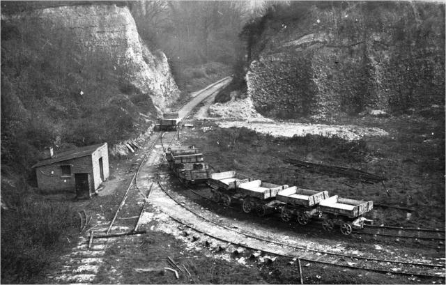
A useful dimension could be the driving wheel diameter (though there would be variations due to tyre wear) or, even better, the coupled wheelbase. I'm struggling to identify the builder of the loco in the picture, as I'm unable to find an exact match in the list of locos known to have worked for Grays Chalk Quarries. Does the photo show the worksplate more clearly? (Failing that, where did the photo come from?)
Ok, I've since "rediscovered" the thread in which the photo first appeared. Apparently it was taken in the Middlesbrough area and is similar, but is not one of the Grays Chalk Quarry locos.
Honestly if I had the engines' wheel diameter I would be very happy as all I'd need to do is scale it down and I can easily find scale ratios and convert them. But as far as I'm aware I have no source on that either. Infact that is why I want to figure the spacing of the sleepers in that photo so I have some form of measurement to go off of and make the scale down easier.
Also had a feeling it was a brother to the engine I'm using it as a reference to.
Circular, if you'll pardon the expression. It's the wheelbase the OP wants to determine!
Did I say that? *looks over first post* ah yes I did. Well in truth I may have been misleading there then. I'm really trying to find any thing in that photo that I can use as the proverbial yardstick and figure out it's scale. As mentioned above the buffers are far too low for the standard hight guideline to apply, The two crew members are of wildly different sizes in terms of tallness so the average hight of enginemen of the era can't be taken into acount (Again Sam told me the info of average hight of victorian era enginemen) and besides the tracks nothing is level with her like rolling stock or anything to have another reference point.
By the by I asked Sam about this too but once I convert all my drawings to a scale close to Gauge one/G scale I was thinking of posting them here for anyone to use. I think it be a nice way to give back to you guys for all the help. But I have no clue if there is a proper place on the forum to post scale drawings in or not and Sam said the same so if you like the idea point me to the place to post and once ready I'll be giving some resources out.
-
One other factor to consider are the north eastern engines that had a lower set of buffers closer together for dealing with chauldron wagons, what height and spacing were they, typically?
Wow just look at that coupling rod set up never seen the like in any other design.

-
Your picture has the loco standing on a turnout and thus the timbering will vary due to the need to support the common crossing with special chairs.
I looked at these images
http://gallery.nen.gov.uk/assets/0908/0000/0125/belmont_castle_mid.jpg
30ft panel -2ft (1ft each end) = 28ft / 11 gaps 12 sleepers = 2.54 or 2ft 6 1/2ins near enough. or may be
30ft panel -2ft (1ft each end)= 28ft / 10 gaps 11 sleepers = 2.8 or 2ft 9ins. closer examination on a larger screen I think it's only 10 per panel
Depending on location and time the track for the mainline will be the standard of the time, for other lesser lines the track will have been cascaded down from the mainline, at around 10 year intervals. lightly used sidings may have still been in pre group track even in BR times.
edit cos I forgot to add the extra sleeper.
Ok I'm still a bit slow minded at the moment (Just had three teeth pulled today) So I'll try to work the math out tomorrow. Hmm may I Pm you if I get stuck on calculating it my friend? Math was never my best subject as writing is my true calling alongside my Railway love of course.
Most BR plain line with 60ft rail and timber sleepers used 24 sleepers per rail length. With heavier axle loads in the late 60s (ish) and using concrete sleepers this was increased to 26 sleepers per 60ft. Not sure if that helps with scaling your little tank engine though. Your picture does look as if it has an overscale driver and an underscale 'lad' perched on the front buffer beam.
Edited to add: Would 'The Cronicles of Boulton's Sidings' give you any clues?
I need to look into that book honestly since it may give insight on my loco as well. Have to check Abesbooks. As for the info you gave that could be useful later on but again I'm not after BR, Highland, or Calidonian I'm looking for LMS spacing. I know BR took a lot of LMS' ideas and ran with them but we keep missing the station here.
-
Looking at photos of the chalk pit some of the track is laid on trunks. I would say 30 ft panels and 11 or 12 to the panel, guesstimating from the picture.
For the LMR, some more detail is required, as that will influence what sort of track would be in use. Mainline, secondary line, branch line etc.
Ok silly question how many feet between the visible chairs would you say the Chalk Pit had (Like in the above photo.) as I'd hope that you could say the chairs are centered on the sleepers and knowing their spacing would allow me to scale. Think of it like how most diagrams show buffer centers and distance between.
Also I did not say LMR. I already know the sizes of the two engines I wish to model from there. (Gazelle and Gordon respectively) I said LMS London, Midland and Scottish Railway from grouping till the days of BR. I'm not sure how to narrow it any further.


A Portuguese Streamliner
in Overseas Prototype
Posted
That would be wonderful my friend. No worries on the wait I can fully understand I just rearranged everything in my room to better suit me but I had to put a lot up as well so no rush. Thank you very very much.