


Dave Holt
-
Posts
1,069 -
Joined
-
Last visited
Content Type
Profiles
Forums
Blogs
Gallery
Events
Exhibition Layout Details
Store
Blog Comments posted by Dave Holt
-
-

James,
Great detailed shots - but I'm not convinced about your dughter's interst - in fact it looks like she'd prefer to watch the paint dry on the platform fence than admire the loco!
Dave.
-

Yes, Dave's kits always have beautiful etchings - so good in fact, one's almost tempted to just frame the etches and display them rather than build them! Instructions very comprehensice and thorough, with excellent diagrams. I've got three of his kits to build (eventually) - WD, B1 chassis and 9F chassis. I've been a bit put off starting for various reasons - not least that I'm not at all sure about tender mounted motors with shaft drive to the loco, as per Dave's design intent, and certainly the WD will require some fair modification to the fold-up inner frames to allow a loco mounted motor and gearbox.
Anyway, you J39 chassis looks very good, so far, and best of luck with it. Hopefully, you'll keep us updated with your progress.
Dave.
-

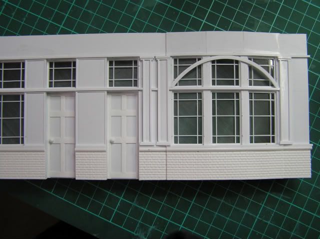
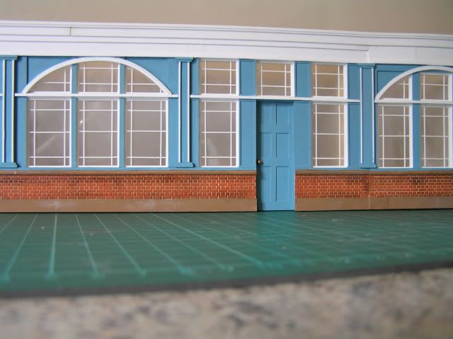
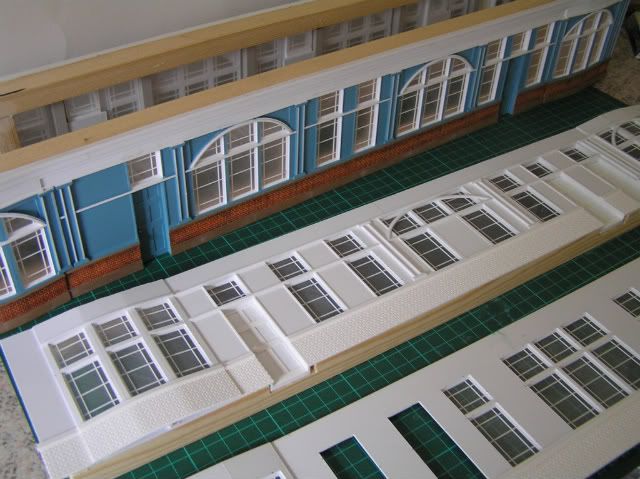
This does look a fantastic way to make large or complex buildings - and probably less risk of taking a slice off the tip of your thumb with a scalpel than cutting the parts out of plastic sheet. Not cheap, I imagine, plus the need for highly detailed CAD drawings?
Dave.
-

Thats the sort of thing I like to hear!
Will have a go at repositioning them this afternoon and see how I get on.
Have just tried to put some photos and notes on my blog, as promised - but I get an error message and it wont upload the photo files. I'll try again later. I have managed to scan in selected sections of the BR drawings showing the rear of the loco frames and a half-view of the rear of the cab support. You'll have to scale from the drawings based on the visible dimension(s).
Alternatively, I could just e-mail them to you, although file size might be a bit big?
Dave.
-
Look forward to seeing the sketch/photo, sounds like it will be very useful!
Just had another look at the truck frame,I have a feeling I have probably glued the Hornby sideframes in the wrong place! Starting to think that my original plan of trying to source a set of castings for the axlebox/springs and using them along with a modified comet west country etch might work better. No idea as to the accuracy of the Hornby cast frames...
Either way I will cut the frames back off tomorrow and see if I can realign them to get the right position.
Thankfully curve radius shouldn't be an issue (the layout is straight), though I think making them slightly narrower might be sensible just in case I make that continuous run expansion...
Actually, the Horby truck sides look very good to me. Perhaps re-positioning rather than replacement is the answer?
-
I'm following this thread with interest 'cause I've got one of these to do, myself.
Regarding the rear truck, it looks to me as if the rear of the truck is too low. Comparing the top of the pony-truck frame with the lower edge of the ash pan and the generator support vs a photo I took of Port LIne. Unfortunately, I don't know how to add photos to a comment or else I'd put it on for you to see.
As you say, on the real thing, the rear of the frames pass between the truck wheels, but in a model this might restrict side play unless you use prototypical curves - or narrow the frames.
The rear end of the truck should bear up against supports extending out from the frames at an angle. There is a pad at each outer corner, so the truck frame has three-point mounting so it can move sidewaysbut not up and down. Of course the axle is sprung so it goes up and down within the truck, to accommodate track irregularities. I replicated this arrangement on my Taw Valley model and it both works well and looks very convincing - no daylight visible through the truck area.
I actually have the full size BR drawings for the modified MN frames & cab support but they're far too large to scan (generally 1.5"/foot scale) and I'm not keen to send them through the post (cast & risk of loss). I'll try and dig them out and sketch some details. The underside of the rear frames is 0.67 mm below thr driving wheel centre line and the bearing brackets 2.77 mm below. Allowinf say 1.5 for the bearing pads, that would put the top of the rear of the truck 4.27 mm below dring wheel centres or about 8 mm above rail.
I'll create an entry in my blog with the photo and some sketches in the next few days - but with the current problems you might have to dig a bit to find it!
Good luck.
Dave.
-
Thanks both for the comments and advice. I haven't installed anything yet - just planning, and I suppose my idea of omega loops was based on seeing other layouts which used solenoids for point operation. I appreciate that the output throw of the Tortoise is adjustable but had rather overlooked the flexibility of the steel operating wire to give the effect I need.
So, thanks again for putting my thoughts in order.
Regards,
Dave.
-
Corgi and EFE produce suitable North Western Road Car double deck buses for the routes 13 & 14 that pass Delph Station, but you will be struggling for an Oldham Corporation bus. There is a Manchester Crossley DD42 but its not appropriate.
Your layout is going to look the bees knees particularly in P4 as well.
I wonder what your reaction will be to the news that I've just sent off a CAD drawing for the LNWR D333 suburban brake third. Always promised myself one.
Larry
Larry,
Good choice of prototype; I think they were fairly common in our area in the 1950's. If you recall, I built one from a kit but had to hack the brake compartment end about to get two larger windows. I'll pop a couple of photos up separately (don't know how to add them to a reply/comment!)
Dave.
-
Robin,
This looks a very exciting and ambitious project - I very much look forward to following progress. Eventual scope for visiting locos?
I can only agree with Peter's earlier comments. The extent of trackwork makes my layout seem very simple and straight-forward. Best of luck.
As a matter of interest, are you planning to make the series of small turntables near the workshops functional?
Regards,
Dave.
-
Can I presume from the lower level you will also be modelling the road that passes the coal shutes and paralleles the branch? If so that should give the layout an added dimension as well as extra depth. It is something I have been considering when Mk.III Greenfield commences...

Larry,
Yes. I'm including the road along the front of the station area as it sweeps down from by the station masters house, past the goods shed and round past the drops. It then gets quite close to the railway with a high stone retaining wall/butress at the nearest point. Also the river tame at a lower level still comes in one a sharp bend and then off again at that location. As you say, this will hopefully give some width and depth and help put the railway in it's proper setting. The lowest part of the road is a scale 20 feet below the railway and the river 25 feet. (I got these elevations from a plan which I seem to have lost since.)
I think I've mentioned before that I'm disguising the exit into the fiddle yard by moving a cottage group and back lane up and over the railway from Dobcross - as shown in your wonderful Delph book.
Regards,
Dave.
-
Try not to hurry Bill into doing it, otherwise you may find mistakes!
 I seem to remember that he seems to do a fair amount of design work for Comet, and is one of the reasons why their chassis range is being progressively upgraded to "modern" specification.
I think the only part of the fret that you can't use on, or adapt for, the MN is the rear section of the coupling rods. Everything else is up for grabs.
Dave: ever tried converting the Dapol plastic Light Pacific kit back to an original Merchant Navy?
Requires lots of plastic, solvent, and swearing!No! Can't stand the originals - what have I said - bound to get well deserved abuse for such a provocative statement? Seriously, as a professional mechanical engineer, I have severe reservations about aspects of the Mr Bulleid's designs and am fully of the opinion that modification was the best solution - I understand that total scrapping was the alternative! Another reason is that I find the prospect of the inside valve gear and oil bath a bit daunting in 4 mm, as well.
Dave.
-
For coupling rods and valve gear, you've mentioned the Bill B etch. I've got one of these etches with a view to converting a Hornby but haven't done anything yet (tried to talk Bill into doing a full etched chassis....maybe one of his easy fold up jobbies...?). Anyway, as Horsetan has said, Bulleids have quite narrow frames, so not too much packing on the outside of the Hornby unit.
I've found the Comet etches very useful. They do a suitable front bogie and their WC valve gaer should contain useable parts as the actual valve gear is very similat indeed between the MN and light pacifics, except for the coupling rods and the expansion link support bracket - which is a cosmetic issue on a 4 mm model, I would suggest.
Best of luck with it and keep us updated with progress as I've got both a MN and light pacific Hornby to P4, eventually - will need them both for Delph!!!!!!
Regards,
Dave.
-
That's a frightening curve off into the mill yard, just like the real thing. Must have made the loco's flanges complain a bit!

Larry
Yes. it is rather sharpe. One or two people have questioned whether it is viable in P4, but it is as near scale as we (Tony Wilkins, actually) could get using Templot. I've successfully pushed my WD 2-8-0, tender first, propelling a couple of 16T minerals round by hand. No problems (there's gauge widening and continuous check rail to help) but it might be different under power. The Ivatt/BR class 2 tanks have a nice, short coupled wheelbase, so they might be OK. Lancky class 27 0-6-0's are probably what were used in real life?
Dave.
-
We took such design aspects as granted, Dave....

Are you fishplating 'as you go' (Exacto) or later?
All fishplates will be purely cosmetic and I plan to add them later, It looks like if the Exacto one are cut in half thet can be fitted where there are rail gaps. Otherwise I think etched brass ones soldered or glued in place should do.
Dave.
-
No-one's commented on the red hatched areas visible on the underlay. In case you're wondering - they mark the position of obstructions under the boards (Tortoise motor mounting plates, etc.) to be avoided when fitting droppers to the track.
Dave.
-
Waay to go, Dave, but I hope you've got the height of the flexi and that ply'n'rivet aligned...
Good point. According to my measurements there's a 0.1 mm difference in height, with the flexi-track being the higher. You may notice the strips of masking tape across the formation in some places. This is where ply pointwork meets plastic plain track and by chance is 0.1 mm thick. Hopefully this will overcome the problem and result in a nice smooth transition. (I've checked with some loose track and it does appear to work.)
Dave.
-
Your P4 track looks very good Dave. But I'm more interested in those little pots you have used for holding the track down. I use them for paint indoors so if you have a couple spare, please bring them with you next time!
Coach, I also use them for paint, but I'll see if there's a few spare!
-

Peter,
All superb work and a pleasure to see. It's a good job there isn't the need for a coaling plant at Delph!
I'm intigued to see you have modelled Spratton (small village in Northamptonshire) signal box - hardly the centre of the universe - although it's the centre of MY universe, 'cause that's where I met and married mywife.
Look forward to more stunning architectural models. Keep 'em coming.
Dave.
-
Test:
Berwick on Tweed 7mm.
Hi, Gravy! Welcome to the new version of RMweb. Look forward to following this blog as you add more content. Are you going to put Delph stuff on here rather than on Coach's forum thread?
Cheers,
Dave.
-
 1
1
-


More J39 progress
in Fen End Pit's Blog
A blog by Fen End Pit in RMweb Blogs
Posted
Yes, having the axlebox flange on the outside only will prevent the use of springs to hold the horn-guides against the frames (my normal method). You might be able to get away without springs and keep the axleboxes in place with Blutac or there is high temperature adhesive tape available which might be useful to hold the horn-guides in place till tack soldered. Finally, a thought which will probably get me drummed out of the loco builders guild - if you turn the axleboxes upside down (not back-to-front), the flanges will be on the inside, allowing the normal assembly method. Turning the boxes this way will not affect the longitudinal position of the holes in case of any eccentricity in the fore-aft direction. Please don't hit me, it's just an idea!
Chassis coming along nicely, by the way.
Dave.