


CF MRC
-
Posts
2,031 -
Joined
-
Last visited
Content Type
Profiles
Forums
Blogs
Gallery
Events
Exhibition Layout Details
Store
Posts posted by CF MRC
-
-
Mick Nicholson has sent me this fascinating MRN article from 1935.

For our younger readers, here is a comparison picture of a current £1 coin compared to the half-crown (12.5p in ‘new’ money).
A little bit bigger than T gauge, but a very, very small prototype.
Tim
-
 15
15
-
 2
2
-
-
- Popular Post
- Popular Post
After a bit of fiddling there is now a working somersault signal on the Belle Isle Down signal bridge on CF. There will be another arm working (these two signal a conflicting route) and the other 6-8 can be in fixed positions. I’ll try and take construction photos when the next one is being made.
The signal arm was chemically blackened to prevent it being soldered solid.
The video shows it simply being pulled on its connecting rodding. There will need to be some cranks and linkages across the bridge to activate it.
Tim-
11
-
10
-
 3
3
-
13 hours ago, MarshLane said:
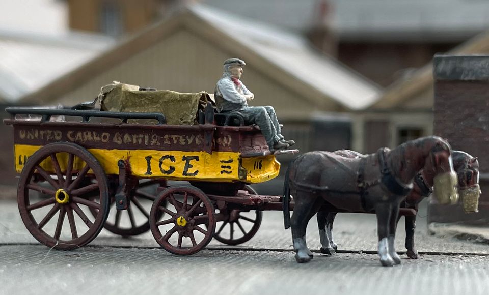
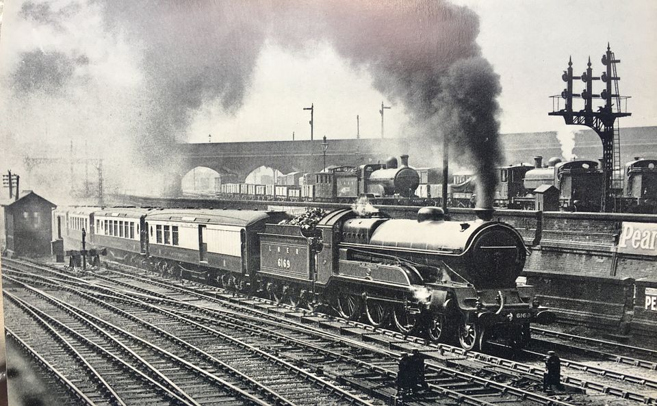
The whole area around King's Cross, KX Goods and Regents Canal is a fascinating one as this image shows. Thanks for reposting it. Great to see.
Well worth visit if you’re in the area.
https://www.canalmuseum.org.ukThe ice wells were the source of information for our cart.
Tim
-
11
-
 1
1
-
1
-
-
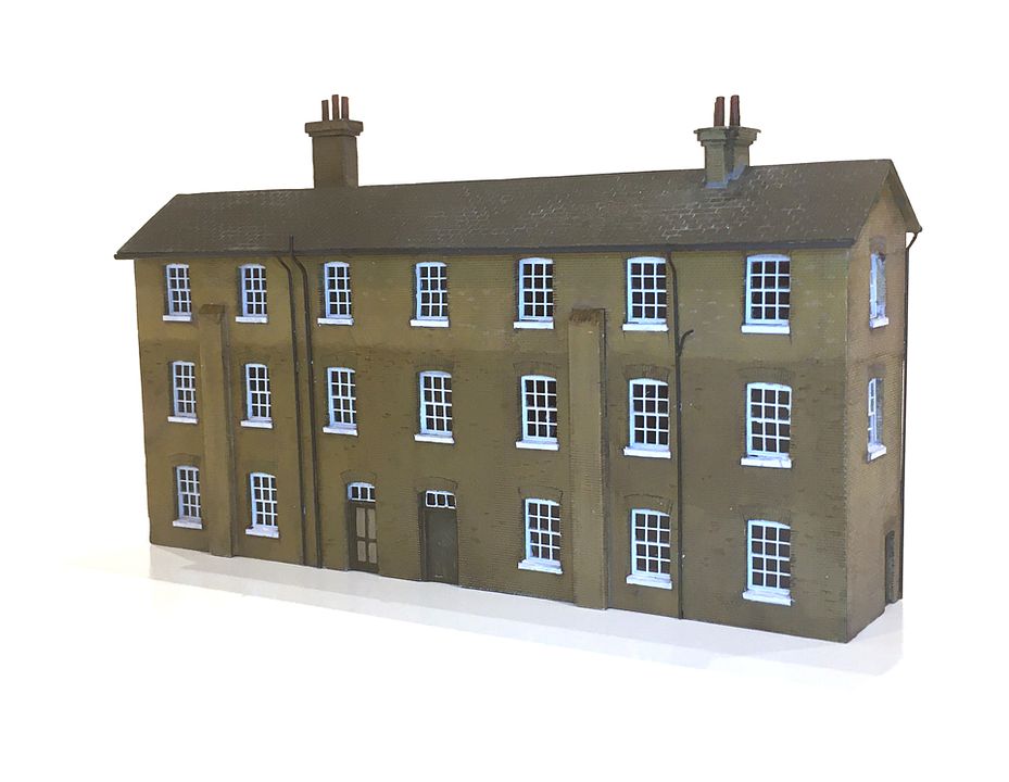
We stopped at the Kilner Co offices, which received a third storey by the time we modelled them. The model was made by Tom Knapp in Hawaii.
The south end operator is effectively sitting in the Regents canal.
Tim
-
12
-
3
-
-
Bit of a long-shot, but does anyone have the contact details for Tony Dyer, Frank Dyer’s son (Borchester etc.)? We have had an enquiry at the MRC from someone trying to re-establish contact.
Tim
-
- Popular Post
- Popular Post
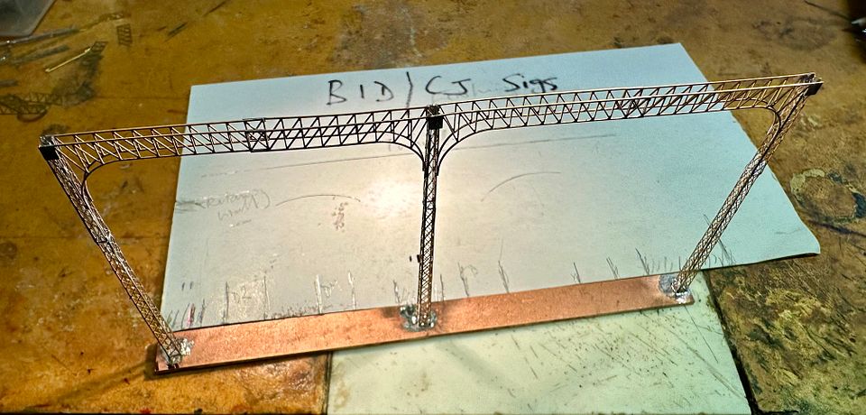
Some more progress on the signal gantry at Gasworks Tunnel.
The dolls were filed up very quickly from some 2mm square brass. I use very sharp, coarse, Vallorbe files to shift metal and then dress with finer grades.
The bridge is only partly planked, with over half open at the top. This was not catered for in the etch and so it required the herringbone bracing to be made. This was bent up from brass wire.
After bending, the wire was flattened in a vice and soldered in place one node at a time. It has strengthened the structure rather well, as have the lower footboards for the signal dolls.
Should add a bit of interest in the ‘trough’.Tim
-
18
-
15
-
1
-
1 hour ago, Caley Jim said:
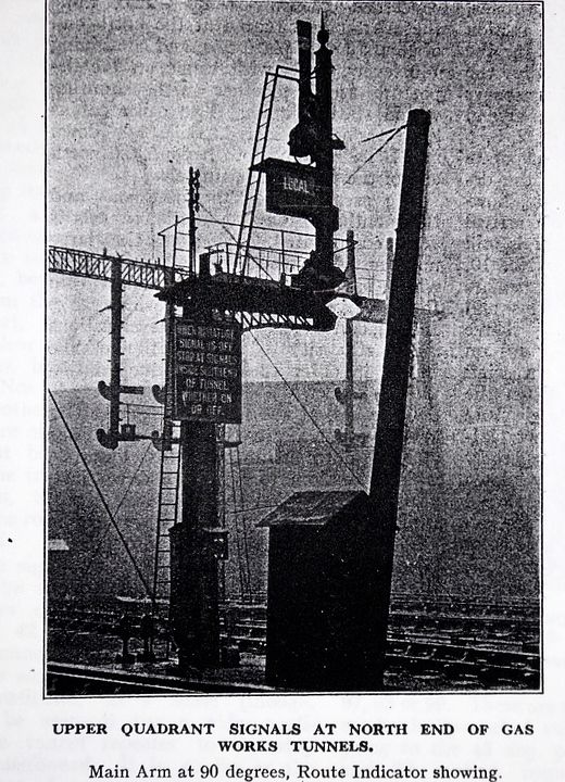
Can I ask why the gantry was so high and the signals suspended so far down from it?
Jim
It’s presumably to give sighting from the tunnel, Jim. They do seem quite extreme though. Maintaining them would have been a bit of a game.
Replying to David, we always use aerial photographs - originally ‘proper’ images in the 1980s. There are none of this area with decent resolution at this period. (1920s). There is nowadays a massive resource on-line which can be usefully image manipulated to yield lots of information.
Tim
-
1
-
2
-
-
Thanks for that David. They probably would have remained in GNR condition as the gantry was taken out of service in 1932 with the KX re-signalling. There is another signal in the vicinity which is rather fun.
The image also shows step pegs on the nearer dolls and only partial railing on the gantry at high level. The more you look the more you see…
Tim
-
10
-
-
- Popular Post
- Popular Post
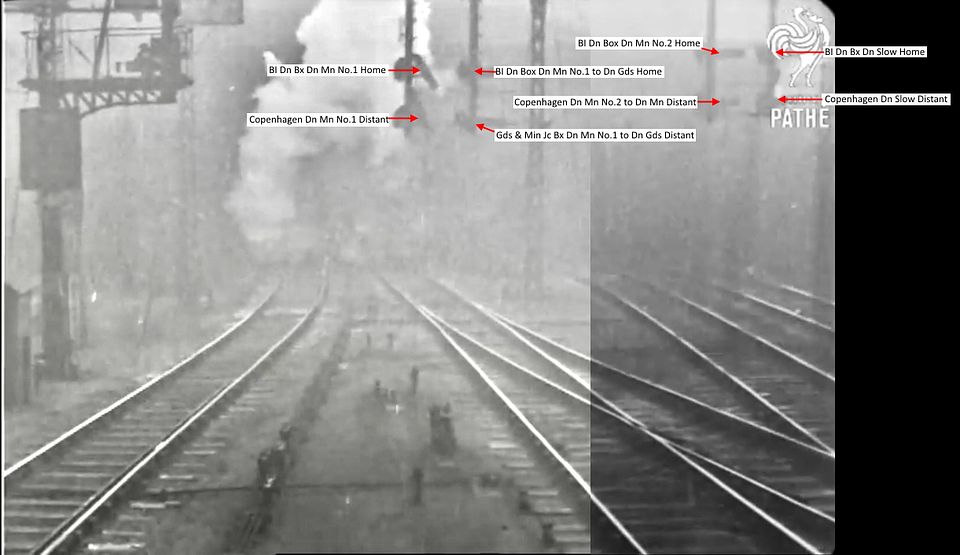
Now the fun and games can start.
This is the beginning of the four doll gantry at the north end of Gasworks Tunnel on the down lines.
There aren’t any decent close up photos of it, but these are the arms that will be modelled. At least two of them should probably work sometime, as they signal a conflicting route, but we’ll see.
Maybe we should just put a steam generator in the tunnels, so they’re hidden, a bit…
Tim
-
20
-
1
-
In fact, the loco is currently being charged-up to see how it performs (I will probably be in touch with Giles Favell to compare notes on ‘tuning’.) It really is a pretty engine and deserves to get the Joy valve gear made and finished: trouble is there is a 2mm loco also in the works at the moment…
On the layout front, I am about to acquire four superb baseboards made by the late Mike Randall for an erstwhile 2mm scale layout. These will fit Lynton perfectly, but the 2mm stuff on top will need removing and then tidying up the box beam frames. The new layout will be a fitting tribute to Mike, who was responsible for the CF structural build.
The plan is well sorted and the turnouts were made by Keith Armes (one of his last projects). I have just ordered a stock of sleepers from Marcway for the remaining plain track (i.e. most of it).
One of the biggest psychological stumbling blocks was the station and goods shed tiled rooves. I am using the Outback Models kits as a basis, and the printed tiles just don’t work - I can get a good stone effect, but the tiles need more work. I think I now have a solution from Scale Model Scenery.
It’s good to have lots of projects…
Tim-
2
-
-
‘Perchance it “is not dead but sleepeth”.’
Tim
-
2
-
-
The ECMs, I recall, had three settings of feedback on them. Even so, they weren’t very kind to Graham Farish motors (which were in the majority of mechanisms in the early days). The mechanisms were slowly replaced and all our locos now have coreless motors. The ECMs were replaced by Pentrollers in the early ‘90s which Stewart Hine developed for Pendon. These also had three feedback settings depending on the motors in use: we always used the coreless settings. These have been replaced on the mainlines by PICtrollers in the last ten years, which automatically sense the motor type and adjust feedback accordingly.
Tim
-
3
-
3
-
-
On 15/04/2024 at 11:19, Captain Kernow said:
Would you mind saying what kind of controller you use with the coreless motors, please?
Thanks.
These were originally controlled with ECMs running on a low feedback setting (not ideal for any N gauge motors) then with Pentrollers, when they became available, and more recently PICtrollers. For testing locos I use a straight DC controller.
Tim
-
3
-
 1
1
-
2
-
-
I’m looking forward to the N gauge Buckjumper…! I have been using coreless motors for 45years, with very, very few failures in heavy use. They easily outperform cored equivalents.
Tim
-
4
-
 1
1
-
1
-
-
That is a very pretty little engine!
Tim
-
1
-
-
“Perhaps we can pool them together and run the 'Ashburton Grove Pullman' on Copenhagen Fields...”
We used to run one when the layout ran BR period stuff in the early days.Tim
-
8 hours ago, Matt.S. said:
Is it a BDA?
Nope, they’re at 64 Wimpole St.
Tim
-
 8
8
-
-
- Popular Post
- Popular Post
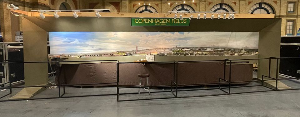
Mike Randall, a major contributor to the construction of Luton Hoo and Copenhagen Fields, has died from complications arising from his cancer treatment. Mike was well known in 2mm scale modelling circles and was responsible for all the plywood engineering that makes up Copenhagen Fields, with perhaps the most impressive feature being the 22’ span proscenium arch that takes the layout lighting and frames the scene.
Mike was a major contributor to numerous MRC projects and pursued multiple interests outside of railway modelling with never diminishing vigour. He will be greatly missed by us all in the Model Railway Club, having given a great deal over the last 40+ years, based of his encyclopaedic knowledge and skills in timber and building construction.
Tim Watson
-
1
-
 29
29
-
- Popular Post
- Popular Post
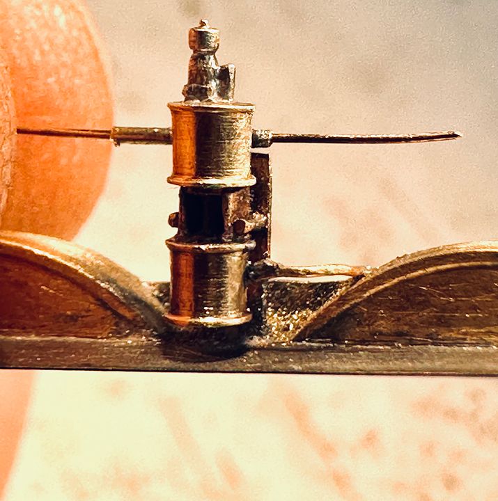
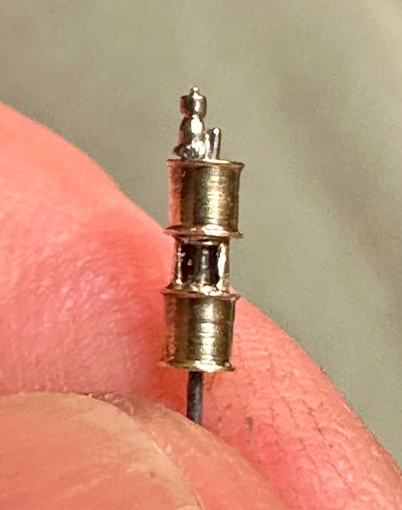
I couldn’t really resist continuing with the Westinghouse pump, so it now has the compressed air pipe fitted and the basic fittings for the steam feed and exhaust.
The feed pipe fitting was made from some 0.5mm OD brass pipe, soldered into the groove cut in to the back of the steam cylinder. This did not have a large enough bore and so it was reamed out using an 06 endodontic file. These are the smallest used in root canal treatments and are made from nickel titanium alloy. The size represents 0.06mm diameter measured 1mm from the tip.
The video clip shows it in action.
The regulator on the LHS is next to be added and the pipe work can be seen here as a piece of 33swg phosphor bronze wire.
Having this running plate unit as a separate sub-assembly has made it much easier to work on. Apologies if this post relives dental memories for some!
Tim
-
14
-
11
-
3
-
- Popular Post
- Popular Post
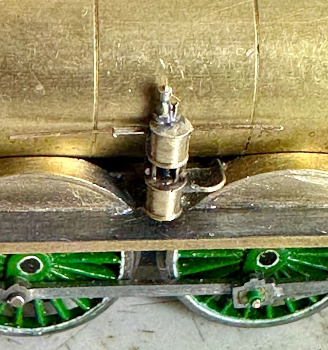
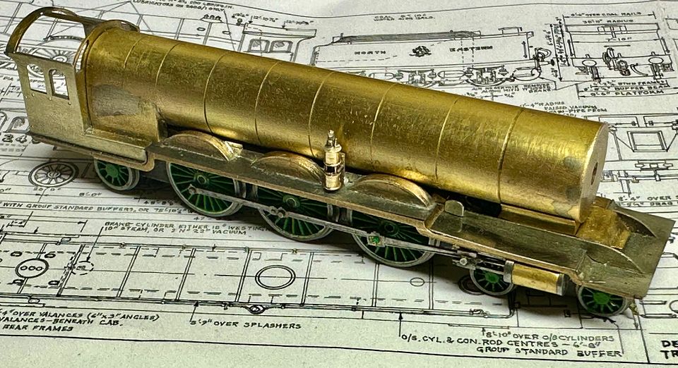
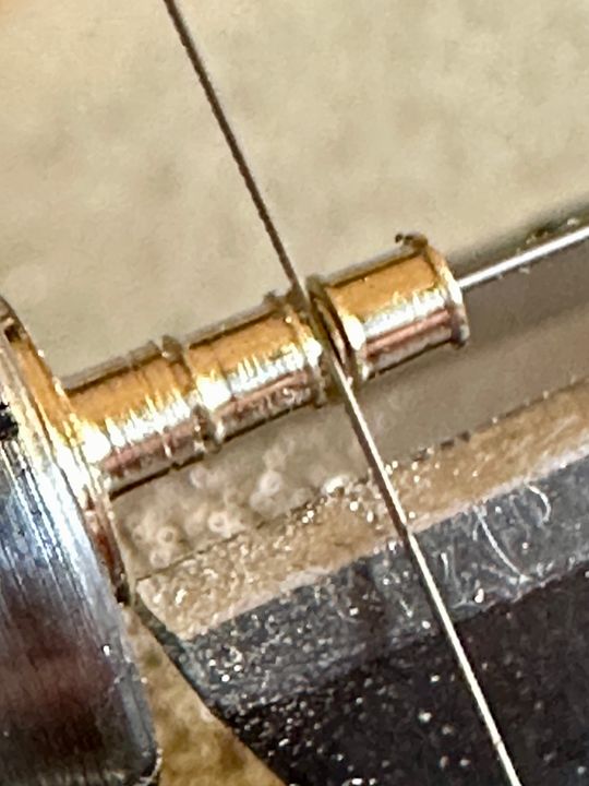
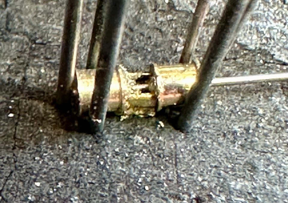
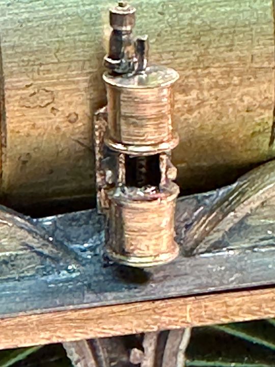
After a few hours of fiddling, the basics of the Westinghouse pump on 2400 are now complete. The steam supply & exhaust plumbing will probably be made later, the air delivery pipe rather sooner.
A 2.3mm diameter blank for the cylinders was turned and centre drilled 0.4mm over 5mm depth. Drilling such a deep hole is taken very carefully, with many clearance removals, aided by RTD cutting fluid, and sharp TC drills.
The blank was then finish turned with a graver, giving the raised ends to the cylinders. A piercing saw was used to separate the two cylinders, also making the stuffing box at each end.
A conventional 0.4mm diameter steel drill shank was used to align the cylinders and a U shaped piece of brass (box section 1.6mm square with a side removed) inserted between the two cylinders - this represents the casting that holds them together on the real thing. The assembly was anointed with silver solder paste and pinned into a stable relationship with old drill shanks thrust into the charcoal block. The whole assembly was gently brought up to red heat for the solder to flash. On a very fine and small component such as this I turn off the workbench lighting so that I can gauge the temperature more easily.
After pickling in citric acid, a few holes were drilled in the cylinders for the shuttle valve and oiler on the top, compressed air outlet pipe and a slot cut on the back for the steam inlet and exhaust pipes. The drill shank is a very useful handle to hold this rather titchy component.
The mounting bracket on the running plate had been fitted previously (with two holes drilled in it) and this was augmented by a couple of pieces of brass wire which were threaded as one U shaped staple from behind and soldered in place. The excess wire was cut off and dressed in front and behind to neaten them up.
These two pegs represent some substantial brass bolts in this area and made it easy to locate the pump for soldering to the bracket: the drill shank had previously been sliced off with a diamond disc. Having the main pump silver soldered ensured that it didn’t fall apart when attaching it to the locomotive.
(photo courtesy Owen Chapman)
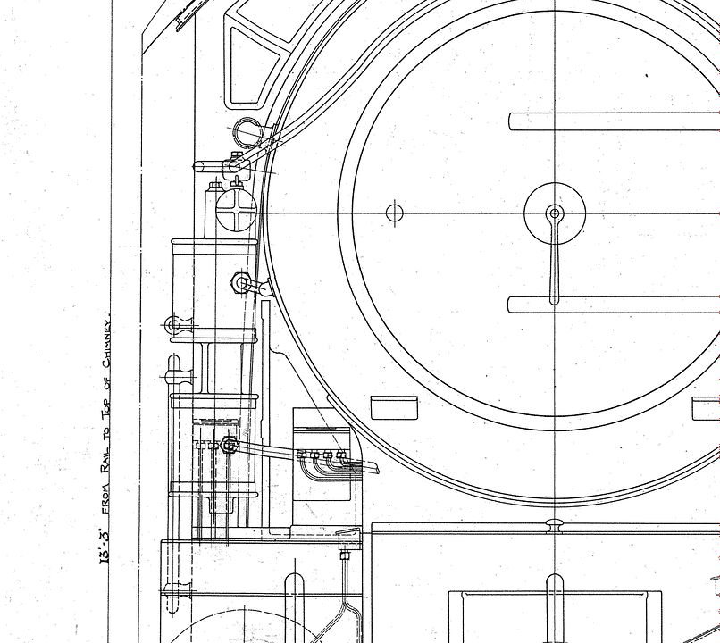
The final result needs to fit very close to the boiler as the hand rail takes a detour round the top of it! The extra bits for the pump will be made when the associated plumbing is fitted.
The piston is scarcely visible - like the real thing - but at least I know it’s there. The Association makes a 3DP version of this which is very fine, but I prefer turned metal in this situation. The 3D metal print looks a bit ‘hairy’. Quite crazy really, as the whole thing is only 6mm tall.
Tim
-
10
-
24
-
3
-
Deleted
-
1
-
1
-
-
- Popular Post
- Popular Post
Some more progress on the Skittle Alley today.
The representation of the prototype frames between the splashers have now been fitted. These were made by soldering a strip along the back of the splashers and then cutting out the unwanted bits with a piercing saw; finally tidying up with a bur, so saving fiddling with small pieces.
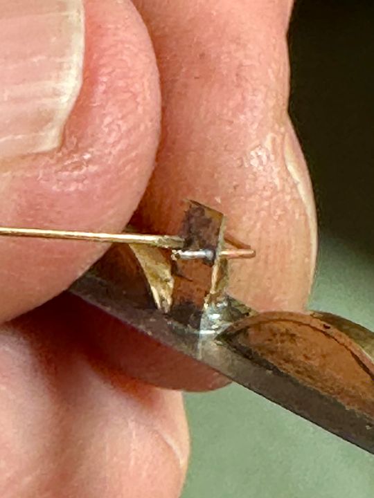
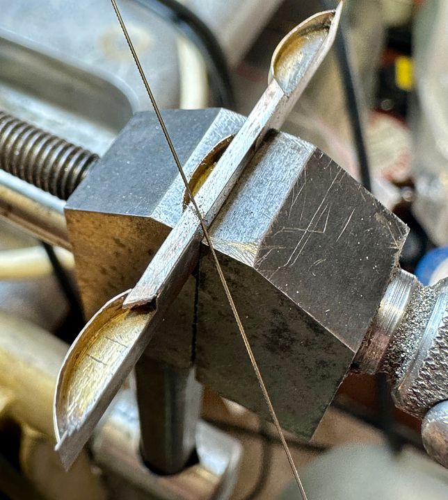
The next item was the bracket for the Westinghouse pump. This was a very substantial casting in real life.
The next photo is of a prototype made with a (too) small brass T section. The end piece is folded over and the junction with the upright pillar flooded with silver solder paste and gently heated to flash into the crack, so making a strong assembly.
The definitive bracket was made from 3mm brass T section, filed down to size (approx. 2mm wide) with the foot silver soldered in place. A long handle was retained for holding during construction and positioning the bracket on the running plate whilst soldering: I use this technique a great deal for stabilising small pieces during assembly.
The top had been partially cut through so that it simply needed twisting to remove the handle.
I have a cunning plan for making the pump…
Tim
-
18
-
12
-
- Popular Post
- Popular Post
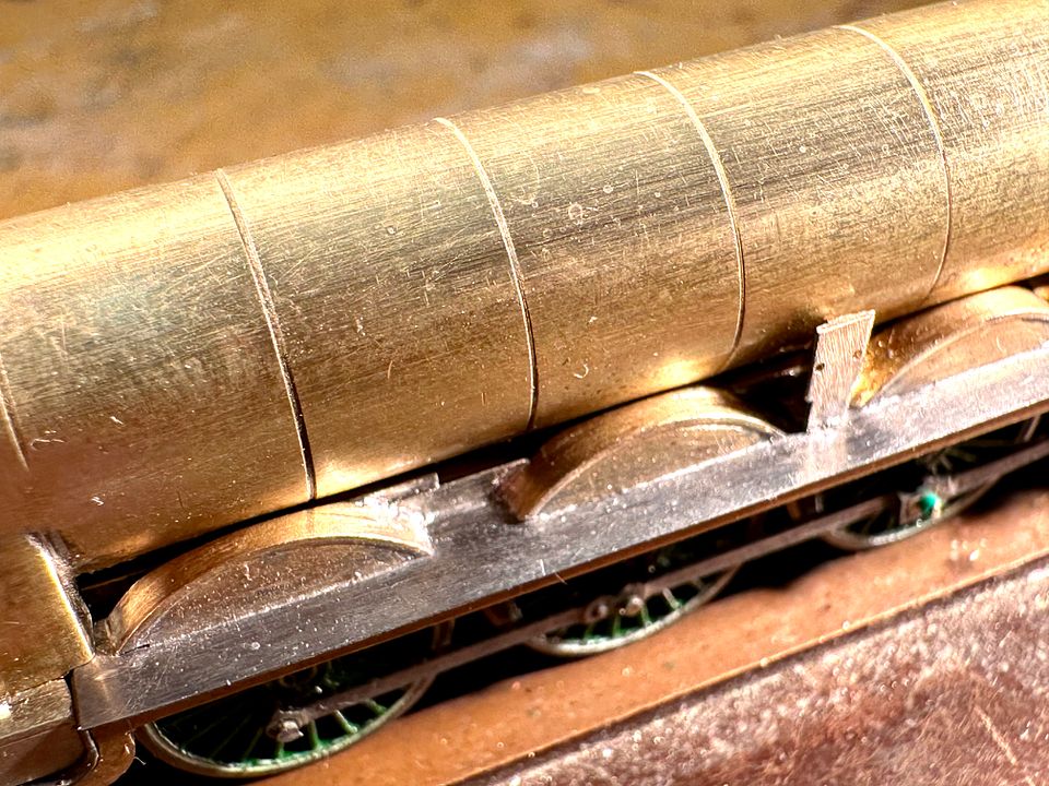
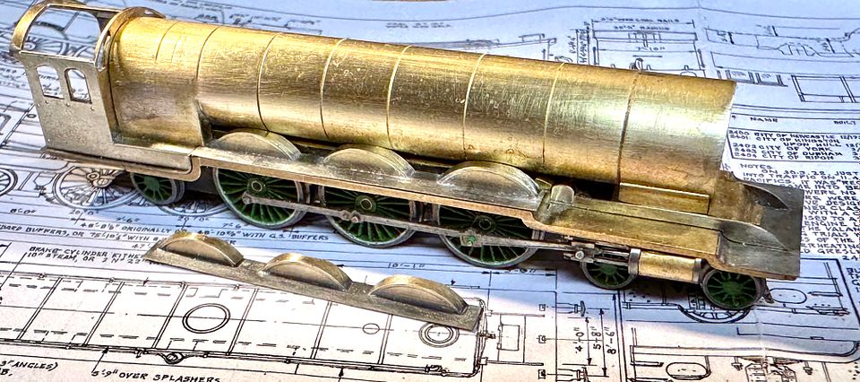
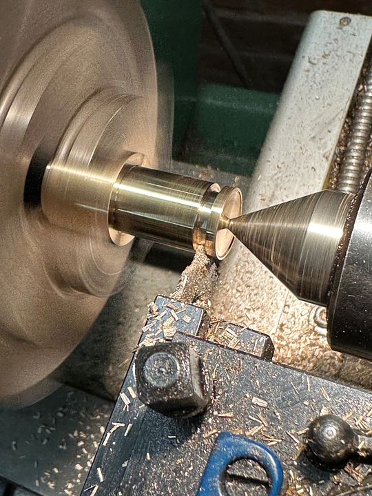
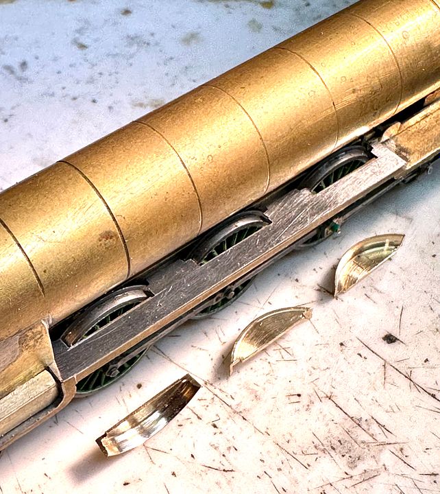
I have been working on the splashers for the Raven NER 4-6-2 class over the last few days. She’s beginning to look a bit more racey, with the wheels covered in a bit.
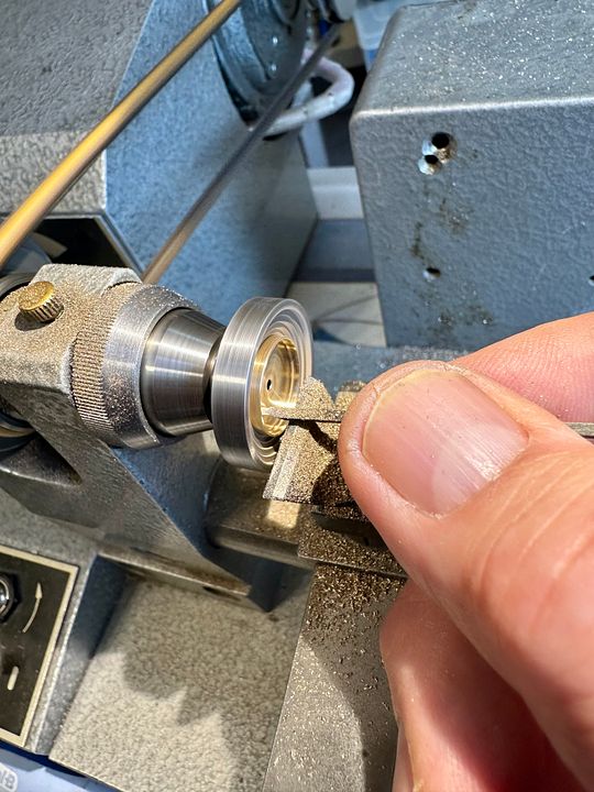
The brass disc blanks were turned from a lump of brass in the Myford 254. The front face of the splashers, including the brass rim was finshed on this lathe as can be seen:
Five discs were made and parted off. One as a prototype and two were used.
The discs were mounted in a step collet on the watch maker’s lathe and hand finish-turned using a graver. Important to note that the graver is held with a pen like grip so that should it ‘catch’ then it flies from your grip, not through your hand.
The thickness of the splashers was checked using a thickness gauge, which Jim will recognise.
Once happy with the proportions the splashers were cut off as chord segments with a piercing saw. The tops of the running plates were made from 5thou steel, with suitable clearance notched for the wheels. The splashers were rebated at each end so as to locate on the steel when soldering into place.
The engine has a Westinghouse pump on the RHS: that should be fun…
Tim
-
9
-
23
-
5
-
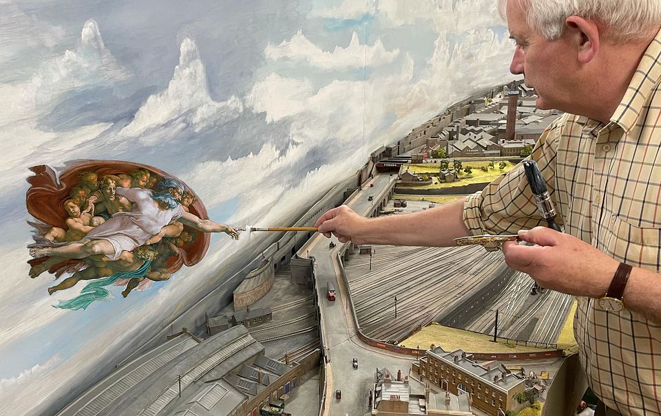
Nah… Go for broke, get those clouds in!
Tim
-
2
-
1
-
7
-


Copenhagen Fields
in 2mm Finescale
Posted
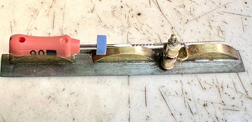
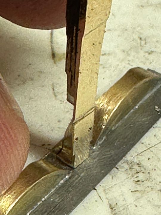
As mentioned previously, I have taken some photos of the fabrication of the second somersault signal. The main components come from MSE (Wizard Models). The etch doesn’t quite manage the holes for the operating linkage so these were drilled out 0.2mm for the linkage and 0.3mm for the pivot.

The signal arm bracket requires a bit of work to help locate it on the doll. Working on the principle that it easier to drill a long 0.5mm hole through the doll rather than 0.3mm, the bracket was bushed with a length of Albion Alloys brass tube, OD 0.5mm, ID 0.3mm. This then acts as the pivot for the spectacle and back blind. The far end of the bracket also needed building out with a washer. These components were located in a vermiculite block using pins and soldered together.

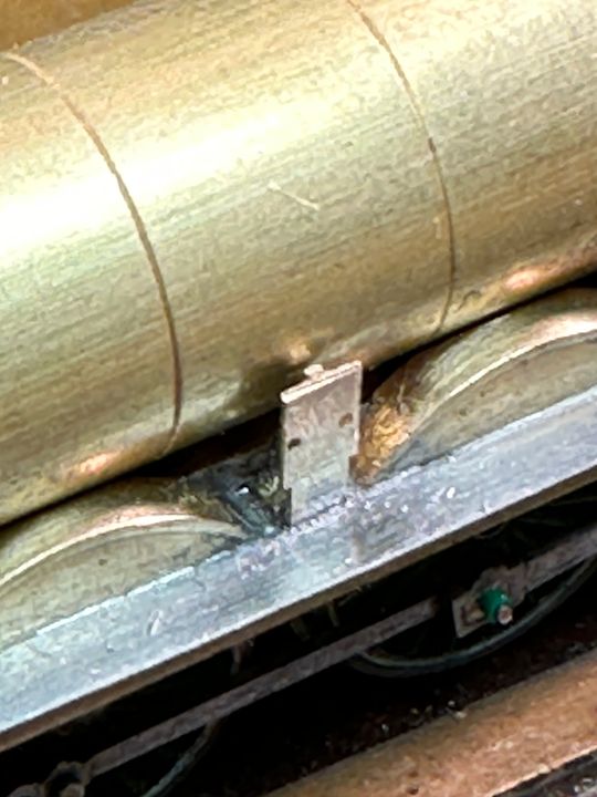
The pivot bush makes it easy to locate the bracket on the doll.
Once in place, the front face of the pivot on the bracket was filed flush, as the spectacle has to work behind the signal arm.
The spectacle was soldered to some 0.3mm brass rod and filed flush. It was then linked up with a length of thin phosphor bronze wire through the 0.2mm diameter hole in the actuator arm.
The PB linkage was bent forward in the position of the application point on the signal arm.
The three components were then chemically blacked to prevent soldering (but scraped off where the collars / back blind needed to be soldered on.
Once on the bracket the pivot pins were retained with a collar and the back blind, which was also used to connect the drive rod.
This arm doesn’t quite pivot as vertically as the other one: the linkage length and pivot relationship is critical, but it is within the normal range. I am jolly glad that I don’t have any more to make as working arms on this signal bridge as my patience and eyes are pretty well exhausted.
Tim