


CF MRC
-
Posts
2,032 -
Joined
-
Last visited
Content Type
Profiles
Forums
Blogs
Gallery
Events
Exhibition Layout Details
Store
Posts posted by CF MRC
-
-
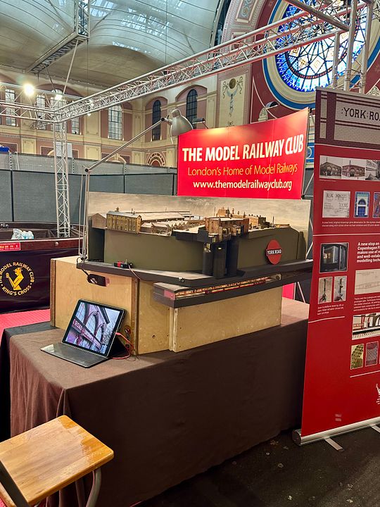
I had a really fun time at Ally Pally with the YR diorama last weekend. It was great to have visitors being able to get really close to the model to actually see it! The interest in underground modelling is clearly developing and I spent some considerable time showing individuals historical images and also construction images using the iPad. These have now been ordered into logical albums, which will also simplify giving talks.

Tim
-
 6
6
-
-
- Popular Post
- Popular Post
I had a really fun time at Ally Pally with the YR diorama last weekend. It was great to have visitors being able to get really close to the model to actually see it! The interest in underground modelling is clearly developing and I spent some considerable time showing individuals historical images and also construction images using the iPad. These have now been ordered into logical albums, which will also simplify giving talks.
Back to the Skittle Alley.
Tim
-
19
-
 1
1
-
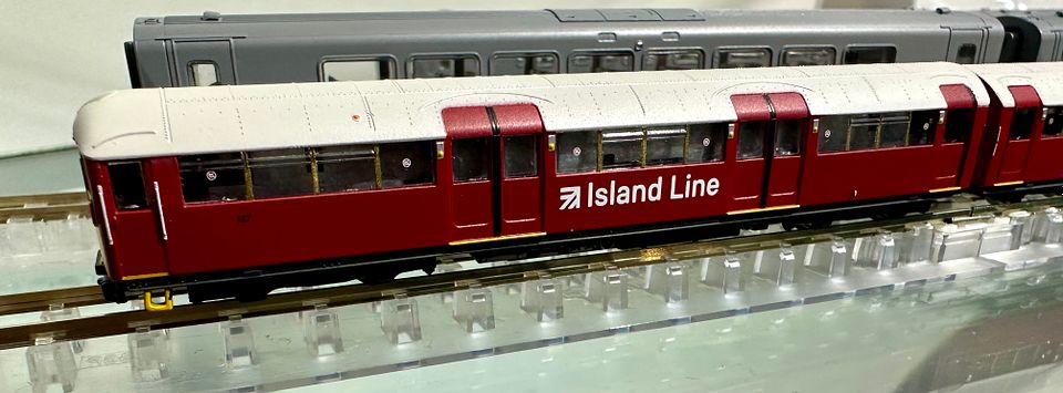
I was fortunate to get a picture of the paint sample ‘38 stock, looking very sharp and smart.
Evidently, the non-motor cars are going to have some extra weight incorporated to improve running. I think these are going to be immensely popular - there is a tremendous amount of interest in the underground, as I found out this weekend at AP.
Tim
-
9
-
3
-
 4
4
-
 2
2
-
-
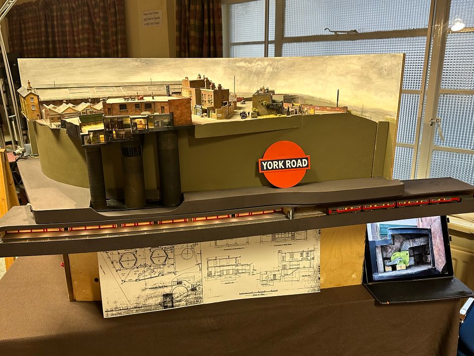
York Road all set up on the MRC stand 47.
Lovely view of the rose window.
Tim
-
4
-
-
- Popular Post
- Popular Post
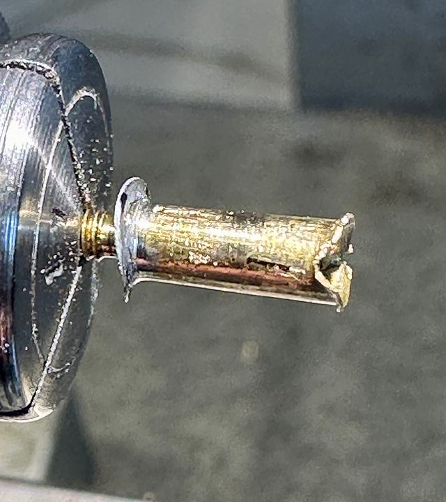
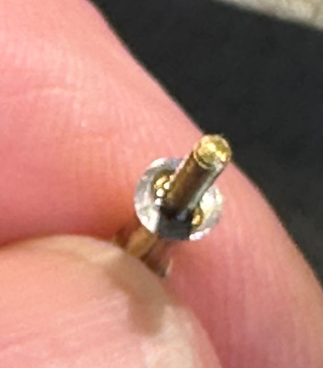
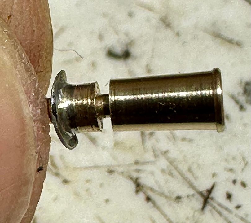
One of the Grove’s locos had obviously sustained a fall and had a badly mangled chimney.
This has been screwed on to the smokebox and had a made-up saddle, with a filet of solder around the base. The brass chimney did, however contact the smokebox. Fortunately, it was easily removed from the loco and a brass dowel plug turned to fit from the base up to half the height of the chimney: it was then Loctited in place.
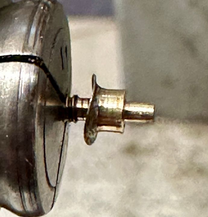
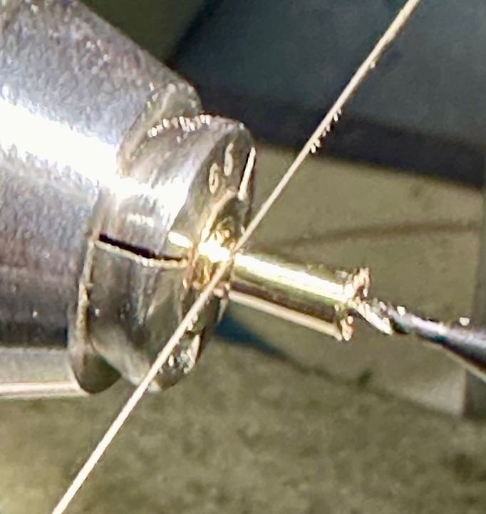
The chimney top was then parted off from the base, but retaining the plug. I often use a piercing saw blade for parting off, these days. It is very precise, and makes very little kerf.
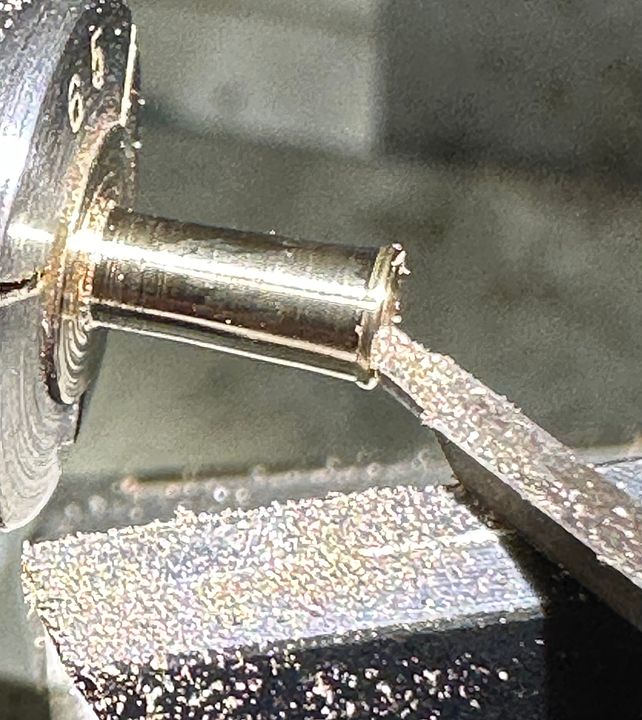
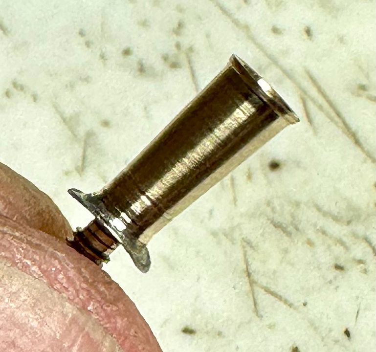
A replacement top section was then turned up with a central hole to fit the plug. A graver was used for fine turning.
This was then parted off and offered up to the base.
Once Loctited in place, the chimney was finish-turned to the same dimensions as the original.
The chimney was chemically blacked, Araldited in position and painted satin black to match the rest of the engine,
Quite a long winded description of a fairly challenging little job. Should be ready for Ally Pally on Saturday.
Tim
-
18
-
1
-
 12
12
-
 3
3
-
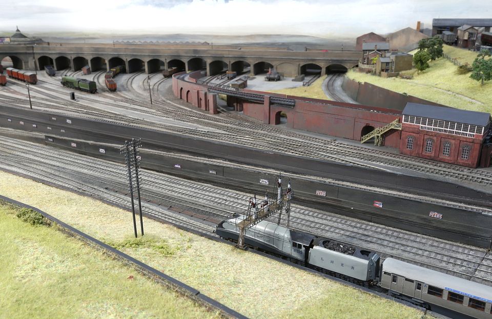
York Road diorama will be in attendance on the MRC stand (not listed in layouts).
Also flying the 2mm Finescale flag will be the Rydes Vale goods yard and engine shed, again on the MRC demonstration stand. This is the original 2mm fine scale layout from the mid 1960s. It is the first time it will have been seen in public for many years.
Tim
-
10
-
1
-
-
Maybe ‘trade’ has been good Jim so she’s gone for gold…
Tim
-
1
-
1
-
-
34 minutes ago, St Enodoc said:
That's all very well but how are her teeth?????
Vulcanite with porcelain gnashers.
Tim
-
1
-
2
-
 2
2
-
-
They are exceedingly long. Take a look at the turnout that starts under Silver Fox.
Tim
-
11
-
-
- Popular Post
- Popular Post
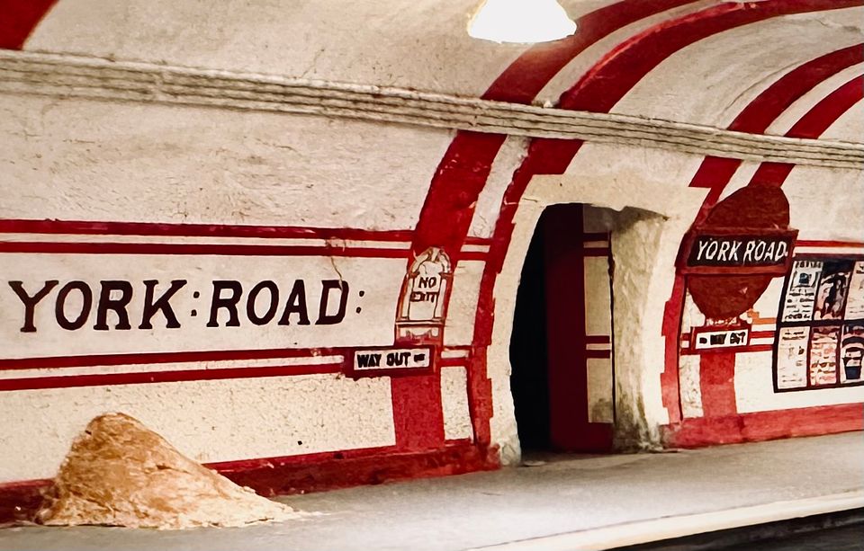
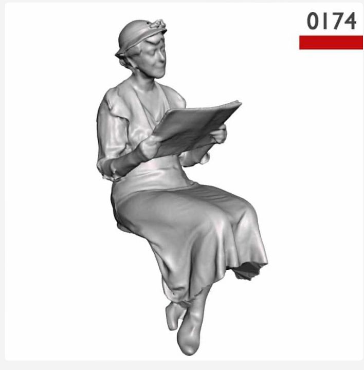
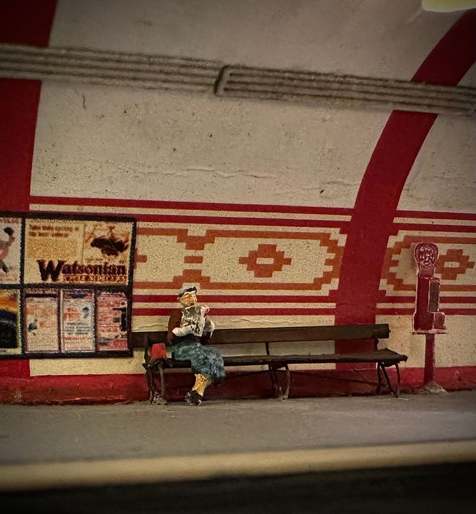
As can be seen in this YR photo the bench along the platform has a lady sitting on it.
The bench was made a few weeks ago from modified Shire Scenes etches. I thought that the lady would best be served by this figure from Modelu
:
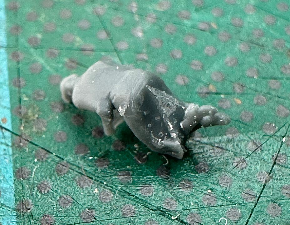
On arrival I was most impressed with the quality of the printing, especially the magazine. Unfortunately, once all the supports were removed I found that the lady had a rather extensive protuberance below her derrière.
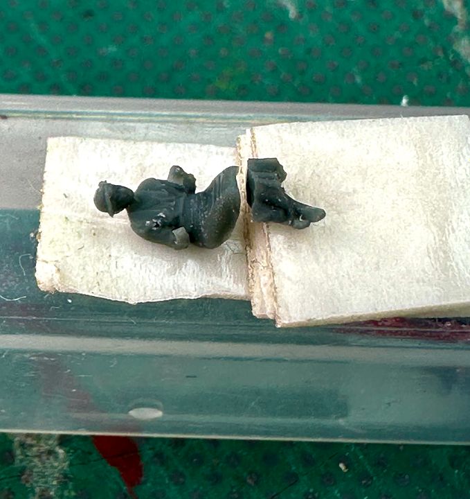
Trimming this away wrote off the magazine and, I’m afraid, the poor girl’s right arm. Even then she would not fit on the bench that I’d made with her coy Princess Diana posture, and would look more like a child perching on the edge of a wall. Serious surgery was therefore contemplated. Those of a squeamish disposition should look away now.
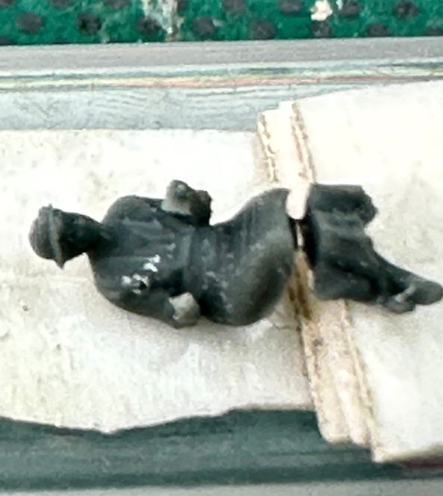
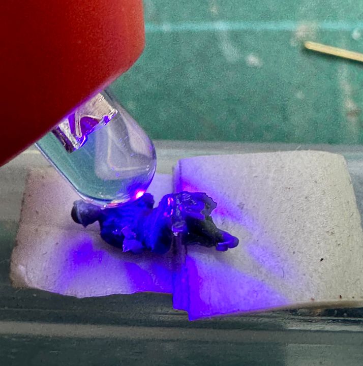
She was electively fractured just below the knees and placed on a thick sticky tape operating table for distraction therapy.
As this was judged to be about the correct length, a small amount of light cured adhesive was introduced into the fracture site and polymerised.
After checking her against the bench the void was made up with more light curling resin added with a pin in small increments.
During the same operation, a new light cured prosthetic right arm was made. After a rapid recovery and following a bit more minor plastic surgery the lady was sprayed dark brown as a base colour and then painted with suitable acrylic wash colours. She is now reading the Daily Sketch, marvelling at the Flying Scotsman’s non-stop run to Edinburgh. Her newspaper was made from cigarette paper and held in place with varnish.
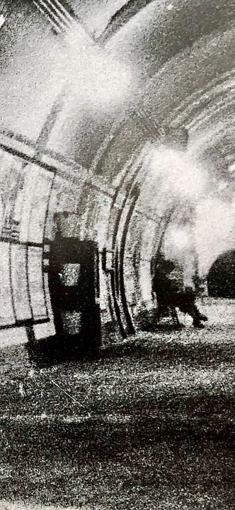
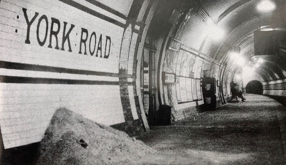
The end result is one step closer to reproducing the B&W York Road photograph and, unlike many figures on model railways, she is sitting properly on the bench with her feet daintily touching the ground.
For all that I think I must be mad to have spent virtually a whole day working on this figure.
Tim
-
23
-
1
-
6
-
11
-
- Popular Post
- Popular Post
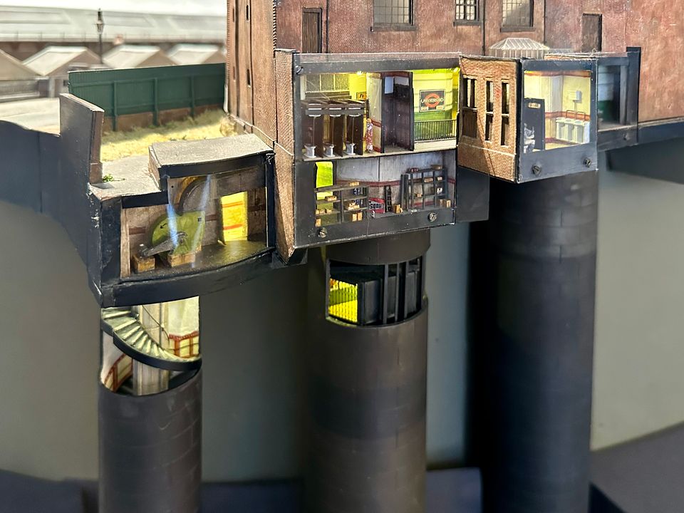
I haven’t posted on WW for a while, but at least I have been doing a bit of 4mm scale modelling for the MRC’s new EM docklands lauout, ‘Orchard Wharf’.
With modern ‘in-house’ laser cutting technology and 3DP components from Modelu, it is quite remarkably easy to make bespoke kit type buildings, which previously would have been a major effort.
Do not fear though, I have stayed true to the faith and continued work on York Road tube station (2mm of course). The model is awaiting a pile of sand.
It will be good to have the youngsters driving the tube train at Ally Pally, where this will be on display in diorama form.
Having cleared the workbench of 4mm office blocks, I will be able to return to the Skittle Alley hopefully in time for Missenden Abbey next weekend.
Tim
-
39
-
12
-
2
-
- Popular Post
- Popular Post
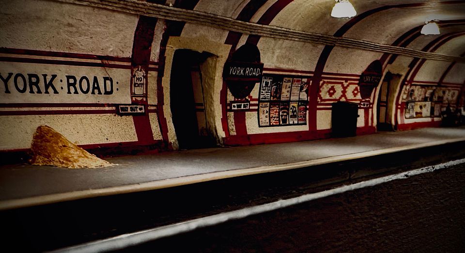
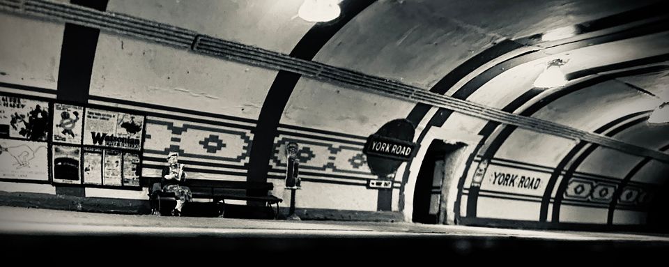
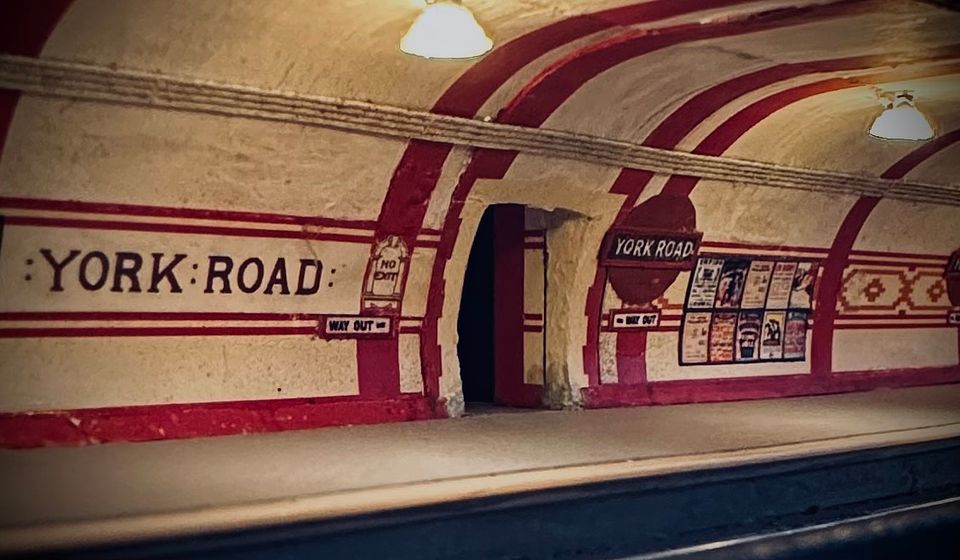
After some careful internet image acquisition & editing, York Road now has a full set of 1920s posters. A pile of fine ballast, bench, fire cabinet and buckets are still needed to replicate the prototype photo.
The images needed quite a bit of cleaning up and brightening before copying & pasting into the PowerPoint file. This software has a useful re-sizing capability and allowed mixing & matching of the posters for variety. The images were loaded onto a dark grey background and then printed at high resolution using an inkjet printer. The original PDF retains much of the resolution of the individual images which are degraded in the photo image. Commercial posters do not generally include the ‘local’ advertisements which are very characteristic of an area.
The edges of the poster boards were touched in with a black pen.
The posters certainly add a splash of colour to the model and help with the atmosphere.
Tim
-
29
-
1
-
9
-
6
-
- Popular Post
- Popular Post
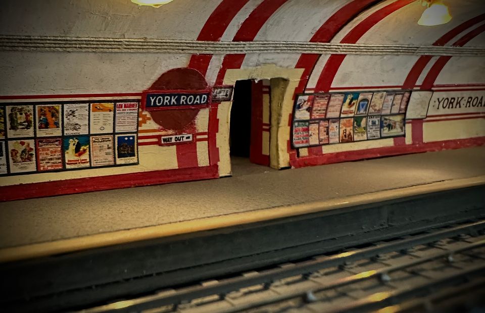
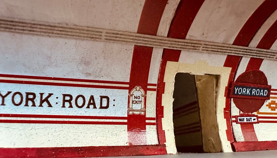
York Road now has its ‘modern’ signage and electrical conduits. It will be on display in diorama form at Ally Pally (16-17th March) on The Model Railway Club stand.
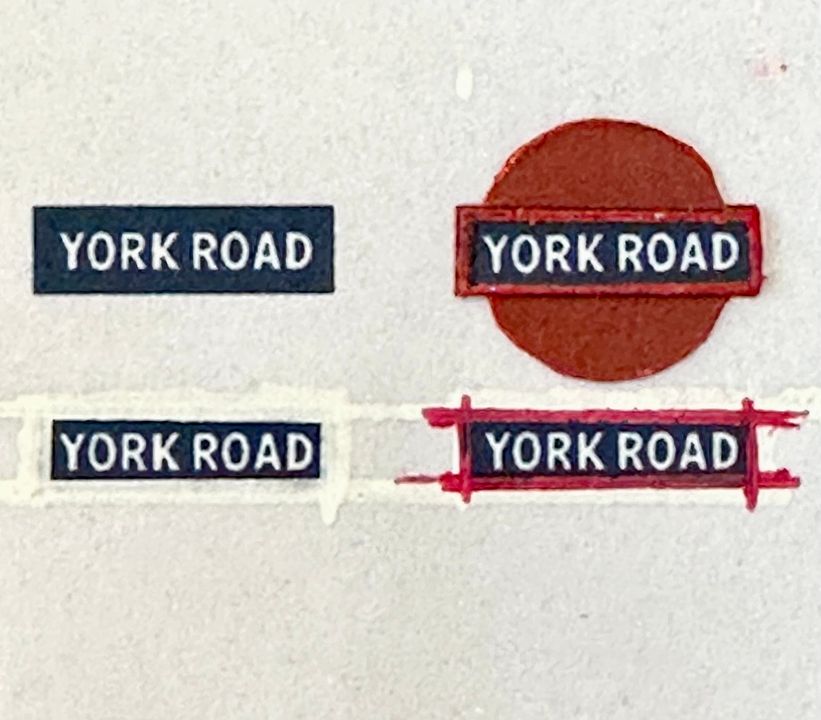
The signs were printed (Ben Weiner made the artwork) and the edge mouldings on the name board were built up with paint.
The signs were thinned down at the back by careful scraping with a #15 scalpel blade to make them less bulky.
The conduits were laser cut as etched strips, by John Jesson, sprayed with white primer then given a wash of stone water-based colour.
The station now needs loads of advertising signs, a couple of benches installing, a Nestle chocolate machine and fire buckets with a hose cabinet.
Tim
-
20
-
1
-
7
-
There are some super buildings and techniques in this current issue but, with few exceptions, they all have no evidence of this being a wet country (especially up north). The background building colours are spot-on and subtly weathered, but there is no evidence of mosses or lichens on any roofs or spreading up from ground level to the lower parts of the walls.
I always use a dark green acrylic based wash on my buildings directed to where they will be damp or holding water. When applied at ground level it makes a structure look as if it is really planted. Perhaps I need to write an article…
Tim
-
10
-
4
-
 2
2
-
-
3 hours ago, Steamport Southport said:
Funnily enough something they got right on the N and O Gauge versions!
Jason
Not on the N gauge one they didn’t! It had a planked running plate and was nearly TT in width.
Tim
-
2
-
-
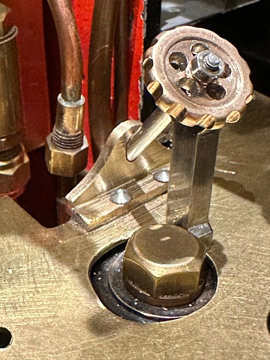
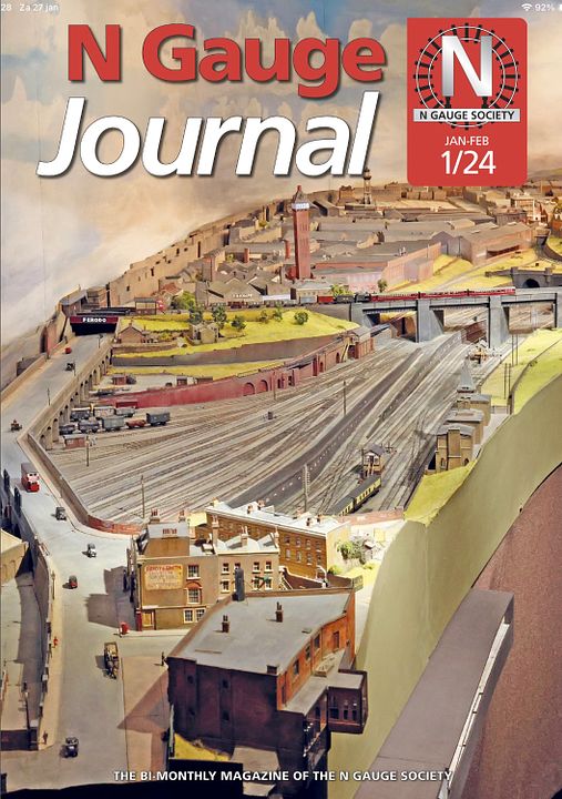
The central trap door on the Sir Sagramore ashpan now has a control / locking device. It’s a bit unorthodox but it will hold the trap door shut when running.
The linkages ended up with a rod pointing backwards at 45deg from the base of the footplate, with it pulled up to close the trap door. I therefore made a steel toggle that holds the rod in the open position:
It rotates 90deg. and pushes in towards the backhead to open the trap door for ash disposal:
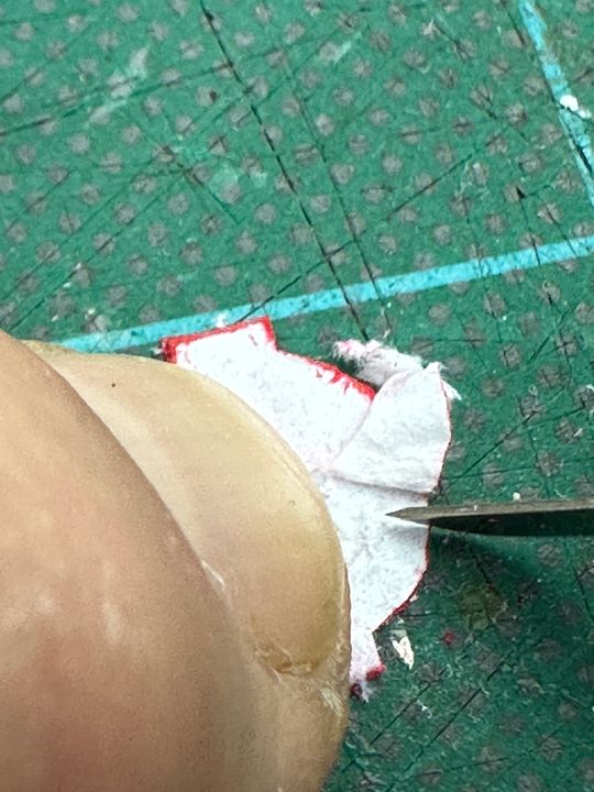
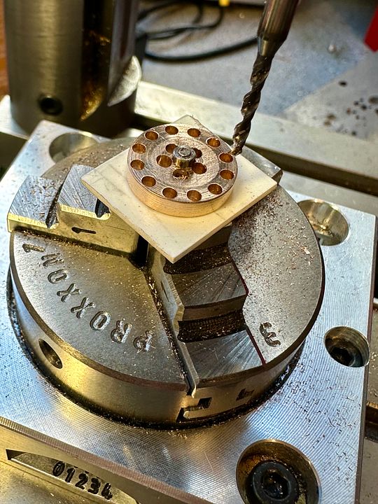
I wasn’t convinced by the appearance of the toggle and it was also a bit slippery to handle. I therefore made a hand wheel to make it easier to hold and also reduced the locking pillar in size. The wheel was turned as a blank and mounted on a mandrel, Loctited in place. This was then drilled on the rotary table.
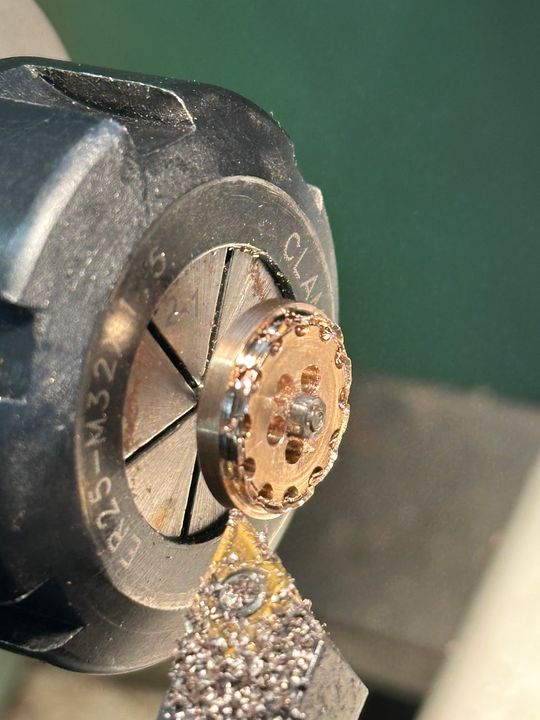
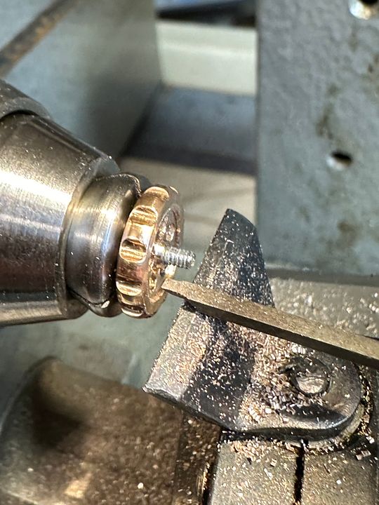
The outer ring was then turned off to give the ‘grippy’ outer part of the hand wheel.
After rounding off the edges the front face was given a rebate using a graver.
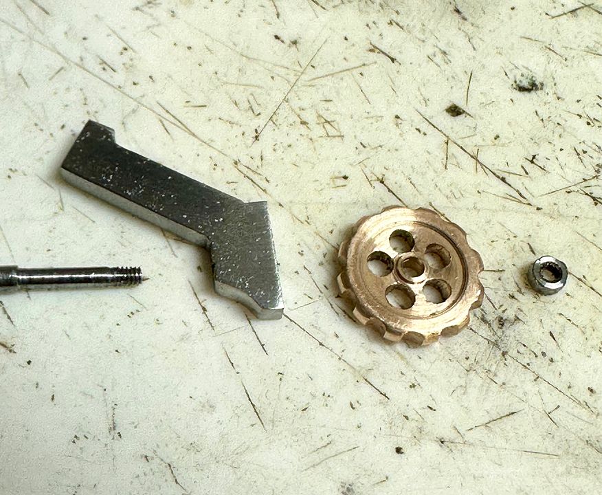
The locking toggle components can be seen here, before assembly. The hand wheel was simply soft soldered onto the steel toggle, and held in place with a 10BA nut, with it pivoting freely on the rod - a piece of coat hanger suitably turned down & threaded.
Finally an exciting video showing it in action!
Back to small scale stuff now.
Tim
-
2
-
3
-
1
-
-
1 hour ago, maq1988 said:
Oddly I would say the opposite, I think you are far more likely to damage the surrounding bodywork scraping off a block of moulded plastic than popping out two contact points for a wire
The problem is that the holes for the handrail stanchions are in the wrong place: there wouldn’t be an overwhelming case to replace these wire handrails …..with wire. The nearest thing to prototype would be a separate etch to represent the stanchions and the handrail with the holes in the correct position. However, as they are painted anyway, I think the moulding is a good bet.
Each to their own tho’…
Tim
-
The art of small scale modelling is what you leave out, not what you put in. The moulded handrails will be far more subtle and if someone wants separate handrails then they could scrape them off and intall their interpretation of the prototype.
Tim
-
2
-
-
39 minutes ago, bécasse said:33 minutes ago, woodenhead said:
Finescale pointwork is available for N.
But you'd imagine the N scale society know the difference, maybe inside it explains why it's put a 2mm FS model on it's front cover.
It really doesn’t matter what the difference is in the trackwork between 2mm FS and N gauge, it’s the overall ambience of a layout that matters. However, when Keith Armes made the mainline crossovers from a scaled up prototype track plan, he remarked that they were the longest turnouts he had ever made. They could not work with N gauge standards.
Tim
-
8
-
1
-
-
The excellent picture was clearly taken at Warley with the stealth tube present; since modified to be more visible. It’s a Zeppelin view, but none the worse for that. Can someone say what the caption was?
Tim
-
7
-
-
News to me! Is it decent?
Tim
-
1
-
-
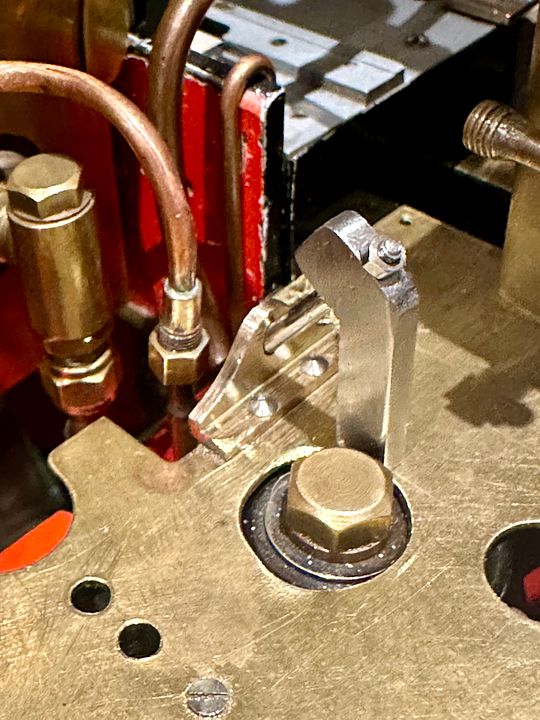
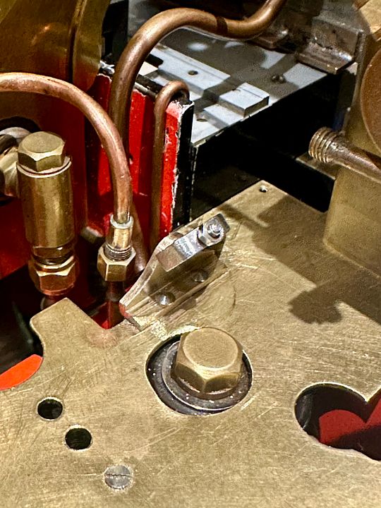
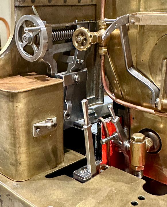
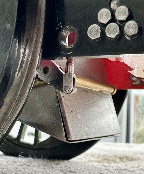
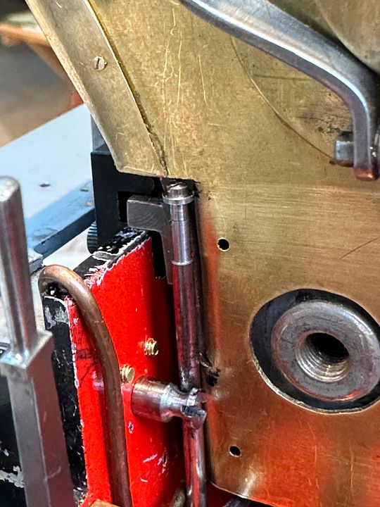
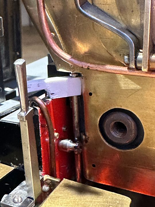
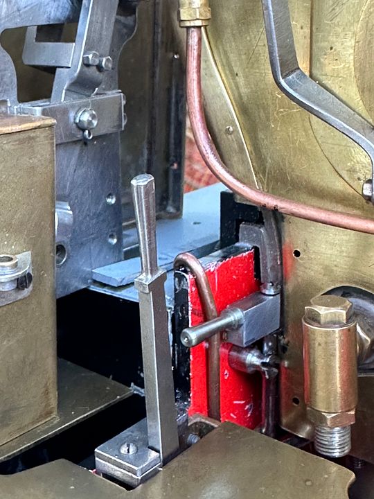
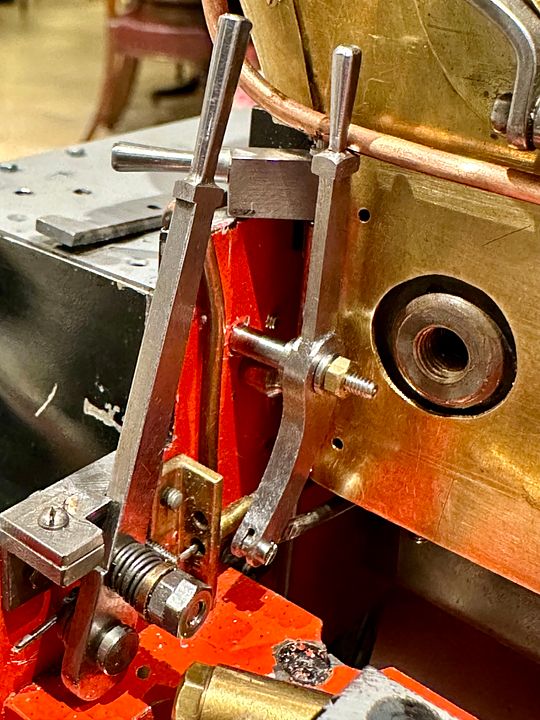
After an inordinate amount of thinking and puzzling I have now made the front and rear damper linkages for Sir Sagramore.
The rear linkage is simply a rod that links to the damper clevis and snuggles in close to the back head.
The rod is located by a grooved bobbin that centralises it with low friction. The top is rebated and has a separate top hat 12BA bolt assembly.
This rod has a rotating handle that locks it open by resting on the frames (a detent will be filed in when the boiler is next removed). To rest the concept, a lump of styrene was carved to shape.
This was then converted to metal and can be seen here with the handle in closed position. It will be prevented from moving medially by the support component of the front damper.
The pillar that supports the front damper lever has a rebate to locate the rear damper body when in the closed position.
In this image, the dampers and drain cocks are in the open position; the brass nut will be replaced with steel.
I have tried to maintain the style of Ian Jaycocks’ work with these new components.
Tim
-
6
-
-
Thank you for the help, Edwardian.
Herewith a photo of Stephen’s loco, completely scratch built except the wheels, gears and motor.
It weighs in at 70g.
As a retired dentist, he knows how to get a good polish on the dome, although I suspect it is not in non-tarnishing metal.
Tim
-
5
-
6
-
-
May your links always vibrate nicely…
Tim
-
 1
1
-


Hue must be joking...
in Modelling musings & miscellany
Posted
Nah… Go for broke, get those clouds in!
Tim