


LCUT_creative
-
Posts
184 -
Joined
-
Last visited
Content Type
Profiles
Forums
Blogs
Gallery
Events
Exhibition Layout Details
Store
Posts posted by LCUT_creative
-
-
One thing to maybe consider is perhaps producing various brick course styles; English, Scottish and Flemish for example are all very distinct and from observation of Caledonian signal boxes just to quote a personal example, the brickwork is almost entirely Scottish bond.
Just a suggestion.
Dave.
Hi Dave,
The main reason we are not making the brickwork in different bonds is the interlocking would not work very well as well as the corners. We are aware that plain bond is not the ideal type of bond to use. We have experimented with different ones some time ago and it would not be viable. However if we find a way of manufacturing them to an acceptable standard they will be introduced.
-
 1
1
-
-
Introducing O gauge small goods shed
Another popular bundle from our OO gauge offer is now available in O gauge!
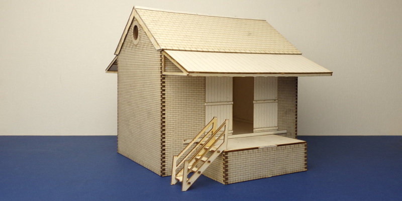
http://lcut.co.uk/index.php?product=B%2070-08&title=B%2070-08
-
3
-
-
Just a brief note to thank Jakub for the quick turn around. Exactly one week since my enquiry above I received a small package containing the bespoke items along with some of the standard products.
Great service!
Thanks,
Alan.
Hi Alan,
Thank you, glad to hear you are happy! Let us know if there is anything else we can do for you.
-
1
-
-
Is it possible for you to produce an "angled" length of valence in 7mm to match the straight piece? I am looking at scratchbuilding a station building based on Wallingford.
Hi,
It would be possible. Please send us the details (masurments, scketches etc...) to contact@lcut.co.uk and we will take it further from there.
-
1
-
-
Introducing O gauge medium signal box
Signal boxes in O gauge has arrived starting with the ever popular medium signal box! Available in both left and right stair versions which are available separately.
As always when existing products are rescaled to O gauge a number of improvements are made. Starting with the chimney which now includes flashing and 3D printed chimney pot. Furthermore a point rod walkway has been added following up on feedback we have received. Keeping with the improvements in the instructions we provide each signal box with detailed set of instructions as well as suggestions and technical tips and tricks.
http://lcut.co.uk/index.php?product=B%2070-07L&title=B%2070-07L
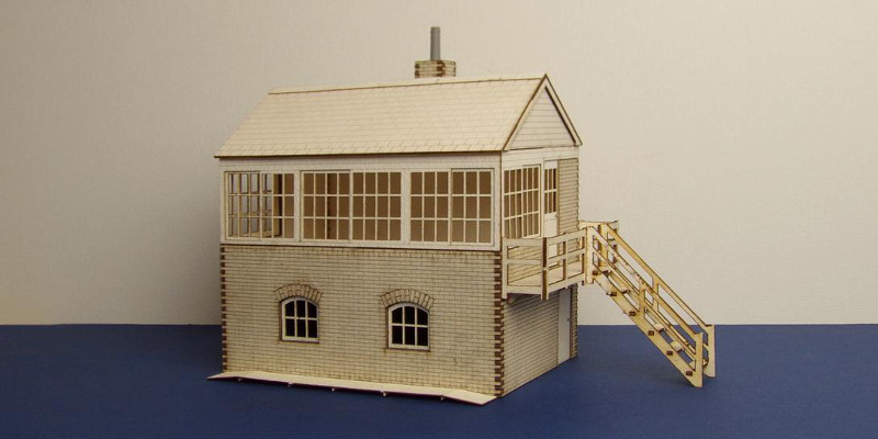
http://lcut.co.uk/index.php?product=B%2070-07R&title=B%2070-07R
-
2
-
-
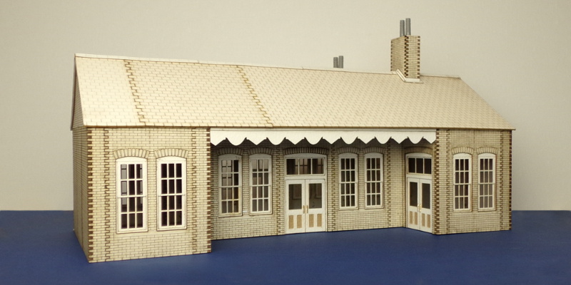
Introducing O gauge station canopy
Another popular bundle from OO gauge arrives in O gauge!
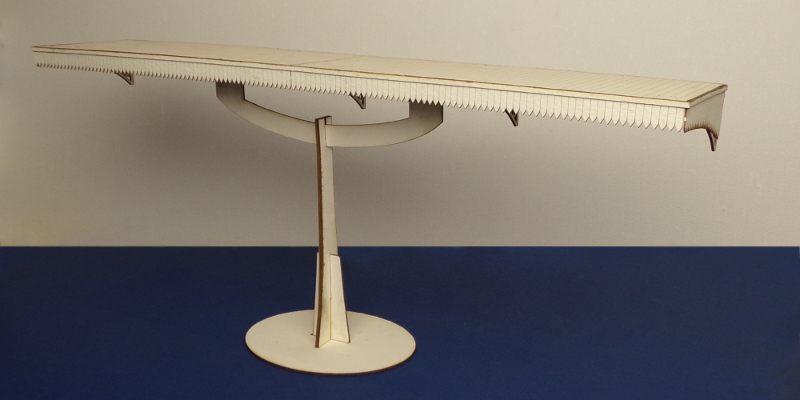
http://lcut.co.uk/index.php?product=B%2070-06&title=B%2070-06
-
2
-
-
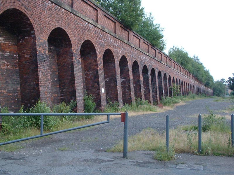
Here's a picture of a recently built viaduct. It's been painted with watercolours and still needs a bit of weathering added.
Thank you very much for posting and answering that question. The paint job looks really lovely!
-
One of the most popular bundles from our OO gauge range is here in O gauge!
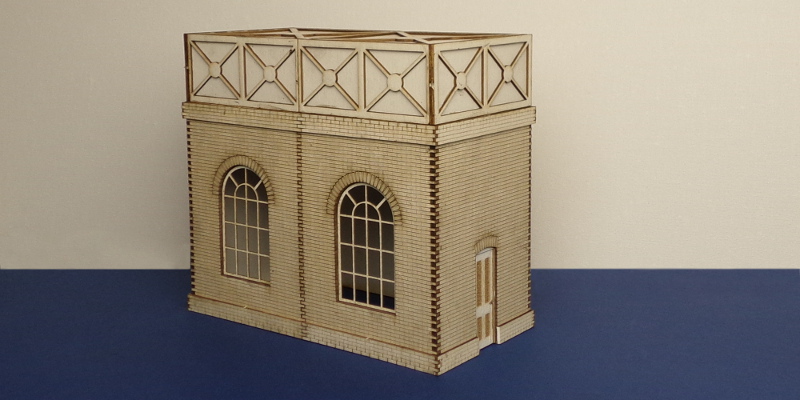
http://lcut.co.uk/index.php?product=B%2070-05&title=B%2070-05
-
Hi,
Thank you for the support and feedback!
We would like to cater to all of the brick bonds but sadly we can't. It would not work with the interlocking parts. Especially with OO gauge it would make the corners/joints very unstable. If we ever in future find a compromise between more accurate brick bonds and being able to keep the interlocking parts we will introduce version of those.
Must admit I am very impressed. As I could not get to any of the shows, I ordered a few samples last week to try them out and received them very quickly. My only quibble is there only being one type of brickwork on offer. I know that if new bonds were offered then everyone else would ask for other different ones. I am hoping to be able to modify the bond , into garden wall bond, by covering up or rubbing down every 4th row, and re-cutting into headers.
I am planning a Manchester/Lancashire warehouse building in 1/76 scale, and gwb was the standard for NORI brick buildings this size. I have also seen a local building with every 5th row as headers, but every 4th row seems to be more common.
Plan B is to cut up some Slater brick sheets(English and plain), but I like the feel of the lazer cut bricks.
-
Starting with B 70-04 we are introducing stations in O gauge. Keeping with the spirit of improving on the models when rescaling to O gauge we have introduced additional, small yet important, details. Thanks to the 3D printing technology we are now able to make good looking chimney pots. Further improving the chimneys, chimney flashings are now available and included in station bundles. In addition sash windows have been separated into two parts which allows to assemble them in open configuration. Finally we have improved the instructions included in the manual after feedback we have received.
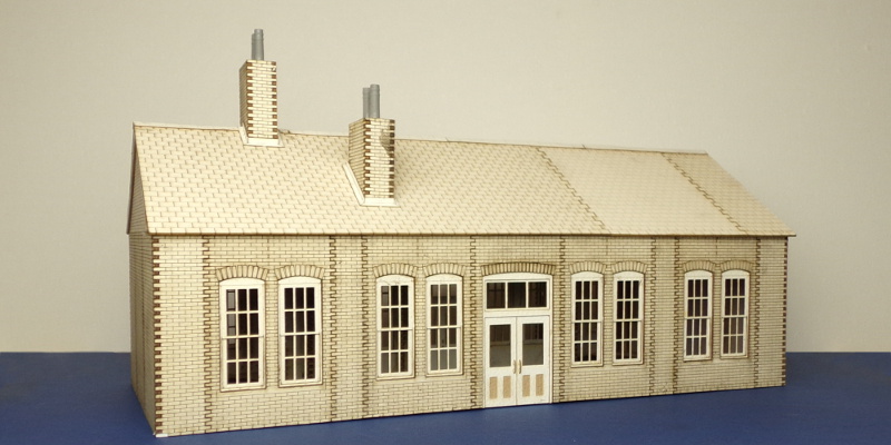
http://lcut.co.uk/index.php?product=B%2070-04&title=B%2070-04
-
1
-
-
I'm working on that one and will e-mail you a list of 'parts' (or more correctly their specification) when I get that far. It will have to be assembled around the baseboard top, so the parapet walls will be above the baseboard with the rest below. For the above baseboard structure, I envisage using the same parapet sections from the retaining walls and tunnel portal, albeit the length will probably have to be adjusted to match the below baseboard dimensions. That is the relatively easy part. It is the section below the baseboard top that I am less clear about. The image here isn't particularly good, but it gives an idea of what I would like to create. That is, two arches, where the watercourse flows through the one on the left and the adjacent arch is used for agricultural movements (in my case a Land Rover track rather than steps). I notice in this image, the arch is in brickwork, although I was actually thinking about a stone arch more like this one which was my reason for starting with the double round door panel. However, looking at photographs like those that I have linked to, there always seems to be an angle between the wall and the arch. That is, there is not a continuous curve as there is with the doorway, which I hadn't actually realized until now.
If it has merit as a potential kit, then separate arches and retaining walls would make sense as it could then be expandable to include more, or fewer, arches if required, but as a one off commission, one piece would be good. It would fit within the maximum sizes that you indicated above.
I will assume that I will need some wing walls, albeit these will probably just be cut down versions of the ones in your over-bridge kit. I'll probably need to assemble the arches and parapet and then look at the subject of of wing walls once the core structure is embedded in some scenery. I'm just posting here in case anyone else can give me feedback.
Thank you for the photos and additional information, it is all doable. We can do it after GCR Model Event. We can make in leaning version as well as straight version, whichever one you think will be best in the end.
-
Thanks for your response, which was pretty much what I was hoping for. Slight deformation is not a major issue as the brickwork would not be that visible. The image below (assuming this works) is an indication of what I would like to do.
Basically I would like to create an agricultural underpass and culvert under a double track mainline. When the railway was built in the 19th Century, it would probably only have been large enough for the passage of animals from one side of the railway to the other. However, I would like that passageway to be wide enough and high enough to accommodate a land rover (sorry I only have a Network Rail version) or a small tractor (of which I don't have any at the moment).
The image above uses LCC 02-09, which is a double round door panel. This is slightly too small in terms of width and therefore a slightly larger version of this panel would be useful. The obvious starting point would be to create a cross between LCC 02-09 and the larger industrial building wall panel LCC 04-18, which is approximately 9 mm (three bricks) wider than LCC 02-09 and approximately 12 mm higher. This therefore means that these panels could be used for the ends of the structure (ie the sides of the abutments).
The bridge parapet could then be fabricated using a variation of LCC 00-102, but with a cut out in both brick pieces, such that two all brick panels in 0.7 mm fiberboard could be combined back to back between these to create a parapet wall with an overall thickness of approximately 4.5 mm. The ends could then be tied together using a narrow panel (half the width of LCC 00-02). I think that this would be a worthwhile variant of the retaining wall parapets as well, but that is a different conversation for now.
LCC 02-09 has an opening width of 23 mm, so if this was increased by 9 mm, then the internal arch would have a radius of 16 mm. If you can make a half inch pipe, then clearly this should be possible. The principal issue is the need to join the curved inside to the archway. I'm not sure if it would be easiest to do this as per the retaining wall sections with a thicker upright either side of the arch, or whether the arch should have a cut side with the same profile as LCC 02-42 so that the 0.5 mm arched piece would connect in the same way as the two halves of LCC 02-42 are intended to mate together.
I'm interested in any comments before specifying some more bespoke pieces.
It will all be possible to do. All I would need is bit more detailed specifications such as:
- Underpass and culvert style
- Culvert dimentions
- Embankments
Finally I would need to know how do you think it all should go together. Should all of them be a single unit or separated?
-
Can you advise on what radius you can bend the 0.5 mm board? That is, I am looking at this for the curved roof of an agricultural underpass.
Can you advise on the size limitations of the laser cutters? I am looking at specifying a few more bespoke items.
I really should be gluing some of the 100 + components that I have ordered to date together, but I am still exploring a few other uses of this product (whilst I have enough pieces to play with).
The 0.5mm material is flexible enough to make into half inch pipes (in theory). The only problem you would run into is slight deformation of the inner side (as it is being compressed).
Size wise the limitation is the max board size we can fit which is 390mm by 290mm. Smaller parts are limited by the dot size which is about 0.2mm (dot size - laser beam size, hole it cuts in the material) Generally the minimum width of parts is 0.7mm with the materials we use.
-
Nice! Any possibility of 7mm ones in the future?
Jim F
Hi Jim,
Thank you! Yes there will be 7mm interior. We have few prototypes at the moment but I don't know how long it will take exactly.
-
1
-
-
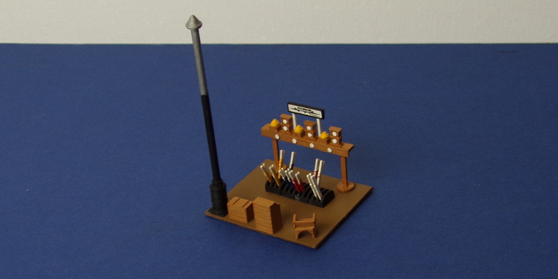
Introducing OO gauge signal box interior
Mixed 3D printed and laser cut signal box interiors are here! The range includes small signal box interior, medium signal box interior and an extension kit.
Small signal box interior:
Medium signal box interior:
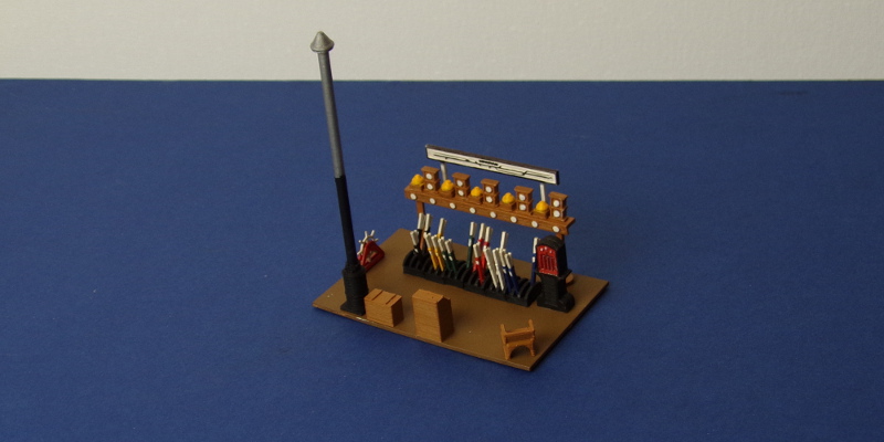
We also have an extension kit for the medium signal box interior kit:
-
8
-
-
Hello....having read about LCUT kits, I ordered a brick arch kit with warehouse fittings to have a look for myself....if I'm honest, I was a bit sceptical about the accuracy of brickwork relief and crispness of detail on window frames, etc. However, following really quick delivery, I'm really impressed....I was prepared to replace the windows with ones made on a silhouette cutter, but although the bars work out at a scale 1.71" ( a little thick), theyre so nicely cut I can live with it. I've started to experiment with painting, as the absorbency of the wood is going to be an issue: I think a sealing primer might be the answer, and I'll post my results for your interest. However....a really tiny niggle, which seems unfair on such a great product, but: The doors on the model have the bracing on the outside, where it would almost certainly be internal...any chance of producing the doors without the bracing (just simple vertical planking) or even with an integral door for people to enter? I'm guessing it would be a really easy amendment to the CAD file, and whilst it would be easy to scratchbuild the doors, I think it would improve the kit a bit.
Thanks for a great product at a reasonable price.
Thank you very much! I am glad that you like it.
Few coats of light primer will seal the surface. I generally use this to my advantage, you can get interesting shades of colours and textures!
We certainly could produce door without bracing. I will look into it for you if you are interested.
-
Looking at the platform pieces that I have purchased, I can’t believe that I am the only one who has platforms that cross a baseboard join at right angles. Whilst the standard station platform internal support (LCC 00-46) appears perfectly adequate for constructing internal bracing to support the platform deck and maintain spacing between the walls, at the baseboard join, it would be useful if there was an alternative support, which was the same width as the standard support (approximately 63 mm wide) but had interlocking brickwork at either end to connect with the main platform walls, thus helping to keep everything square. This would help to give any platform structure rigidity at the baseboard edge where it is perhaps most vulnerable. They would not need to be scribed with brickwork for this purpose, but a scribed version may be more versatile: I’d like about 18 in total if it could be used as an alternative length of wall.
.
I would have thought that these could be included in a cross baseboard platform extension bundle, since 614 mm is rather short for a platform (as per LCC B 00-07) and anyone purchasing this bundle is likely to want to extend it without purchasing too many end slopes.
I am also unsure why the platform walls come in both 99 mm (LCC 00-41) and 198 mm lengths (LCC 00-47), yet the platform pavement panels only come in a 99 mm length (LCC 00-43). Have you given any consideration to producing a longer, double length platform panel, which would reduce the number of joins required on the platform surface? With 1.6 metre long platforms (which I don’t think is unusual), I would need to have approximately 15 joins and anything to reduce this number would, in my opinion, be worthwhile.
Regarding the Early 20th Century country railway station (B 00-00) this contains part LCC 00-12. The instruction leaflet included does not indicate where these are intended to be used, although I assume that they are intended to be platform level decoration. I think that I will be missing these off my station building (and using them as platform decoration strip), but perhaps the instruction leaflet should be updated to clarify. There also appears to be what looks like two lollipop sticks in the kit, which I presume are intended to be cut to form the chimney pots (LCC 00-08). Again, clarification in in the instructions may be helpful.
That said I’m happy enough with the bits that I’ve purchased so far. My only criticism is that I find it difficult to remove the LCC labels from above windows and doors without damaging the top layer of bricks. I’m not sure whether a scribe or mortar line separating the panel from the label would help.
Thank you for yet more useful feedback!
I will look into the options you suggested for the platforms. I cannot promise more than double or triple the length pavement panels due to the size limitations of the laser cutters we have. It certainly is a good idea and we will look into it.
B 00-00 manual is on the list for an update. Quite a lot of the manuals are going to be updated following on the recent feedback. We have started adding a mortar line to the labels on panels with O gauge now. We are also considering slowly phasing in OO gauge parts with said like as well. I cannot promise when that will happen but it is on the to do list as well!
Thank you again for the continued feedback. We really appreciate it!
-
1
-
-
Thanks for posting the prototype inspiration for the retaining wall unit. I'm still trying to think how I could use this given that I want a retaining structure that is curved in plan and declines in height moving from left to right. I'd also like replicate the moderate lean back found in prototypical retaining walls. I can see this being a challenge.
Looking at the prototype photograph you have posted, the arches are in a vertical plane and it is only the buttresses the slope at a moderate angle. As such, to have a tapered top, I think I will need to make the arches lower down and simply vary the height of the brickwork above the arch. That is, potentially use the communication tunnel as the 'standard' arch and cut down the back piece as appropriate. This probably means some customised supports, with a modified form, ie a greater vertical area and a lesser sloping height.
However, I seem to be getting into a large list of bespoke items (new over-bridge parapet and deck, a culvert head and wing-walls, customised platform wall length, station steps and now modified retaining wall parts). As such, it probably makes sense that I just order £30 worth of 'standard' bits online, see how well it goes together and then get back to you with regards bespoke items.
I do have one last question on the retaining walls though. Can I confirm that the front pieces LCC 00-97 and LCC 00-100 are supplied flat and it is only when glued to the support pieces that they become curved?
Yes, LCC 00-97 and LCC 00-100 are supplied flat. The normal supports will work with the communication tunnel. You will just have to glue LCC 00-99 lower. In fact that is how the first prototypes of the communication tunnel were made before we made it open. The left most element from LCC 00-97 will also work instead of LCC 00-107. I still have the project and can make parts for you to make the arch with communication tunnel's front face.
-
I agree with Kenton insofar as I think that the recess 'looks' too deep, although it may be prototypical in some parts. Looking at the image for LCC 00-97, it appears that the recess is five brick lengths deep, which I assume must mean 15 mm or approximately a scale three feet and nine inches. However, I see no reason why these parts could not be reduced in depth if required by cutting say 3 mm off one side of each part. I'm not sure whether the side supports LCC 00-98 would also have to be amended as there is not a manual for this kit on the website, but looking at the images of the assembled retaining wall, it looks as though LCC 00-97 is the only part that separates the front face (LCC 00-94) from the recessed wall (LCC 00-96). Perhaps I just need to buy one of these to test out my theory.
The retaining wall was inspired by one of our customers, this is the retaining wall we were inspired by:
You are right in saying there is a lot of retaining walls with shallower recesses. This one however was made by request. I will look into making them shallower for you, there shouldn't be any changes to the back supports as it will be the same angle.
Apologies for the manual not being online. I will upload it tomorrow.
-
1
-
-
Thanks for the reply,
With regards the steps, I was looking for something that would be around 32 mm (a scale eight feet) wide. I assume that a bespoke construction would simply be a pack of longer steps to replace those in LCC 04-42. If this is correct, then that would be great (although I'm not sure how to order bespoke products on-line). The lack of a fence is not an issue as I was originally intending building a wall (the equivalent to a platform wall above platform level and twice that height from street level, so I will probably stick with that plan.
With regards the platform wall, I think that it is important to maintain the interlocking, and I think the 39 mm long wall would be better, since there will be an overhang on the platform surface. Better still would be a 90 mm long panel to save joining 51 mm and 39 mm panels. Again, unless you add this to your Catalogue, I am not sure how to order a bespoke item on-line.
No problem!
Just drop us an email at contact@lcut.co.uk and we will take it from there.
-
Thanks for the reply, but as usual, I seem to have yet more questions about your 4 mm products.
Product LCC 04-42 "stairs for goods shed office basement": what width are the stairs and would it be possible to use two or more of these products side by side to create a wider stairway? As you can probably guess, I am looking at an alternative use: a stairway from street level to platform level (street level being about the same as track level). Whilst entry to a goods shed may be one person at a time, station steps would have to allow for the movement of a crowd, so need to be wider. Also, is there a similar fence unit to extend the railings on the step? Alternatively, what height is the fence and would it tie in with LCC 00-91 (which seems to be 20 mm in height)?
Also, there seems to be three lengths of brick platform wall: LCC 00-48 (51 mm); LCC 00-41 (99 mm); and LCC 00-47 (198 mm). Do you intend making any other lengths? I am looking at building a terminus with an end wall that connects the two platforms. As such, I would be looking for a section that is approximately 86 mm plus twice the thickness of the decorative facing, so about 88 mm. Unfortunately, I can't see how I could do this without either an 88 mm platform wall or alternatively a circa 37 mm platform wall that could be combined with the 51 mm section (LCC 00-48). A longer section would also be useful, but I appreciate that 198 mm may be the longest length that you can produce.
I can see me making more than one order at this rate, since trying to produce a single shopping list is not easy!
Hi,
The best way to tackle the stairs would be to make a simple bespoke construction for you. It would technically be possible to double them up but it would not look very nice. If you tell me the width you need I can prepare them for you. The railing in LCC 04-40 and LCC 04-41 is about 15mm in height. At the moment we do not have fence that could match up with that.
It won't be a problem to prepare a section of that length for platform. But if you want to keep the interlocking it would either have to be 36mm or 39mm in length. Again other lengths won't be a problem to prepare for you but if you intend on keeping the interlocking they may be few mm off.
Please let me know what do you think about it.
-
Can I ask what governed the choice to make the parapet 91 mm in length?
My understanding is that in 1:76 scale bridge piers (and presumably abutment walls) should be 30 mm from the centreline of the track. That is, they should be further from the track than say a bridge parapet or platform edge. (see here). Therefore, a bridge spanning a straight section of single track should have a parapet that is 60 mm in length. If the track is on a curve, then a longer parapet would be required, but I would have thought that something like 70 mm would generally have been considered acceptable.
However, for double track the minimum parapet length spanning straight track should be 30 mm + 45 mm (assuming scale track centres) + 30 mm = 105 mm and if working to a 50 mm track centre (as per PECO streamline and the RMWeb Challenge), the minimum parapet length would have to be 110 mm. To accommodate a four foot radius curve under the bridge would probably necessitate increasing the parapet length to something closer to 120 mm, although it is not critical. I realise that I could splice two sets of parapets together and do the same with two sets of bridge decks, but would you consider creating longer parapet sections? Better still, would you consider something that could be extended in the same way as your building roofs with a left and right section? For my attic layout, I could be tempted by circa 170 mm parapets that would span three tracks. I'll have another look at the top of your retailing wall tunnel portal for that purpose though.
Thank you for the extensive post! The measurements for overbridge are taken from existing plans in 4mm scale with straight track in mind. I can however prepare longer parapet and deck for you if you wish. We could make the extensible parapet. It would most likely be section per track (then you could have 3 sections for 3 tracks, or 1 normal parapet and one section for 3 tracks). I will get back to you when I've done some prototyping!
-
1
-
-
Massive +1 for this company. Ordered a number of items late yesterday afternoon and delivered this morning at 10. Faultless and highly recommended. Usual disclaimer - no connection just a (very) satisfied customer.
Thank you! Great to hear everything arrived safe and sound and that you liked it!
-
1
-
-
Two quick questions:
1 - Is the back wall of the retaining wall adjustable? I don't know where the prototype is from but it just looks far too deep for any that I have seen.
2 - I thought it wasn't possible to bend this wood, Yet that retaining wall communication tunnel appears to be quite a sharp radius form?
The back is not adjustable per se. You can omit the recess by glueing the back directly to the front. It is based on an actual retaining wall measurement wise.
You can bend the 0.5mm, 0,6mm and 0,7mm fibre boards. We use them in situations like this. The typically used 1.4mm fibre boards can be bend a little bit but that much.


LCUT creative
in Smaller Suppliers
Posted
Hi David,
Thank you for the pictures, it turned out lovely!