

SouthernRegionSteam
-
Posts
1,325 -
Joined
-
Last visited
-
Days Won
2
Content Type
Profiles
Forums
Blogs
Gallery
Events
Exhibition Layout Details
Store
Blog Comments posted by SouthernRegionSteam
-
-
7 hours ago, Dave John said:
I added a gallery with some detail pics which may be useful
All I can say is that is absolutely superb, and will be extremely helpful when I get around to building the swing bridge - a wealth of detail there!
I ordered a sheet of rivets in preparation; but I think, on further inspection, I might need more than one...
Thank you very much, I really appreciate the photos!
Jamie-
 1
1
-
-
27 minutes ago, Dave John said:
This is a photo of the canal swing bridge at Port Dundas in Glasgow, which is still there.
It is a slightly different design to yours, but I do have a lot of photos of the mechanism which could be useful when you get round to detailing yours.
Happy to send them to anyone.
That's fantastic, Dave! And perhaps unsurprisingly, it's another prototype I looked at:
Any additional photos would be very gratefully received; thank you very much for that offer! There don't seem to be too many photos of swing bridges; but I guess that's because they were probably in areas where the general public wouldn't be allowed. Port Dundas is a particularly good example as it's so small, and obviously still exists!
Thanks again!
Jamie-
1
-
-
4 hours ago, Mikkel said:
Thanks for an interesting read, Jamie. The photos and drawings of the baseboard framing was useful for someone like me, who tends to use cave-man approaches to such things.
I enjoyed that test shot of the Q1 on the swing bridge, made it all come to life. Looking forward to more, I think BRM should just pay you full time to build the layout 😄
I'm really glad it was useful, thank you, Mikkel!
Whilst I'm not an expert on baseboard design and carpentry, my dad used to be a carpenter before he retired; so I have access to both knowledge and tools which have proven incredibly useful for building model railways - as you might imagine. I don't think there's a wrong and right way to approach baseboard design, but knowing the characteristics of materials is incredibly important; especially their weight (I'll never ever use MDF for anything that's meant to be portable again...)!The main thing is to do whatever works for you. By all means, learn new skills and techniques, and try out old materials... but if your old approach works for you and you can't 'get on' with a new approach; then it's absolutely fine to stick by what you know.
Anyway, yes, the shot of the Q1 was also the point for me at which I could see it would all come together nicely.
As for the last part, I couldn't possibly comment!! 😅😁-
1
-
-
10 hours ago, kitpw said:
https://www.pinterest.co.uk/pin/658721882970201795/. Pinterest "cards" which include the Rolles Quay access swing bridge (Pottington). I believe it was originally an iron drawbridge before installation of the swing bridge but have no reference for that. There is better reference for the swing bridge at Hayle which looks to be broadly similar to your sketch for Coastguard Creek - but now replaced.
https://upload.wikimedia.org/wikipedia/commons/d/d7/Hayle_wharves_swing_bridge.jpg
Thanks for this! I had actually found the photo of Rolles Quay - and as I don't know the area at all well, I assumed this was the Pottington one. However, looking at the Pottington photos I linked before proves it was actually a completely different bridge. Obvious now, but not at the time! Had I not seen Pottington, I would've probably gone down a similar route to the Rolles one.
Hayle is the main one I originally thought of when wanting to add a swing bridge. It's a good one to show how most swing bridges with their pivot on one end have much of their span over land to avoid using too many counterweights.
I don't want to say who (that's up to them to say), but someone has amazingly provided me with 3 photos of the Pottington bridge (plus one of the signal box) which has been incredibly useful as it shows it was indeed a small swing bridge in terms of having very low girder sides; which is exactly what I want. It's also got a wealth of other things that I now want to include on the plan. Additionally, I'm now tempted to do away with the brick arch so that I can have a more spindly iron structure with better views beyond the bridge.
Lots to consider!-
1
-
 1
1
-
-

I genuinely had an amazing time travelling up to Cardiff; spending I think 6 pleasant hours marvelling at the layout and snapping away merrily. Those reading this blog who haven't yet seen Sherton Abbas, you simply must see it for yourself if you get the opportunity; it's such a stunning layout!
I'm very grateful for Dave's hospitality and humour throughout the shoot, which resulted in (what I feel) is a very interesting, entertaining, and natural-feeling video. The layout doesn't half scrub up well, too 😆
I couldn't ask for more from a photoshoot. It was a real treat to get to do it!
Thank you, Dave!
Props go to @AY Mod for the additional photo editing, and the designer(s) at BRM for bringing everything together cohesively!
-
4
-
 1
1
-
-
A problem I've found with the turntable is the difficulty of adding/shuffling wagons; particularly to the centre track. The track spacing (due to the curvature required) isn't very generous, to put it mildly! I'll have a little think on it before I rush into any decisions though. I suppose a traverser might be another option, provided there is the necessary space there. Time to do some mock-ups!
-
1
-
-
5 minutes ago, SD85 said:
I think I got into the vibe of it and just found it relaxing to shunt. The only aggravation really was as you said the couplings and the sector table alignment, but those are fixable.
Yes, the turntable (which, as you rightly point out, is only ever used as a sector plate!) definitely needs fettling. Perhaps I should rebuild it into a sector plate and get rid out the trio of unused spurs in the fiddle yard 🤔. It might well be worth doing. I believe the ply top is only screwed on, so a rebuild of the fiddle yard shouldn't be too onerous! Edit: Or, perhaps just use some cassettes... -
11 minutes ago, SD85 said:
I came down from Croydon, not Luton, just to clarify. But yes, I did go to the Basingstoke show to see the layout and very glad I did, it oozes atmosphere and is very much a place where (IIRC) you said nothing really happens in a hurry - nicely languid. Good to see you last weekend as well!
Croydon - that was it! Curse my terrible memory... 😅
I had a very enjoyable time, and it was lovely to have such nice company. I'm amazed that the layout preoccupied you for much of the day, but I'm really glad you were enjoying it! I definitely need to get those uncoupling magnets and couplings working properly though; the new beach huts certainly provided a new obstacle when shunting the front siding, as you soon found out!-
1
-
-
21 minutes ago, Nick C said:
Given that the whole spur would probably be run under "local instructions", with no passenger movements, and under wartime conditions, I suspect you can probably do whatever you like, within reason, and provided all such movements stay 'within the gate' - which is of course offstage somewhere... Perhaps with a figure in suitable officer's uniform keeping a beady eye on things...
Ah, OK - I think I understand now - I was looking at the wrong siding(s)! So, essentially, after having shunted the train ready for the outbound freight, you're coupling that up to the brake van from the SR train that's just arrived; so that you can 'steal' the brake van and put that now-completed outbound train back by the loco shed. Then the Ruston is parked somewhere out of the way, allowing the SR train to run around the train it had just hauled in, reversing back to the train that the Ruston had just assembled, and then taking that back to the fiddle yard ready for the Ruston to shunt the train already in the loop? Is that about right?
Gosh it gets confusing; I should've given the sidings each a number for people to reference if they needed to, as it becomes hard to explain what you mean without it becoming a long paragraph of descriptors!
24 minutes ago, Nick C said:Propelling movements were far more acceptable in such situations than they would be now as well, especially on a short spur - you could quite feasibly have the SR loco propel the stock from the junction, possibly without a brake van at all.
Interesting thought about the propelling move, too. That's another thing I hadn't considered. I suppose it depends on how much shunting I feel like doing at the time!
Many thanks for all the help so far, Nick!
-
1
-
-
1 hour ago, Nick C said:
I suspect in real life, there'd be some exchange sidings nearer the main line, and the SR loco would deposit the wagons there, for the MOD loco to collect, bring down to the yard, and shunt accordingly. Of course that's not so fun to operate!
That is very true - exchange sidings would be the likely norm - as at Marchwood Military Port; but as you say, it doesn't make for particularly exciting operations! Exchange sidings are also typically quite large, from what I've seen, at least. I'll be honest, I'm still a little unsure as to the logistics in terms of who would own/run the boatyard railway. Local boatyards were mainly requisitioned for the war effort, but I'm not entirely sure who by, and who then ran them.
In reality, I suspect that the site itself would either be run by the Admiralty or War Office (equivalent to Royal Navy or MoD today, respectively) - most likely the War Office. As the layout is also set along the Fawley Branch somewhere, it's not beyond the realms of possibilty that W.O./W.D. locos could've been used. However, I have always intended to run mainly SR stock on the layout; which obviously complicates matters! Happily, the Ruston I bought is in War Department green, so at least it fits in the general narrative.
In an ideal scenario, I'd like to imagine that the boatyard was requisitioned, expanded, newly rail-served, and that the stock using it would be SR tank locos; most likely from Southampton Dock. Though I'm not sure if there is a precedent for that. Eastleigh Works, as it was presumably always railway-owned, used SR stock despite building boats and other bits for the war at the time - but that is a slightly different scenario.I might just say that;
The boatyard was requisitioned by the War Office, and then expanded during the run-up to war, in around 1942. A short rail spur (including a swing bridge over the navigable river) was built from the Fawley Branch to improve access, along with some upgrading of the local roads and the construction of a new hard ('Q3'). The once quiet boatyard became a hive of activity; building various craft and components, whilst also servicing small vessels. Rather than having to bring in larger locos from nearby Marchwood over SR rails, a 48DS Ruston was acquired via the War Department. Despite its dimunitive size, it was usually perfectly adequate in dealing with the required shunting maneouvres and workload. That said, rather unusually, SR tank locos were permitted to work the spur, subject to restrictions (i.e. no SR locos were to access any track including, and further beyond, the traverser). This unusual arrangement is likely due to the restricted nature of the site, and the short length of the spur; no suitable land was available to build exchange sidings. In effect, the run-around loop in the boatyard WAS the sum total of the exchange sidings! The outcome of this was that the driver of any SR loco to access the spur had to be accompanied by suitably trained War Office personnel from the ground frame at the junction with the Fawley Branch.To my untrained eyes, it seems a fairly plausible situation? Probably not exactly the 'done' thing, but still... in lieu of better suggestions that'll be my take on it!
1 hour ago, Nick C said:You wouldn't have lots of light engine moves, they're expensive. Perhaps a better scenario would be for the Ruston to have already assembled the outgoing wagons in the longer siding. When the SR train arrives, the Ruston runs out over the bridge, backs the outgoing train onto the brake van, hooks that on and returns the lot to the long siding. It uncouples, then gets out of the way so the SR loco can pick up the now-complete outgoing train. That then goes, leaving the Ruston to carry on shunting.
I must admit, you've lost me a bit here? I can only assume you're referring to the bottom, longer line of the run-around loop when you refer to 'the long siding'? Otherwise I can't see how that works as the Ruston would be hemmed in if it was in a siding. For what it's worth, as mentioned above, the spur would be short, so I'd probably assume there to be a suitable place nearby along the Fawley Branch for the SR engine to take refuge. Although now that I think about it, I don't think there was an engine shed or coal stage on the line... just a water tower at Hythe?! -
38 minutes ago, Nick C said:
That looks a lot better IMHO - Having the hard the other side of the river gives it more of a reason for being there - a wartime addition to expand the yard. Having the boatsheds being more imposing looks good too.
Thank you! Your previous comments about there being nowhere to launch ships certainly made me think; and as I didn't like the sight line that the rebuilt concrete roadway created up to the gates, along with the temporary hard itself making no sense in its previous position, I could see an opportunity to improve several aspects in one go. I'm much happier with the plan now. The imposing boatsheds/workshops also provide the impression of a much larger yard than is shown, which I think helps to justify the building of the bridge and railway itself. Now what would be cool is if I could motorise the large gantry crane, though let's see if I can make a working swingbridge, first!46 minutes ago, Nick C said:The only bit that doesn't quite looks right (again in my opinion) is the short siding off the three-way point. I wonder if that might look better coming off the loop instead, and crossing the kickback siding in the same way the other one does? Would they have had a siding specifically for brakevans anyway? Complex pointwork such as tandem points is expensive and needs more maintenance, so would normally be avoided if possible. Maybe just shove the 'van into the loco shed road during shunting?
Yes, it's bothering me, too - and I did try to add a point where you suggested before I resorted to the 3-way point, however it didn't fit due to the slight curvature of the loop. If I made handbuilt points it would be less of an issue, but as I said, I don't think I'm ready for that just yet!
However, your last sentence might just've solved the problem for me, thank you - I didn't think about that. It makes sense to do so, too, as the resident Ruston (which'll sit in the shed) will be the one to do most of the shunting. All except one other locomotive will be steam, so there's no need to access the shed - thus it being blocked by a parked brake van would be a non-issue. Incidentally, I imagined that the loco shed road/traverser road would not be used by SR locos at all, with a sign to that effect just before the flat crossing by the Beetle that's under construction.*
For variation, there are a couple of ways I would imagine operating the layout (albeit knowing little about rules and regs/general operating procedures!):- An SR loco arrives into the bottom part of the loop, decouples, goes to the headshunt/loco release, runs light engine back into the fiddle yard via the second loop road. The Ruston then does all the shunting (parking the brake van in the loco road first). It can then form an outgoing train. Once finished, either it can reverse the entire train into the shed road to pick up the brake van, or it can park the brake van in the loco release/headshunt so that the SR engine can back into the wagons, and push them all the way back into the brake van. That last option seems a little overcomplicated, though!
- An SR loco arrives into the bottom part of the loop. The resident Ruston departs from the loco shed road, attaches to the brake van at the back of the first train, pulls it off and takes it back to the loco road, where it waits. The SR loco then shunts the front and kickback sidings as necessary, then heads off scene as a light engine. The Ruston can then do any remaining moves (such as shunting into/out of the workshop/traverser). One of the two brake van options discussed above can then be done.
*The only modification to this would be if the SR hauled train has wagons destined for the workshop. These would obviously have to be shunted by the Ruston due to the limited length available on the traverser. However, if it's just one wagon, I suppose the sign could instead be placed just before the traverser, and read "No SR locomotives are to use the traverser", and the wagon could be shunted by the SR loco onto the traverser, ready for the Ruston to take over once it leaves.
-
7 minutes ago, Tony Cane said:
Your proposal that the line to the yard was built during WWII reminds me of an anecdote about the line to Limington during WWII. A senior American Army officer tasked with loading elements of his command at Lymington for the D-Day landings, was appalled at the facilities he had to work with. Having been assured that the railway authorities would give him every assistance possible, he called a meeting of relevant parties, to get an urgent upgrade of the railway. Having expressed how inadequate this twisting single track line with limited siding space was he insisted that something had to be done. The railway officials explained the history of the line and that it was built as cheaply as possible and was perfectly adequate for peace time traffic and could not see how it could be significantly upgraded in the time available. The American officer was having none of this. He spread out a map ,lined up a ruler between Brockenhurst and Lymington , drew a straight line and said “that is the route of the new line we start building it tomorrow”. As D-Day was a success I assume he found an alternative way of getting the “facilities” to meet his requirement !!!!
That's remarkable, and hilarious!
It is quite interesting the difference between UK backwater lines and other countries approach to railway development and construction. I've seen plenty of comments in videos expressing surprise at the lack of double track lines in the UK compared to other countries. That said, I find it remarkable how some Japanese railways are still going (although many are closing or have recently closed) - many are handled by single or double car DMUs, and it seems the most common customer are the trainspotters! On the flipside, I find American railways absolutely crazy. It must've been quite the culture shock for Americans over here in the UK during WWII!14 minutes ago, Tony Cane said:You plan includes various small landing craft in the layout. While these are available as kits the cheapest are typically 1/72 scale, so slightly over scale. There are more expensive kits, typically resin, to 1/76 scale which may be more suitable for the limited space on the layout. As a further thought the LCVP, at least, is available in 1/87 scale, which may be useful in fitting in the model. The attached picture shows a model I built of the, again relatively expensive, resin kit in this scale.
Thanks for that information and image - that's exactly the sort of thing I have planned. I did see some Airfix 1:72 kits which I have bookmarked for the time being; including the D-Day assault pack containing, amongst other things, 2x LCVPs. They also do a 1:76 scale LCM3, which is handy! I shall have to see what else I can find on the internet, though I know the motor launch/rescue launch will be hard to find as they are discontinued. Though Airfix apparently are bringing back some old kits (with an announcement due within the next few days, I believe), so we'll wait and see... -
1 hour ago, Huw Griffiths said:
Another issue is that, if I'm returning home from (eg) a show by public transport, I'll probably be faced with a long walk, late at night - so I need to be alert.
Yes, drinking and walking (particularly in a straight line) isn't particularly a recommended combination. What's worse is when you decide to stand up soon after drinking and try and run (don't ask how I know!). 😆
1 hour ago, Huw Griffiths said:Returning to the layout / plans, the discussion about the bridge is interesting. I see different angles on this issue:
- It's possible that a real boatyard - and the road / rail approaches to it - might actually have been on the same side of a river (which would probably be too wide to effectively model in the available space. I'm reminded of former WW1 "National Shipyards" (some of which weren't very far from my "part of the world") - although these were connected with much larger vessels than anything in your concept.
- This brings me to what sort of boats a yard like this would actually have been working on - I'm assuming they would have been tiny, in maritime terms.
I'll comment on the second point first as it's easier; definitely tiny boats! No bigger than motor launches/rescue launches, I would imagine. More likely to be SLUGs - Surf Landing Under Girders (tiny craft used during D-Day to slide under the floating bridges and attach anchors to them) and small 25ft craft and the small landing craft types as shown in the Eastleigh Works video.
For the first point, one of the inspirations for the swing bridge ideas was the low level swing bridge at Sharpness - that too is used by road and rail traffic as a means of crossing to the other side of the basin. So there is certainly a precedent for it - and come to think of it, I know there are quite a few other combined road/rail swing bridges - either as one lane, or with separate lanes for each. In terms of river width - Beaulieu River is pretty wide compared to that of Bramble's Boatyard. I've now done some very rough calculations to compare - first measurements are the total widths between the two banks:
Beaulieu River:
70m by Beaulieu (causeway/mill) (13m deep water channel)
135m by Bailey's Hard (58m channel)
320m by Clobb Copse (112m channel)
450m just before the estuary (140m channel)Eling (Bartley Water):
140m by Eling tide mill (two 18m channels)
48m by Eling wharf (20m channel)30m channel only on the east side of Eling Wharf (where ships docked) (the channel is bordered immediately on one side by the wharf, and a sandbar on the opposite side
(distance is only 300m from causeway to entrance, then a further 450m until it properly joins the River Test)70-150m along Eling channel until it reaches River Test (30-41m channel)
And if my maths is correct:
Bramble's Boatyard (I really need to think of a name for this creek; not least so I have something to name the halt - I was tempted to use the existing 'Cadland Creek' near Fawley, but it depends if I can justify setting the layout there or not!)
18.2m at the top of the layout (upstream) - (10m channel)
22m by the bridge (7.6m channel)
26.6m at the bottom of the layout (downstream) - (12.1m channel)*
*(Doesn't include the area at the front centre/right with the hard/jetties etc.)
Elsewhere:
Hayle swing bridge (Cornwall):Bridge navigable span - 10m at narrowest point
Bridge length - 28.5m
Bridge width (1 road + 1 rail - separate lanes) = 9.5mPort Dundas (Glasgow):
Bridge navigable span - 6m (I think)
Bridge length - 26m
Bridge width (1 rail) = 4.5m
(Bridge was at a substantial skew)
Sharpness lower:
Bridge navigable span - 16.5m
Bridge length - 28m
Bridge width (1 road/rail combined) = 6m
Edit: Forgot to add Bramble's Boatyard's bridge:
Bridge navigable span - 11.4mBridge length (swing span) - 18.7m
Bridge length (entire) - 27.3m
Bridge width - 5.3m (was drawn a random width, so will copy Port Dundas @ 4.5m)
1 hour ago, Huw Griffiths said:Ultimately, with any layout like this, you're going to run up against space issues - realistically, there's no way you can do much more than suggest that boat building and repairs are going on in the area. This would probably be true for just about any industry you might try to include in a layout.
As the stats above show, yes, compression is a necessity for most layouts - certainly Bramble's Boatyard! I could only hope to convey at least the atmosphere and the basics of a small part of such a complex industry/location.
1 hour ago, Huw Griffiths said:Any plans to outline the process of designing / "fine tuning" layouts in a future magazine article? Probably a crazy idea - I'm not sure ... .
It's funny you should ask as I did have plans to do something similar for one of the World of Railways Virtual Exhibitions; and indeed, it is something I keep thinking about. However, I'm not sure I'm even close to being in the same league as others like James Hilton, Iain Rice etc. As has been seen, whilst I do have good intentions, I often get side-tracked and bumble about with planning layouts. Some things I do take pride in - especially when to comes to curved boards and backscenes, lines of sight, presentation, and designing/constructing useful components like trolleys or storage solutions. However, I certainly wouldn't be adept at describing or suggesting prototypical practices, and as can be seen, I only know the basics of trackplan design!So... maybe, but also... ehhh... not sure I'm qualified for that! We'll see...
-
2 hours ago, Nick C said:
Making the bridge, pillbox etc from brick makes sense to me - they wouldn't have shipped materials in from elsewhere if there was a brickwork right next door.
That's what I was thinking. I do like the idea of spindly metal legs for the bridges' central pier so that you can see through them, but as you say, brick makes far more sense. That said, the real brickworks (Bailey's Hard) that mine is a copy of, was closed in 1935. The kiln, built between 1910 and 1920 could apparently hold 40 000 bricks at a time, so I would be reliant on there being some spares leftover either in the kiln or stacked nearby when it closed. Interestingly, I have a choice of bricks; either the Exbury buff bricks, or the more traditional red. As I'm fairly certain the buff was used for grander status buildings/estate buildings, I think the red is more suitable. As an example; the brickworks cottage is buff, the brickworks itself is red brick. Anyway, I digress...3 hours ago, Nick C said:I wouldn't worry about the passenger service obstructing the yard, presumably the whole place is under MOD control anyway so it'd only be a worker's train at change of shift time. They probably wouldn't have bothered with a shelter either, just a basic platform...
That's what I was hoping - I imagine that it would be unlikely that goods and passenger services would be allowed to operate on this short branch simultaneously. A one-engine-in-steam principle would probably be adhered to for the most past. One thing that I think may be a bit of a sticking point is that I'll be using SR locos as well as the Ruston. I'm hopeful that the War Department (presumably not MoD due to the date involved) would have special arrangements with the SR for such an eventuality, although I know that, for Marchwood Military Port, exchange sidings were used as the limit for SR stock, and all work was undertaken on site by WD's own locos - like the Austerity tanks.
The shelter is merely something I like the look of, but you're right in that it's probably unecessary. The only 'trestle' halt on the Fawley Branch (Hardley Halt - built for workers of a nearby factory) had no shelter at all.3 hours ago, Nick C said:How do boats get from the workshop into the water? If they're taken on wagons over the traverser, there then needs to be a siding with good access to either a crane or slip to offload them - and without going over the bridge to get there as they'd be too heavy (and probably out of gauge)
My original intention was that one travelling steam crane (or perhaps two for larger landing craft) would be able to be used to transfer vessels from the wagon to slip/water. However, seeing the video I linked of Eastleigh Works, because of its close proximity to Southampton Docks, trains would head offsite to the docks so that large cranes could directly deposit the craft into the water, or onto trucks if they were to be sent elsewhere. So that does suggest at least some craft was within the loading gauge. Thinking about it, that could be exactly what happens at Bramble's Boatyard - the wagons come onto the layout empty, go into the boat workshop, and come out with small vessels on - a nice interactive feature.
A further thought on the history of the line:
One reason my 'history of the line' blogpost has been delayed for many, many months is that I haven't quite decided which fictional timeline to go with. My current, preferred line of thinking is that the boatyard branch line was built solely for the war effort (similar to Marchwood Military Port/Cracknore Hard). For the potential coastal layout, that would mean I wouldn't have to use the ghastly 'public convenience-esque' pebbledash-rendered block-built station buildings!For Bramble's Boatyard, it would help to explain why such a tiny boatyard would become rail-served. OK, so Marchwood is a much bigger site, but that doesn't necessarily preclude smaller boatyards from being useful. Any way to improve access to what is/was quite a difficult and remote area to get to would be beneficial - arguably better than the narrow country roads which were quite often in a poor state of repair and had to have bridges rebuilt/strengthened and lay-bys added/one-way routes implemented during the war.
-
17 hours ago, Huw Griffiths said:
Of course, I don't have a car - so I don't need to worry quite so much about staying sober until I get home.
I may have a car, but happily, I don't particularly care much for alcohol. I had my first drink for the first time in about 3 years on New Years Eve. Can't really say I enjoy drinking. The only benefit is the temporary and slight reduction of my naturally introverted nature. At least, I think that's a benefit?! 😆
8 hours ago, eldavo said:Looks a really interesting plan Jamie. Lots and lots of interesting features. Per chance we used tea leaves on Redbridge to represent the seaweed and stuff around the quay sides and pilings.
Many thanks, Dave! Then there is a use for tea other than finding the largest mug in the house and drinking it. Having seen the results of the seaweed on Redbridge Wharf, I'll have to give that a try. It certainly looks perfect for what I'd call the 'lumpy' bits, whereas the 'Plant Hues' I use, as mentioned, is good for the 'stringy' bits of seaweed.
An update on Bramble's Boatyard:
I was planning to spend today not wholly on the layout planning, but quite predictably; I became too absorbed! I spent some of last night looking through the hundreds of categorised images that I've pinched from the web as inspiration for Bramble's Boatyard, with the view to going through them with a fine-toothed comb to look for any stand-out features that I feel should be modelled, or any obvious things that I've missed. I think that's the problem with spending most of the time sketching and not actually looking in too much detail at the prototypes - you tend to hone your focus in on the 'big stuff'.As such, I've had a slight rethink and jiggled things around on XtrkCAD. Some fairly major changes, others minor:
Above: Straight away, BB14 shows some obvious changes (apologies - I forgot to label the version number on the plan itself):- Road/level crossing - the road on the left has mostly been removed; replaced entirely by a gravel track for the brickworks. As a result, the level crossing has also now disappeared, as has the bus shelter.
- Pillbox - the bus shelter has been replaced by a Type 26 pillbox (I'm yet to determine of what material - I may go for brick to match the brickworks rather than the often-modelled concrete examples). No Wills pillbox here! I want it to be quite well camouflaged, if possible; just as they should be.
- WWII defences - to provide further visual interest, and also to yet again firmly cement the layout as set during WWII, a line of anti-tank blocks have been added; right past the riverbank and into the tidal river. If I model a brick or concrete bridge pier (rather than a metal skeleton type structure), I'm also going to be adding recesses into them to suggest holes that would be laced with explosives - mentioned in a past blog entry as a way of blowing up strategic crossing points should an invasion occur. Whilst this was something shown on Redbridge Wharf, it's also something I was further researching today after I had the idea of adding the pillbox and anti-tank blocks.
- Bridge - you'll note that it now has a second, and smaller span - this time, a fixed one. Again, I'm currently undecided what form this will take; either metal beams, or a brick arch. The reason for this change is two-fold; firstly, to allow the riverbank to be wider and more to-scale, and secondly, to allow the bridge to be more of a focal point - enabling better views not just of the trains, but also the brickworks behind. I do like level crossings (and haven't modelled one before), but I feel this is the more sensible choice for the location. As a result, I could now slightly move the signal further from the scenic exit, and in the process, further draw viewers eyes away from the 'hole in the sky'! That's my thinking, anyway.
- 'Beetles' - moving further right, behind the signal box, a new concrete apron has appeared, and is complete with building materials to be used for the construction of the Beetles. I've also popped a loading gauge nearby, and yet again moved the half-built Beetle - this time beside the derrick crane where it makes more sense, and can be handled easier.
- Platform/halt - towards the front of the layout, the old wooden platform has been removed from the centre of loop, and my preferred halt design, the SR cast concrete 'trestle' has been built. This change enables a slightly longer platform with ramps on both ends, and, more importantly, the inclusion of the platform shelter. The only big downside is that passenger trains would now block the rest of the yard, and the carriage would need to be pushed a little to the right in order to run-around it. It also means only the back of the halt would be visible, which is a shame. However, removing the platform from the centre opens up the view a bit to the rest of the Beetle construction area and crane; so that is a positive aspect. Ultimately, it will be the sketch (and later mock-up) that determines which platform style and placement I go for, I suspect.
-
Adding another siding - further forward, the last obvious change is the inclusion of another point and siding. This turns the original wooden jetty siding into a tiny stub long enough only for the brake van. I was struggling to find somewhere sensible to park the brake van, and this seemed to be the best option; whilst also fixing the other issues I had with the jetty. For example, I was never truly happy with having an old wooden jetty right next to the 'new' concrete hard - it didn't really make any sense. Therefore, this original jetty* is now concrete, and a new wooden jetty (well, old, but newly positioned!) is where the additional line is; fed from another 'Y' point. Admittedly, this is another potentially contentious option; it'll be a balance between increasing operating potential, and keeping the scene balanced/fairly open. I do like though that this stub could be used by the travelling steam crane, should a brake van not be on the layout at any point.
*A minor note; many drawn lines in the plan have now been fixed; the (now concrete) jetty no longer looks like it would obstruct the Hard - that was purely down to a wonky line on the latter. - Loco shed and refuelling point - both have now actually been moved again! The loco shed drawn in BB13 is now the aforementioned shed for a travelling steam crane. The loco shed for the Ruston 48DS is now, perhaps surprisingly, fed from the traverser. I realise this may seem rather odd, but I really didn't want a big shed for such a tiny loco. I figured that making the boat workshop narrower by one track would lead the way for a small area at the back where a tiny lean-to shed (really just a corrugated iron shelter with three walls) and an equally small refuelling point can now reside. That siding would be very short anyway, so it makes more sense to use it for a tiny 0-4-0 than it does a bogie bolster or similarly long-wheelbase wagon!
- Concrete approach road - this has been simplified; after having rexamined photos of one built in Southampton. There are now larger slabs, and fewer curves. No more crazy paving!
- Nissen hut - as it's a drawing office, and having seen photos of what these looked like, I've added 4 more dormers for added natural light.
- Boat workshop - aside from the loco shed reducing the workshops' size by 1/3rd, the furthest lean-to now has a pitched roof; since it isn't a lean-to anymore. I've also added the diesel tank to its roof. Not sure how prototypical that is - I may have to cut away a portion of the building instead...
I think those are the big changes. Again, none of these are set in stone yet - I'll draw a sketch and see how it sits on the page first. It may be that I decide I don't like some or all of the proposed alterations at all!
As always, I'm happy to hear any feedback, good or bad.
Many thanks for reading and posting your thoughts!-
1
-
I can't believe I was actually almost considering it for a second!
But yes, you're quite right. Less brown and more grey would be required.
Tea leaves may indeed be useful for seaweed. The stuff I've found good for the 'stringy' bits is Woodland Scenics 'Plant Hues' - mix them into watery green paint and 'Hey presto!'.
As it happens, the next issue of BRM will feature my Beach diorama - where I do just that. *shameless plug!* -
2 minutes ago, Nick C said:
Magazine of KitKats in the Boat Workshop, with a working crane to load them onto bolster wagons for delivery to the operating area?
There must be away to incorporate tea into the layout somewhere too, surely? He says, before getting up to make another pot...
Genius! Love that idea 😆
I tell you what, if I sealed off the baseboard edge properly, I could make a tea 'tide' come in. It would suit the mudbanks, plus provide a reason for the swing bridge to need opening!-
 1
1
-
-
16 minutes ago, Nick C said:
That looks a lot better, IMHO.
Thank you - I'm glad you agree. Short of handbuilding track, I think it may be about as neat and flowing as I can get it!
13 minutes ago, Phil Parker said:A tea shelf is an essential for me. There's no way I'd ever get through a show without drinks!
Melbridge Dock has a cubby hole for KitKats too, and it always proved to be very useful.
As tea accounts for 99% of the liquid I drink, it's certainly an essential.
I love the Kitkat cubby hole idea! 😄 Have you got to the point where you can now fit multiple in; since choccy bars seem to be getting smaller and smaller?! (He says, having devoured a huge bar of Dairy Milk over the Christmas period!)
I'm now thinking if I can fit a small chocolate bar in one of the finished 'Beetles', or perhaps hollow out the brickworks building and hide some in there! 😆
Edit: Now that I think about it, the hards created for D-Day embarkation are chocolate bar shaped. The one at the front middle of the layout will be the same. Hmm....
-
2
-
-
7 minutes ago, Ravenser said:
One comment - the "fiddle yard" appears to have capacity for a dinner plate and a mug.
I'm not sure that's necessary or sensible - food and a layout don't really mix.
If you didn't need to do that , (and further, could cope with your cup behind the cassette) then access becomes less restricted
Good point. It's certainly a necessity when exhibiting, though having said that... my other layout, Sandy Shores, does have a collapsible shelf on the trolley that supports it that can also be used for tea/cake - though it does move with the layout so that's a risk in itself. On the plans, I've tried to show that there is a raised edge around the tea/plate area (forgot to do the front edge, though). I may also add recesses that, certainly the cup at least, can sit into to further minimise spillage! As someone who usually has a giant cup of tea, and is around electronics, I'm always super wary of it! I have tried to keep the tallest and most damaging thing (liquid) the furthest from the delicate parts (control panel and stock).
Edit: I certainly wouldn't personally risk having the cup any further away - especially if it means reaching for it past stock.-
1
-
-
Some more work on the plan last night and a bit of tweaking this morning has seen a few changes. It's now looking a lot better, I feel.
As it's probably hard to compare the plans, here's a breakdown so far:
- Swing bridge moved 7cm to the right to reduce the curvature of the river and provide more room for trees to hide the scenic exit.
- Road on the far left (and level crossing) has been moved to reduce curvature a touch.
- Brick kiln has been shuffled slightly to the left to make more room for the river.
- Nissen hut moved to the right by about the same amount, with the rear siding cut short, and quay also shortened to increase the width of the river here.
- Store moved to where the office was (by the gates) and is now a joint office/stores building.
- Derrick crane enlarged, and rotated to better fit the space, whilst also improving the usability of the crane itself (it previously only reached a small area of the hardstanding).
- All track relaid, with a curved point replacing the medium left point by the bridge. Most of it I think is similar to BB12, but there are changes.
- The loco shed has been moved to the area in front of the signal box. This does mean the loss of a good spot to park the brake van, but I think it's the better option?
- I've taken @Nick C's suggestion - what used to be the loco shed line has now been slightly straightened, and now ends by the slipway (though not in front of the winch shed.
- The removal of the loco shed from this corner means I can set the winch shed and slipway back a bit from the baseboard edge.
- The boatyard clutter has now moved to the more logical spot of next to the slipway.
- The Beetle under construction has now moved to where the clutter used to be, with a new area of hardstanding accessed via the wooden jetty.
- Two completed Beetles have now been added in the 'basin' by the derrick crane, awaiting the tide to come so that it can be floated for final assembly with it's 'Whale' roadway.
Here's the updated siding capacities (I've also added a tank engine with 4x open wagons and a brake van to the fiddle yard)
And here's an annotated version showing the points used. I've tried to add short bits of straight track on critical areas to minimise the chance of derailments (with a few exceptions):
I think that's everything I changed, aside from minor things like moving the halt's wooden path so that it doesn't cross any tracks, and adding patches of grass and suchlike.
I of course welcome any further comments or suggestions!-
3
-
59 minutes ago, SouthernRegionSteam said:
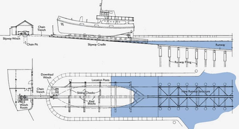
Now that I think about it, I swear I saw a photo somewhere of a winch cable in a trough with temporary railway sleepers covering it, but I've no idea where I saw it...
Found the place - it was Underfall Yard, Bristol. Can't find the photo still, but there's a very interesting virtual tour here - be warned - it has audio that cannot be muted once the tour starts (though you could mute the tab in your browser). You can virtually look around the entire site, including the aforementioned sleeper 'bridge' covering the chains for the slipway/winch.
Alternatively, it is just visible in this Flickr photo, and here's a diagram.-
1
-
-
54 minutes ago, Nick C said:
I'd imagine the cable would just be run across the rails when needed. Looking around at a few on NLS/Britain from above there are plenty of slips (most, in fact) that don't have a winch shed at the top, so they must've either had a portable winch or run a cable across from somewhere else across the hardstanding. A few do have a capstan marked, so that might be a clue, while most of the ones I can find associated with boatbuilding yards have a big shed at the top (in which, presumably, the boats are built...). I can't find any with a siding across though, that must just be a figment of my imagination...
Indeed, there doesn't seem to be much of a precedent for running a track in front of a winch, but this one at Sheerness had two winches with a track behind it. There does seem to be something connecting the winches to a shed behind, but I've no idea what that is; it can't be a cable for the winch. Now that I think about it, I swear I saw a photo somewhere of a winch cable in a trough with temporary railway sleepers covering it, but I've no idea where I saw it, and I don't seem to have saved the photo like I thought I had.
@petethemole's (I hope you don't mind me resharing this one) photos (now gone due to the server crash, but thankfully I saved local copies) from the first entry in this blog show such a channel in the concrete:
All of what you see in the photo above will be in the final layout, and, although the brick building has been moved and modified from the original, it is still on the plan (labelled 'store').54 minutes ago, Nick C said:It's not as hard as you might think (though I've only done it with bullhead - there'll be a lot more filing with code 100), especially for industrial track where most of the sleepers will be buried under hardstanding or grot. If you've done flat crossings then you've already done the hard bit - the common crossing with it's various checkrails and flangeways. I wouldn't try a three-way as a beginner though, use Peco for that!
It's even easier if you use the British Finescale kits, but they're all bullhead...
That's useful to know, thank you. It's a shame PECO haven't got a three-way in their new bullhead range, as I might otherwise be tempted. I may live to regret this, but I think I'll carry on, at least for the time being, to continue using standard PECO code 100 trackwork (with exception of the 2 crossings). The majority of the track will be infilled anyway, so hopefully it won't look too coarse once painted/weathered.24 minutes ago, phil_sutters said:The width of the river and its curvature needs to suit the type of vessels that pass along it.
Absolutely. Like I said, the river traffic 'north' (up) of the bridge would be small river boats; nothing particularly big at all. However, I will endeavour to at least widen the river slightly, if not find a way to reduce the curvature a touch.
Thanks for your continued support, chaps!-
1
-
-
Thanks for this, Nick. I'll address your suggestions in turn:
47 minutes ago, Nick C said:I'd be tempted to move the loco shed slightly away from the workshop, to avoid the awkward sharp curve to get around the end of the traverser. Or perhaps swap the loco shed to the siding in front of the Nissen hut,
I agree it is a little bit of a tight turn. One thing I will say in its defence is that it is only really meant to be used for the Ruston 48DS - there are no coaling or water facilities for steam locos, for example. I suppose you could see a class 04 diesel, but to all intents and purposes it wasn't really designed for mainline locos to use the loco shed, nor the traverser.
I don't think there is room there to adjust its position, so the loco shed would have to move, as you say, to another siding - you mention the nissen hut siding, but I was also tempted to put it by the swing bridge as a sort of view blocker. An earlier plan did actually have provision for a tall shed for a steam crane in a similar spot.
47 minutes ago, Nick C said:and have what's currently the loco siding instead going across the top of the slipway, between it and the winch shed? - that'd allow delivery of materials directly to the slip.
With regards to putting a siding across the winch shed, I'm not sure how that would work. Presumably the winch cable would need to be fed under the track in a channel?
47 minutes ago, Nick C said:Have you considered using some hand-made trackwork? That'd allow you to adjust the geometry of the pointwork more to make it flow better, for example where the line comes in from the swing bridge to the loop point, and the siding leading to the traverser.
Hand-made trackwork - this is indeed something I had considered (I was instead expecting someone would comment on the fact I'll be using Code 100 - I've got a bunch of medium points and flexitrack leftover from a failed project!). The two flat crossings would indeed be 'scratchbuilt' - I've done it in 009 so I should be able to do it in OO gauge. The thought of making points however scares the daylights out of me! Yet, it is something recently that has intrigued me, I will admit. I may well be tempted, but it would be a huge undertaking; especially with a 3-way point needed! Though to be fair, you did say 'some' hand-built track...
47 minutes ago, Nick C said:You might also want to make the river a bit wider at the back - given the swing bridge, it's presumably navigable, so would need to be wide enough to keep a decent depth at low water.
Agreed; even if it is to be used for smaller river boats, it is very narrow. My original idea was to use forced perspective; both to suggest the scene is even deeper than it is, but also to get away with modelling a narrower channel. However, having the siding near the backscene at that particular point would rather ruin that illusion I suspect. I may have to slightly shorten that siding and quay, move the nissen hut to the right, and thus widen the river. Ideally, I'd chop a bit from the left bank, but the (very interesting) kiln needs the space.
Thanks again for your thoughts - that has given me something to mull over and 'play around with' on XtrkCAD.All the best,
Jamie -
3 minutes ago, Nick C said:
This one is good for Dibles Wharf: https://www.britainfromabove.org.uk/en/image/EAW020009
There's also a good map of it on the Southampton planning site: https://planningpublicaccess.southampton.gov.uk/online-applications/applicationDetails.do?activeTab=documents&keyVal=5600064FUL - along with quite a few other buildings in that area suitable for my early 50s period, many being listed as they're rebuilds or replacements for war-damaged buildings in the area.
Great finds; thank you, Nick!
I'm always checking the NFDC website for useful plans for other projects, but it didn't occur to me to do so on such websites for this project for some reason.
That should come in very handy...-
1
-


.jpg.3f238c2852042100ca6047d3149e9d64.jpg)
Sandy Shores - My first proper go at painting/detailing a locomotive!
in Sandy Shores - A sunbleached seaside railway
A blog by SouthernRegionSteam in RMweb Blogs
Posted
Hi Martyn,
Many thanks!
Considering a few months ago I wouldn't have had the courage to repaint a RTR model, I'm really pleased I had a go - and I think the results have been much better than I expected!
You're not the first person to say that Mikkel, and that makes me a very happy chappy; as @Neil's layouts have always been a huge source of inspiration - especially Little Point. If memory serves me right - that layout was the reason I decided to build the trestle for the headshunt, which is one of the stand-out features on the layout, in my opinion.