


Fen End Pit
-
Posts
858 -
Joined
-
Last visited
Content Type
Profiles
Forums
Blogs
Gallery
Events
Exhibition Layout Details
Store
Blog Comments posted by Fen End Pit
-
-
The anycubic slicer has profiles for lots of resins. It is just that chitubox doesn't yet know about the m5s pro yet and I am used to using it to do support positioning. What I have worked out is that I use chitubox to do that then export the models with support as an stl. Then take that it the anycubic slicer and slice and print from there.
David
-
5 hours ago, barrowroad said:
David, As a former Weights & Measures Inspector I would describe your lovely model as suitable for a platform weighing machine rather than a weighbridge. The calibrated weighing beams for a weighbridge were much longer than the one you have modelled. The Lavenham Goods photo is of a 'sunken' platform machine probably of up to a couple of tons capacity. Weighbridges were usually 10tons or over.
Robin
Roy's model on the Crownest tramway was obviously meant for weighing little narrow gauge 'tubs'. I would expect that these would have fitted within your 'couple of tons' specification.
Thanks
David
-
On 17/01/2024 at 16:58, Keith Turbutt said:
Hi David,
Looks like the one in Lavenham Goods shed. See also my PM

Thanks Keith,
A lovely photo. I think that it is slightly taller than the version Roy modeled, the plinth looks a bit longer and thinner.
I'm intrigued by what looks like a stretcher frame in the background?
David
-
Nice relaxing, inexpensive build? You can change that be adding the most complex shaped load manufactured from purest gold.
David
-
 1
1
-
 1
1
-
-
16 hours ago, Portchullin Tatty said:
David
Markits do (or at least did) produce a P4 axle?
I use them and a set of Markit wheels during the chassis builds as the self quartering function takes one of the unknowns away during a build. It means that you only ever need to put the Gibson (or other) wheels on once at the end of the build.
Mark
Yes they do, but they only seem to be available direct from Markits and not through the various resellers like Wizard or Roxey. I will try to get some as they might make this easier.
David
-
On 29/07/2023 at 13:47, brossard said:
Very innovative wheel design. I tried EM some while ago but I absolutely have no faith in non self quartering wheels such as Gibson or Ultrascale. I did try Markits, which I do trust but couldn't get things to work. Happily I discovered 0 gauge and everything is now right with the world.
You are doing a great job with this kit development. Watching with interest.
John
Gibson and Ultrascale wheel are fine normally, particularly if you have a GW wheel press. It was just the resin centres which didn't have the grippiness of the plastic.
David
-
On 16/07/2023 at 22:41, Portchullin Tatty said:
Have you thought about making the tender body as an etch, there is a depression where the coal slope is and I would suggest you need the thinness but also robustness of the brass to make a durable but convincing tender flair?
One of the hardest bits with the PDK kits for ex-GER locomotives is the tender flairs. The 3D print comes out pretty well and slight line you see on the photo cleans up quite easily. As to the robustness the 3D print I have on my first J17 is still looking good after being hauled around and shown to various people. I have had the footsteps break off with heavy handling but stick back on with superglue.
David
-
 2
2
-
-
2 hours ago, stewartingram said:
I have a VERY old Bec J17 (warts & all) which was running on a Triang (?) chassis complete with X04 and shiny oHrnby wheels. Last year I got a new SEF 0-6-0 etched chassis, Markits wheels, HL gearbox, and a CCT motor. Basic construction of the chassis was completed, still got the details to fit but it got sidelined, I'm on the verge of restarting it. Being aware of the 'stretched' shortcomings of the body, I'd love something better, your version looks good (though not sure about taking on the wheels?). I'm following this with interest, but the old 'Bec' will also survive all this, it's in its 'forever' home just like a pet cat!
I see Markits do a 4'9" 15 spoke wheel which would probably be fine in EM or OO. The frames I have designed fold up to be a suitable width for P4 but I've included spacers on the etch which can be used if you need something narrower.
David
-
1
-
 1
1
-
-
2 hours ago, Malcolm Cudmore said:
Hi Dave, it was good to meet you at Beccles last weekend. And excellent to see Fen End Pit “in the flesh”. I wonder if you could remind me of the 3D printer and software you mentioned. As a reminder, I was showing Wainford Siding upstairs next to Alan. Thanks. M.
Hi Malcolm
It was good to meet you too..
I have a Phrozen Sonic 4K. (there is an 8K coming soon for ~£300)
Typically I'm using Onshape for my 3D CAD drawing. It is available for non-commercial hobbyist use.
Hope that helps
David
-
6 hours ago, tanatvalley said:
Superb video, very enjoyable.
What is your mortar mix and how do you apply it?
Thanks
Alan
I use Wilco smooth surface interior filler, I add a little water and wipe it over the brickwork and then wipe it off. I then final wash over the wall with Vallejo grey wash.
David
-
 1
1
-
-
7 hours ago, signal eng said:
Superb, enjoyed that. Full of GE and East Anglian atmosphere. Loved the bit by the river and LX. The camera looks ideal. Any idea of the make or source?
Jerry
Glad you enjoyed it. I'm sorry I have no details on the camera, it came from China and, while it has 'Sports DV' and 'UKK@SXA1705S' on the box, that doesn't bring up anything on Google.
David
-
1
-
-

Ok, here is an 'out there' suggestion. Could Bodmin north just be a single sector plate which turned to allow access to/from either the Bodmin General fiddleyard or even, by a hidden line along the back to the Wadebridge cassette board? It almost looks like from the plan you could get a 4' radius curve and turn the Bodmin north yard to be parallel to the end wall. My minimum radius on Clare is down to 3'4" off-scene going into the fiddleyards and I have no problems which my P4 stock which includes some pretty long wheelbase locos like B1's and J20's.
David
-
A fascinating location. What shape is the man-cave? Is the intention to place the layout against a wall? Might it be better to straighten out the rear right fiddleyard even if the straighten out results in the overall length being slightly more? I found the process of getting the layout I wanted to built to fit into the room I had in a way which was going to be something I wanted to live with something that took a lot of time. It was very easy to draw a plan which would go into the man cave but it is harder to consider what else you want to be able to do in the man cave and consider whether, in the future, you may wish you'd built the grand scheme slightly differently.
David
-
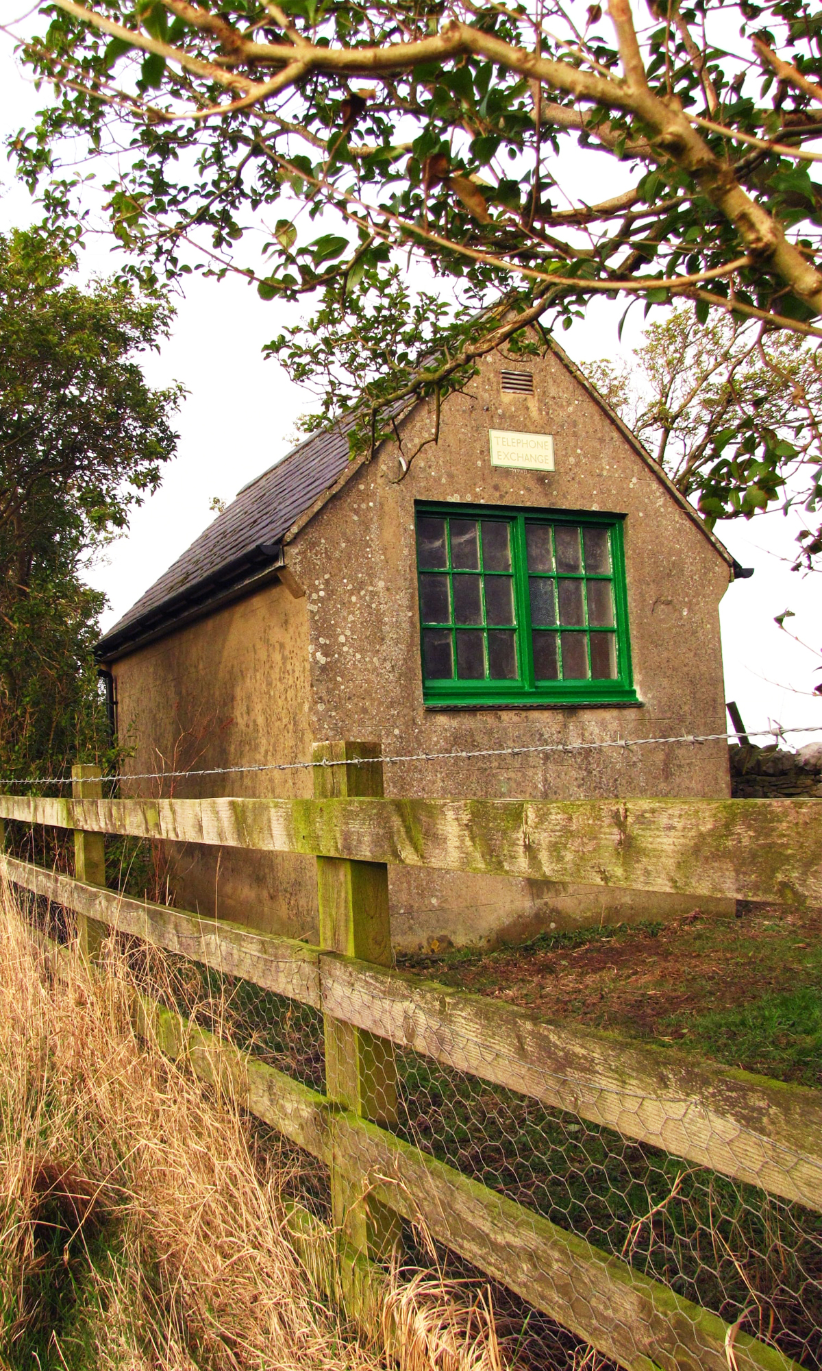
13 hours ago, uax6 said:
Your telephone exchange buildings are quite easy... The pitched roof one is an A type building, that probably housed a UAX5 or a UAX12. The hipped building is a B type and would have been built for the replacement exchange, probably a UAX13 (although it could have been a UAX6).
Your later colour photo of the exchange shows that the B type has been extended over the footprint of the A type building, in this case at least twice, if not three times! I'm guess the original B type is actually the 1/4 that is behind the tree, and its actually been extended forward and backwards, and lost the hipped roof in the process.
Andy G
Thanks Andy, that is really helpful.
I've been searching online and I'm guessing that the A type would be something like this I found on Twitter
while the B type was like this (only not rendered)
Does anyone know of a site with any plans for these and where they generally a standard size and layout?
Actually I've found two better examples - Glemsford, not far from Clare in Suffolk
and Bures
and Felsted
Yeh! another research rabbit hole to dive down!
and now I've found some plans from where someone was refused permission to turn one in Oxfordshire into a house.
David
-
1
-
-
17 hours ago, Western Star said:
Good day Dave and thank you for your informative response to my questions.
A further question please. The first photo of the three (tilted) wagons suggests that the raft is not flat or at least the edges are wavy, what is the cause of this distortion?
Asking Qs because Son has started 3D printing with an Anycubic Photon Mono using resin from 3D Jake, the learning curve is likely to be steep and reading topics such as yours are helpful.
regards, Graham
Hi Graham
The bottom of the raft which is provided by Chitubox has sloped edges so that you can get a scraper under them to lever the part of the bed. There is a tendency for the face of the model pointing towards the bed to be a little wavy. This is because of the resin pulling away from the top of the supports and, occasionally, from uncured resin pooling amongst the supports and not getting washed out enough with IPA after printing before you cure. Designing your parts so that there is a flat or easily sandable surface facing the bed is usually a good idea. There is always a balancing act between too many supports and so too much clean up and not enough supports and a deformed/failed print. I usually err on the side of too many supports and facing having to remove more little legs over just getting a failed print.
hope that helps
David
-
1
-
-
On 01/04/2022 at 09:06, Western Star said:
What made you think that tilting the print was necessary?
Similarly, what prompted the hole in the wagon floor?
regards, Graham
Resin 3D printing is about a battle between the resin sticking to the already printed model and staying stuck to the transparent FEP plastic that forms the bottom of the resin tray. If the cured resin sticks better to the vat than it does to the model then your print fails. A large flat surface area like the bottom of a wagon is quite likely to just stay stuck to the bottom of the printer. By tilting by a few degrees the flat bottom is printed in smaller sections and much more likely to work.
Similarly if you print what is in effect a sealed box then you air pressure can prevent the box from pulling away from the FEP. I added a small hole in the base of the box so that air could get into the sealed box and allow the printer to lift the wagon body off the FEP. I'm not sure if it was strictly necessary but it didn't hurt.
David
-
1
-
-

That is coming along nicely, the axleboxes look particularly good.
Good luck with it.
David
-
1
-
-
I wouldn't have thought so. The mashima's are better suited to a traditional worm gear arrangement. I think the secret to most of the Simplex/Ruston's is to use delrin chain drive. On the Simplex I think an N20 driving both axles via chains would be worth a try.
David
-
16 minutes ago, Fang said:
How does the N20 motor perform? Thinking of using one (or an N30) in a 16mm Simplex
It's not bad, the first ones I had were too higher gear ratio but I was after slow running. Ultimately you are not going to get as smoother running as with a decide Mashima or whatever from High Level which would have cost 10 times the price but you pays your money and takes your chose. There is quite a whine if rev'ed too hard but I'm pretty happy overall.
David
-
3 hours ago, chrismears said:
This is such a fantastic project. These last few days I've really enjoyed reading and rereading through your posts and learning how the models were built. I'm starting to wade into 16mm and scratchbuilding my own Ruston based on some drawings from the Merioneth Railway Society's drawings for a Ruston 16hp. I'm "moving up" from the much smaller scales and since my model is for indoors use think track power is still the way to go. That's a rambling way of my asking what you are using for wheels under this model?
I'm looking for a 20mm diameter wheel for my model. You mention using O scale wheels and I like their shape/profile so don't mind adopting that in place of an actual 16mm scale wheel. I'd like it in metal.What you're using look exactly like what I'm after. I know it's been a very long time since you wrote this post but I thought I'd ask anyway.
Chris
Hi Chris
I'm pretty sure that the wheels were just Alan Gibson 7mm scale 3' diameter wagon wheels. They work out at 21mm but close enough. For my Binnie skips I use Alan Gibson Lowmac wheels.
Glad you're liking the blog posts...
David
-
I was able to roll out one row of stones and then butt up the second row against it. There was a little bit of manual scribing to join the two rows together but it was surprising easy. Sculptamold is wonderful stuff for this kind of work, you had about 10 minutes of working time which was perfectly adequate.
David
-

I've not had a problem using multi-cored wire from old Cat-5 cabling with CBUS myself. It is great to move on from the CBUS test plank to actual implementation on layout where all the advantages of using a LCB actually come into their own.
Well done.
David
-

That is coming along very nicely - and your fingers only show slight signs of damage!
David
-
32 minutes ago, f1xer said:
I'm a great fan of the WR5 so I think you've done a great build. I have an SM32 WR5 which I built in metal/tin and using mamod wheels (yes slightly oversize). Not quite as much detail as yours however I managed to get a lipo and remote control in the battery box. Like you I have the motor and gearbox in the chassis. I'm considering building one for 5" gauge and the Tilston plans you mentioned would be incredibly useful but I haven't been able to make contact either.
 I'll be interested to see your WR5 painted/weathered or whatever you plan to do with it next. Good luck.
I found some of the drawings are on flickr. Hope that helps.
https://www.flickr.com/photos/jaytilston/3263186180 and https://www.flickr.com/photos/jaytilston/3263195550/in/photostream/
If you go through the whole photo-stream there are some nice detail photographs too.
David


 I'll be interested to see your WR5 painted/weathered or whatever you plan to do with it next. Good luck.
Little Grey Fergie
in Fen End Pit's Blog
A blog by Fen End Pit in RMweb Blogs
Posted
As observed I got the tyres on the wrong way around. Try this...