


Stoker
-
Posts
379 -
Joined
-
Last visited
Content Type
Profiles
Forums
Blogs
Gallery
Events
Exhibition Layout Details
Store
Blog Comments posted by Stoker
-
-
Your blog entry strikes me as being somewhat more a passive-aggressive rant than a question, as your title would suggest. Yes people moan and often they're wrong, yes manufacturers sometimes get it wrong, yes detail is better now than it was previously. I don't see what point you're making. I know it's infuriating, I got told off for speaking out against it in the thread for the Beattie Well Tank, but it seems like it's something we're going to have to live with. Given that our hobby is stereotypically overrun by grumbling old grumpy gits in loveless marriages perhaps we should've come to expect it by now?

The only thing I feel I can respond to is perhaps your mention of people who complain that models are getting too fragile to handle. I also find this to be the case, mainly from my experience of North American models. Yes I know, the US scene is terribly, terribly boring, but I went through a phase of liking it, and found like most other dabblers that it's mostly due to the materials used, rather than a lack of care. Handrails, "grab irons", and most other thin railings etc. are made from this semi-flexible material that likes to snap, sometimes just because of temperature changes, or because it's been bent one too many times.
Since the UK scene has largely followed the US, Germany and Japan, a lot of these technologies have been adopted but not improved. This is a major frustration for those of us who have been happy to see US manufacturing standards come to the UK, only to find that parts of their £100 model are breaking because lessons haven't been learned.
Best,
Scott.
-

Been a while since I've modeled US outline, lets see if I can remember some of the faux pas.
A grain elevator.
A "ranch".
A walthers gravel/cement/coal industry.
Emergency response vehicles.
A demolished/burning building.
A church with a wedding.
Road works.
Haunted house/graveyard.
Very few people execute the whole grain elevator thing very well, but I remember there was this one guy who did an amazing job, and set his layout in autumn to boot. Rust stained weather beaten grain elevators against fall colours is a pretty tall order and he managed to not only pull it off but set a real nice atmosphere going. I think so long as you do it "right" you can pull off anything - fire trucks are no exception, and yours does look great.
-
This is looking really good. Tracks in hard-standing is challenging to model accurately but your technique seems to have done quite well.
I'm glad to see you're still gradually working away on this layout.
Scott.
-
Thanks Scott...it's on the shopping list...for now I will continue with the evergreen...having bought 2 new packs the other day...that should see the dries complete.
Agreed...it's been a struggle...but sometimes the circle has to be completed to find the right solution and now I just have to complete the shell so I can begin the (hopefully) painless stone cladding on the other building.
Agreed. I've probably gone through just about every single method now and it's still not perfect. Even though the ratio sheets are great, they're no good for windows, because the plastic is too thick. So I mainly only use it for roofs and windowless walls.
Ratio, in the same product line as the corrugated sheets, do some good stone sheets, probably the best I've seen in N for doing Cornish stonework. Good luck with it anyway.
Regards,
Scott.
-
For the sake of your sanity in future, may I recommend this product?
http://www.mikronmod...orrugated-Sheet
I now use this for all my corrugated structures in N. It's great stuff, takes a while to learn the tricks of using it, but once you get the hang of lining up the sheets the detail is excellent. Don't get me wrong though, what you've done so far does look great, but I think you're going to have to move past this cladding stage fairly soon before you start to get fed up with this project. Hence why I'm suggesting something that has done the overlaps for you.
However, I am relieved to see that you've decided to just go along with horizontal strips, rather than attempting to apply the cladding in prototypical individual sheets. Believe me once you've weathered it, you won't notice any mistakes or lack of detail - and it's so small anyway that it's not exactly like it stands out. We're talking a tenth of a millimeter detail depth of overlapped sheets. That's shallower than a coat of paint, and quite simply just wouldn't be visible to the naked eye.
Regards,
Scott.
-
I would personally hate to see what would happen to an aluminium bodied hopper once 10 tons of coal has been dropped from 20 feet down into it. I imagine that it would at least be a rather different shape afterwards!
Scott.
-
Um Scott
Arent CDA and HAA hopper bodies aluminium? I dont think they rust.
Might be wrong though
Cheers
Jim
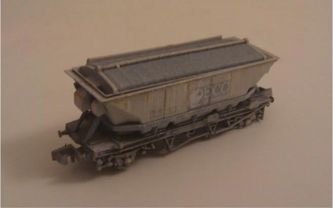
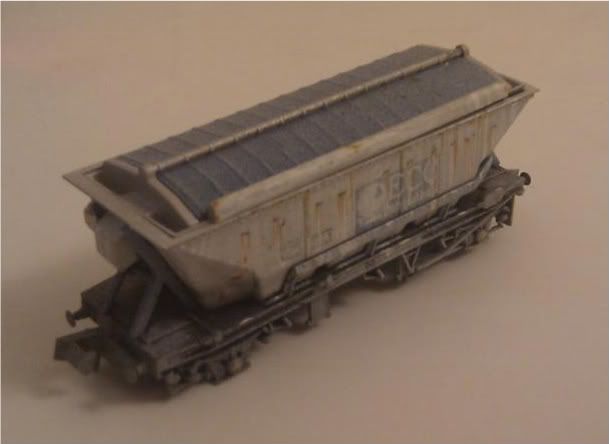
They are actually galvanised steel. CDA's are in a constant state of flux, getting sandblasted, repainted, covered in clay dust, rained on, covered again, rained on again, etc. and I have got many many photographs of rusty CDAs.
By the way Pete I didn't take your post as being arrogant at all. I fully understand that every modeller has his priorities when it comes to making compromises. My priorities are with the clay works themselves, as that's what my interest revolves around.
The OOV is indeed a mevagissey model. It's woefully inaccurate however.
Scott.
-
 ">
"> ">
"> ">
">Also, I've diagrammed one of your photographs, to point out some specific details on the exterior of the drying plant.
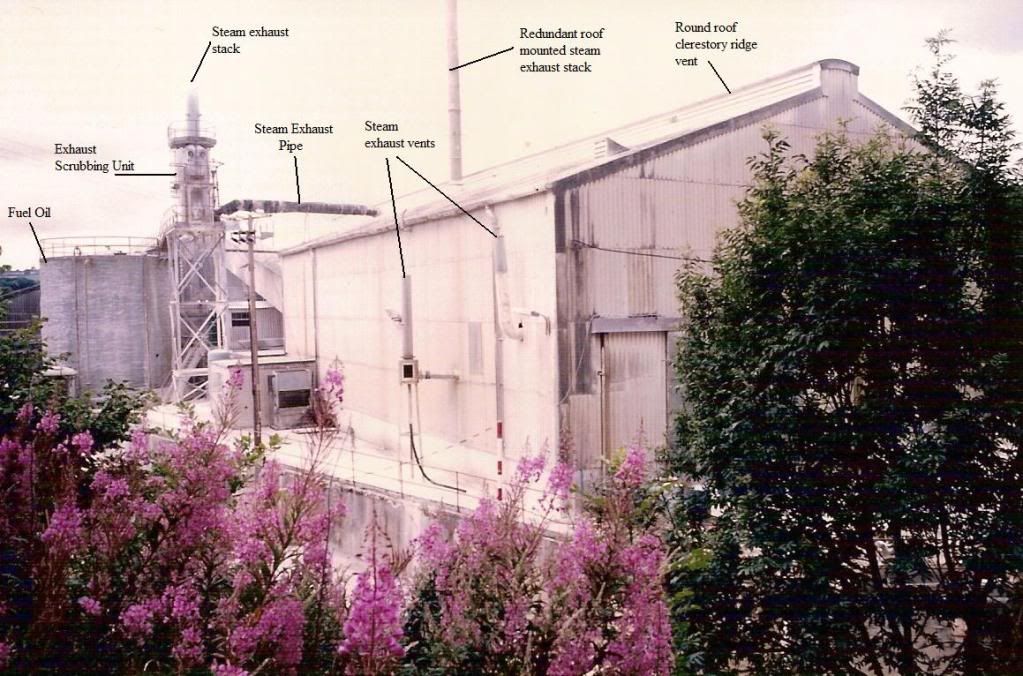 ">
">The two steam exhaust vents toward the end of the building were placed there because at this end of the building the clay discharged from the rotary dryer, and was still boiling hot. Without them the building would literally fill with steam and clay particles, which would "snow" down onto all the equipment inside.
Once again I hope I've been of some help and of course if you've got any questions, get straight in touch.

Regards,
Scott.
-
Hello again Pete!
From looking at your photographs I think what's really stuffed you in terms of length is that the buildings are at an angle compared to the baseboard. Is there any reason why the baseboard itself can't go off at an angle, to follow the direction of the tracks? I'm assuming you've got a very good reason for making the boards as narrow as they are, but since you appear to be doing them in modular sections I just wondered if perhaps that would make your life a lot easier, if it isn't already a bit late?
I have to take a diversion though, from your thoughts, along with everyone elses, on the necessity of modelling every single overlap on every single sheet of corrugated! You've got a vast amount of building to cover, and honestly it's a waste of time because even in real life at those distances (if you were a scale 100 feet away from the building you'd still only be 20cm away from bumping your nose into the building) it's not visible. Corrugated fibrocement sheets used in the clay industry are a mere 6mm thick, and have a single corrugation overlap, meaning that from a distance none of the vertical overlaps are visible, and sometimes even the horizontal overlaps are difficult to make out. They got lost among all the corrugations. In the vast majority of my photographs, except those taken by VERY high resolution digital cameras, it is impossible to see any overlaps at all, except the horizontal ones.
Personally, I use ratio accessories N gauge corrugated sheet, 4 packs of 75mm wide x 90mm high corrugated sheets pre-moulded with overlaps at 7 scale foot intervals. Looks fine, and it's easy to use.
I would suggest that if you are going to spend time ripping things apart and redoing them, I'd spend it making the buildings scale length, as I'd imagine that the construction paper you're using is a lot cheaper than the cladding!
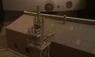
Anyway, as promised, here are some photographs of my rotary dryer building, based more on ECLP design protocols rather than any specific building, but taking design elements from Blackpool, Treviscoe, Trelavour, Wenford, and Moorswater. The building is currently unfinished. Coins and a ruler have been added for scale.
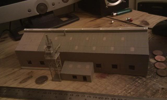
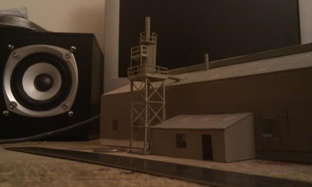 ">
">The steam exhaust system was a ###### to build. The prototype exhaust scrubbing unit has a system of pipes around the outside, which carry the liquid sprayed under pressure into the chamber. This liquid is intended to capture dust particles and neutralise sulphur dioxide emissions. I was originally intending on modelling these pipes, however it proved to be so fiddly and tiny that I gave up in the end and just left it without. I have still got to figure out how to do the safety caged ladders! The safety railings around the platforms are plastruct, however I think I would probably have been better off finding a brass alternative as the plastic is a tad thick. Nevertheless it looks fine as it is.
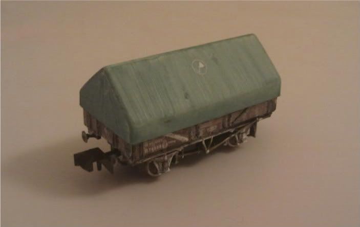
Also, some of my weathering on a CDA and an OOV. The cat attacked the CDA a while ago, so it's missing some wheels and other bits!
-
When I get around to it I'll produce some scale drawings. I've (partly) built an N scale model of a rotary dryer building, albeit a different prototype, so I could upload a few photographs to give you some ideas about the steam exhaust system.
The covered conveyor would be difficult for you to model at this stage, unless you made some serious modifications to the structure. If you would like to be as prototypical as possible, and want to include this feature, then my suggestion would be to hold fire on the cladding for now, and wait for me to send you some diagrams, as it's easier to show than tell.
-
Got some information for you that you might find useful. I have been studying and modelling the china clay industry in Cornwall for the past 6 years, so if you can think of anything you'd like to ask me, please go right ahead.
First of all, I noticed in one of your previous postings that you pointed out the tall cylindrical structure as being the rotary dryer. Actually, this structure is the fuel oil tank for the dryer, the rotary dryer itself is a mechanical plant sited within the building that you are currently cladding. It is an approximately 7 meter by 2 meter insulated tube, laid horizontally, and slightly inclined to one end, mounted on rollers. This tube rotates, hence the term "rotary", by a planetary rack and pinion gear, and accounts for just under half the length of the building, and about a third of the width. The other half is taken up by the filter press deck, where clay slurry is introduced under pressure into banks of filter cells. This produces a more easily handled "cake", which can be moved throughout the rest of the process on conveyor belts. The remaining space inside the building is taken up with machines like lump-breakers, pug mill extruders, pelletisers, paddle mixers, feed delivery conveyors, and inspection platforms. Your open sliding "door" at the end of the rotary dryer building, would be looking in on the steps up to the press deck, and their concrete supports.
Secondly, I noticed that you have provided the entire length of the building with an asymmetrical roof. On the prototype, this asymmetrical roof only extends half-way along the length of the building. At this halfway point, a covered conveyor structure emerges and rises to join the gable end of the large clay store. This feature is visible from photographs. The rotary dryer building at moorswater is 50 feet wide x 160 feet long, of which the first 90 feet has an asymmetrical roof. The asymmetrical section is about 6 feet wider than the symmetrical section, accounting for the 6 foot wide covered conveyor belt structure. This structure contains a single conveyor belt, and a walkway next to it.
Also, the individual corrugated sheets used on buildings built by ECLP, were generally 7 foot x 3 foot. Don't forget that corrugated clear plastic sheets were used on the roof to allow light to enter the building. These were laid in a distinctive alternating pattern. Toward the end of the dryer's life, a few of these got broken and were replaced, resulting in a pattern of different coloured sheets on the roof. The plastic became so brittle in the constant sunlight that eventually all it took to break one was to lift a ladder or pipe too high! Speaking of the roof, it appears that you have already noticed that there is a clerestory ridge vent on the rotary dryer building. There is also a similar vent on the store building.
Another feature, possibly yet to be included in your model, is the wet scrubbing exhaust stack unit. This stands atop a steel tower beside the rotary dryer buiding and the oil tank, and is visible in photographs of the site. This unit essentially consists of a vertical cylindrical tank with an exhaust stack emerging from it's top, and an exhaust steam pipe entering it's base. This feature was, I believe, added sometime around 1975, when dust pollution laws came into effect. Prior to that, there was just a vertical steam stack emerging from the roof of the rotary dryer building, about halfway down it's length, and just off-centre. Which of the two steam exhaust stacks are modelled would depend on your era, but either way the feature is essential to a modern dryer, as aside from water, steam and hot gasses are the main bi-product of mechanical clay drying. A steam exhaust stack is how a clay industry engineer can tell dryer buildings apart from store buildings without entering one.
The older dry has a cut-down granite chimney stack at the far end. This might be worth including on a painted backscene. The dry is approximately 50 feet wide, and in the region of 300 feet long. The settling tanks at the rear (the uphill side) of the dry, are about 70 feet by 60 feet. Among these settling tanks adjoining the back of the dry are some small buildings. These buildings were filter press houses, that were added to aid the dewatering process back when the coal fired dry was still in use. These buildings stand one storey above the settling tanks, and were 20 feet x 40 feet, with a gable roof. Access to these concrete block-built buildings was usually internal, so their only external feature should be some 5 foot square industrial 12 pane windows.
The modern rotary store is 115 foot wide, by 150 foot long, and is asymmetrical along it's entire length. The lower side covers the tracks. The ridge of the roof is 18 feet off centre. There are two catwalks either side of the ridge, the purpose of which is unknown.
To model all the buildings in N scale, in full length without the use of selective compression, would've required a board 60cm long, by 36cm wide, if you excluded the settling tanks on the coal fired dry. To model the entire length and width of the site, from boundary to boundary, would require a baseboard 1.6 meters long by 60 cm wide. Most of this would be taken up by settling tanks, access roads and the headshunt. As it stands I think your selective compression has worked very well, and the height of the buildings looks to be spot on to me.
Well anyway, I hope this wasn't too long to read, and that you got some useful information out of it. Like I said if there's anything else you want to know about the clay industry or Moorswater dryer, let me know.
Scott.
-
 1
1
-


1970's Plymouth Traffic
in MarshMills' Blog
A blog by MarshMills in RMweb Blogs
Posted
If it was Liskeard then it wouldn't have been rock. China clay, maybe, but not rock. To the best of my knowledge, quarried stone has not been transported on Cornish rails for an extremely long time. I know Serpentine in Cornwall is generally associated with the far west, Lizard peninsula.
I would imagine that various types of ferry fitted clay carrying van would be seen in the 70s.