


Darius43
-
Posts
4,497 -
Joined
-
Last visited
Content Type
Profiles
Forums
Blogs
Gallery
Events
Exhibition Layout Details
Store
Posts posted by Darius43
-
-
Still an excellent piece of work no matter how the couplers are fitted.
Many thanks - I'm really enjoying building this kit

Cheers
Darius
-
Well done. I noticed the kadee couplers between the bogies of the leading motor coach and 1st trailer, good idea as they are less likely to come apart. I would remove the curved dropper bar from the couplers as that will minimise the risk of them catching on points.
I had that happen on my 6 car pullman unit I mentioned earlier today. 1 of the couplers mounted at 1 of the cab ends of the unit caught a Y point and derailed the driving coach completely. After that I started removing the dropper bar from all my kadees and have not had anymore derailments.
I have already trimmed most of the Kadee coupler drop bars apart from one you see in the photo, which is in the NEM pocket that slots into the Bachman motor bogie and sits a wee bit lower than the other Kadees. The others are in the Kadee "black boxes" and are screw-fixed to the bogies.
Cheers
Darius
-
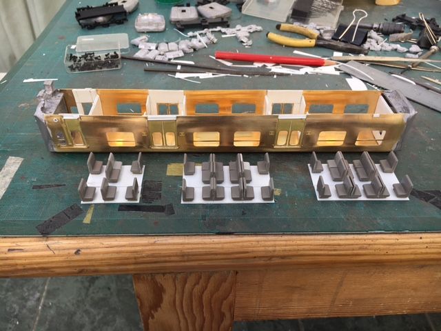
Seats added to motor coach and first trailer coach chassis completed.


Cheers
Darius
-
 2
2
-
-
The cast metal mounting block that Bachmann use for their DMU motors provides a decent amount of weight directly over the motor bogie. So far it has had no problems pushing and pulling itself and the other driving car under DCC at low speed. The test track at home is only 4 feet long so high speed running is not an option (or advisable as there is a three foot drop at the end ).However, as the unit being built in this thread will not have rubber tyres to add tractive effort, the whitemetal ends will do the job on the 508 that the rubber tyres do on my pullman unit and thus give the motors the added umpff they will need to make the 508 speed along on long sections between stops.
I also have some self adhesive tyre balancing weights that are useful if added mass is required.
Cheers
Darius
-
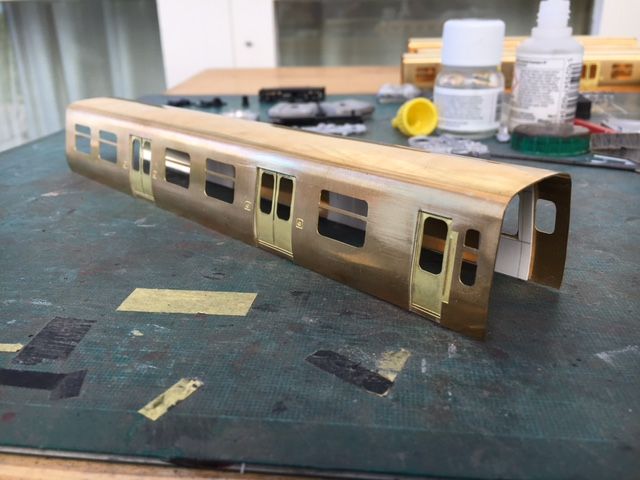
Second driving trailer bodyshell nearly finished - needs roof rainstrips and vents plus some body side details to be added. The shell is not fixed to the chassis yet- just popped it on to check the fit.
I also replaced the cylindrical tanks next to the bogies with new ones fashioned from plastic tube and card - the kit-supplied ones were too large in diameter and looked wrong.


Cheers
Darius
-
5
-
-
DCC harness and wires connected to circuit board - space left for possible connection of LED lights . Tested on DCC and works fine - hurrah!!!

Wires tidied up within depth of chassis.


Cheers
Darius
-
5
-
-
Added pickups and wired up the trailing bogie. Motor wired up and in place. Will solder wires to some circuit board in the centre of teh chassis and then attach a DCC harness to the board.


Cheers
Darius
-
2
-
-
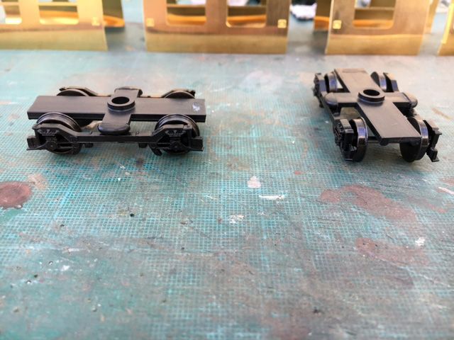
I m guessing that the bogie side frames came from a 15X DMU? You may want to consider removing the molding of the brake shoes as unlike the 15X the 508 would have had disc brakes.
Thanks Titan, I'll get the brake shoes removed.
Cheers
Darius
-
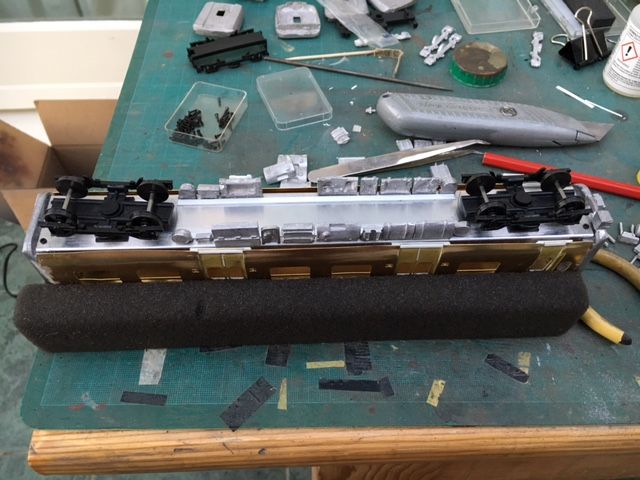
Started on the motor coach today using the motor from a Bachmann DMU (obained as a spare chassis from eBay - not wrecking a complete DMU for the motor).

The motor block and motor bogie are removed from the Bachman chassis.

DMU bogie sides removed and Class 508 bogie sides cemented in place. Other bogie assembled at the same time.


Hole for motor bogie cut in MTK aluminium chassis and chassis sides cut down by 1mm in motor location to get correct ride height. Plasticard strips cemented either side of hole to strengthen chassis and to provide a fixing point for the Bachmann motor block.


Cheers
Darius
-
2
-
-
I considered grafting the Piranha cab and end onto the MTK body shell but the profiles were different and I would need to saw 10mm of each end of the body shell.
That and having to butt join the resin cab ends made me persevere with the kit cast ends. Piranha is releasing the resin kit part by part so eventually there should be sufficient parts available to build a complete carriage.
Until that time there is this kit...
Our joint efforts should ensure that an RTR model appears before not too long
Cheers
Darius
-
3
-
-
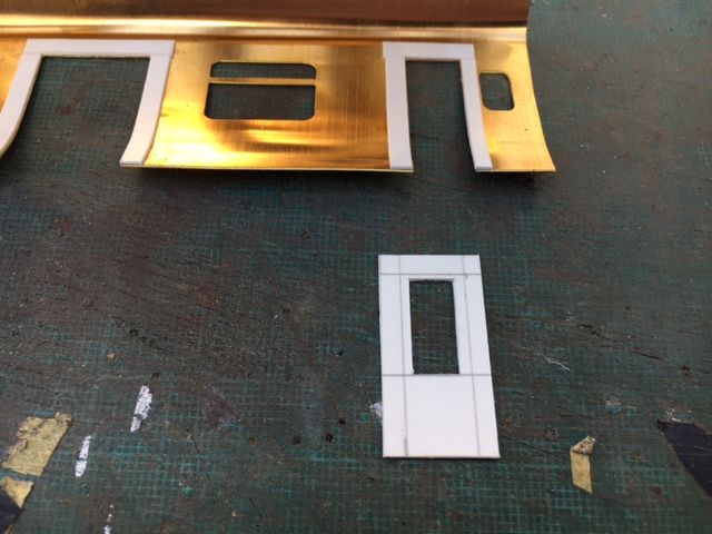
Made a start on an interior for the driving coach. A plasticard template was shaped (took two attempts) to create the door vestibule and carriage end partitions.
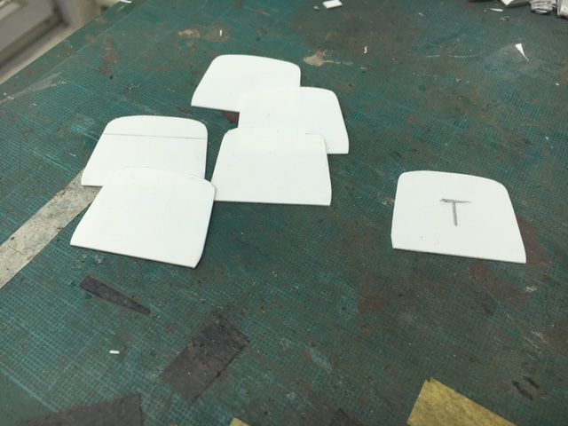
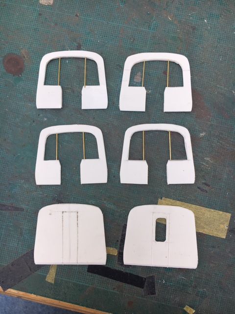
The template was used to make several more - each partition was laminated from two sheets for rigidity. The door vestibule partitions had the glazed and walk-through areas removed and brass wire used to form the grab rails. The coach end partitions had the doors scribed in place.
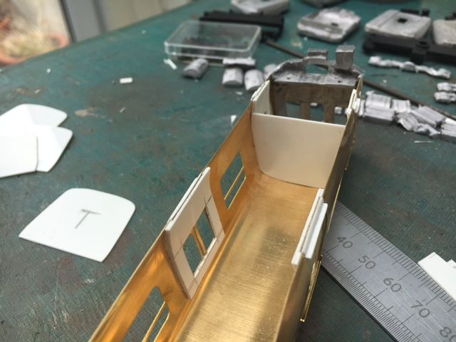
Partitions cemented in place - the door recess plastic helped reinforce this connection.
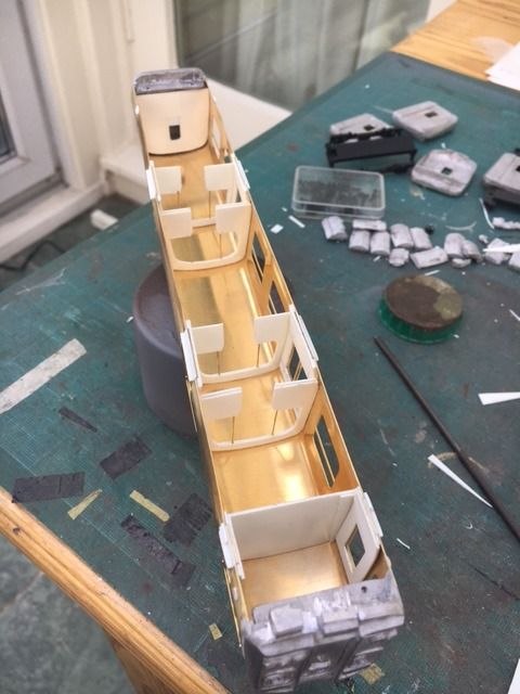
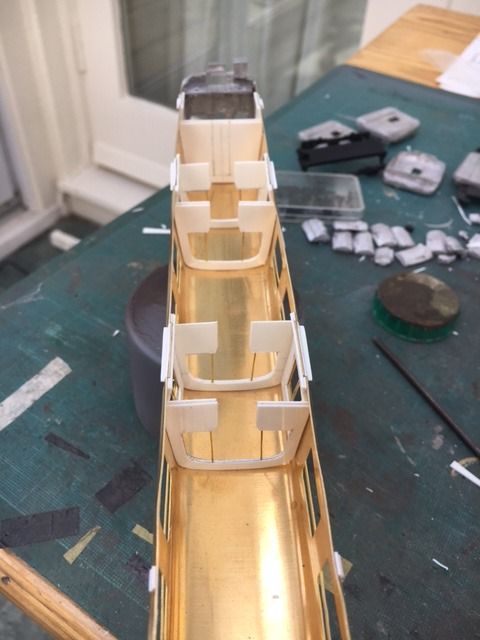
Floor and seating units constructed. I had one less seat than the prototype in order for people's legs to fit between the seats - I know space for people's legs and arms was not really a consideration in the full-sized trains but there is a limit to observation of the prototype.
As the floor width is wider at seating level than the gap at the base of the bodyshell (due to the tumblehome) the seating units were split lengthways so that they could be inserted without having to pry apart the boodyshell.
Cheers
Darius
-
3
-
-
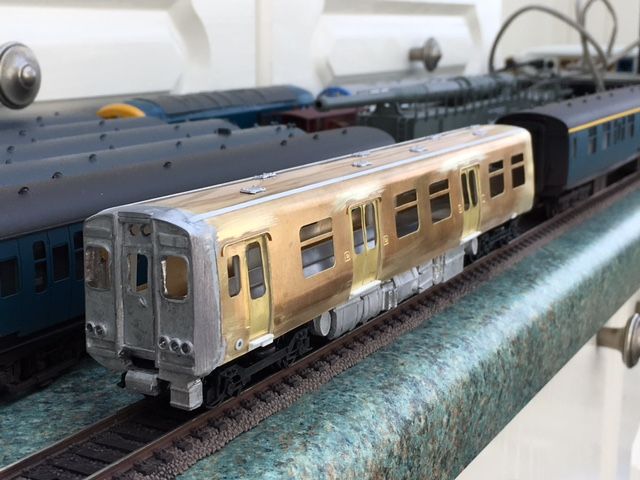
Rainstrips added using plasticard strips and kit-supplied brass wire. Kit white metal roof vents added. Plastcard doorsteps added.
Cheers
Darius
-
5
-
-
Thats vome on very quick and I agree it does look good.
I imagine that when it comes to powering the model that because of the combined weight of the 4 coaches that a powerful drive system will be required.
Haveyou had any thoughts on what drive will be used yet.
The kit came with a Black Beatle motor bogie but I plan to graft in the motor and motor bogie from a Bachman Class 108 DMU. I have done this for other DMU and EMU kits that I have built.
Cheers
Darius
-
Lowered
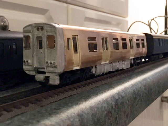
Cheers
Darius
-
7
-
-
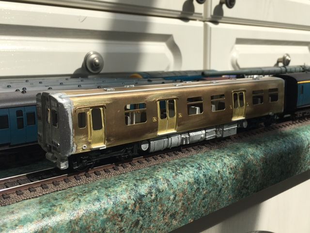
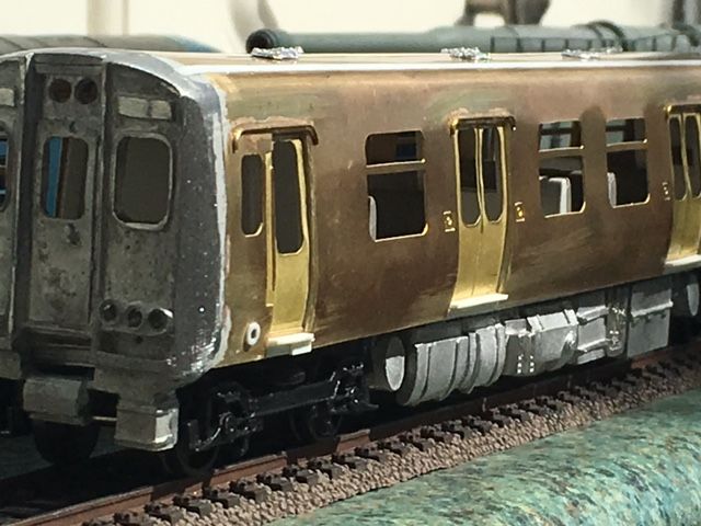
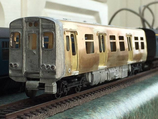
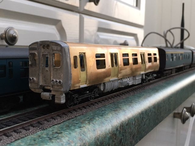
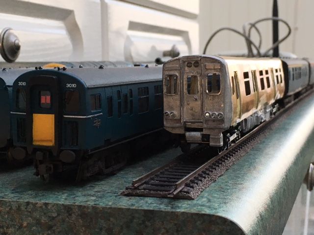
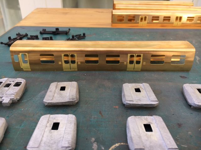
Great job so far Darius - I love the way you turn sows' ears into silk purses. Can I suggest that you check the ride height on the bogies though, as the 313/314/315/507/508 family were lower than standard coaching stock (I've seen 11ft 9ins quoted, compared to 12ft 9ins for Mk1 REP coaches like the one behind in your photo).
Looking forward to seeing the rest of the build.
David
Thanks David,
It should be simple to drop the ride height by a few mm. Looking at the roof profile compared to the Mk1 it could do with being lower to avoid loading gauge issues.
Cheers
Darius
-
2
-
-
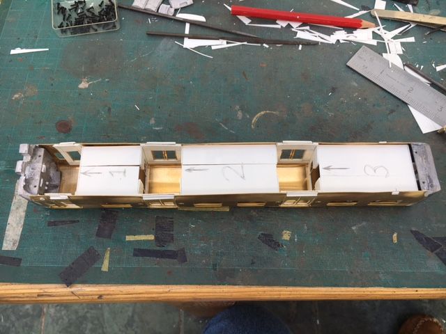
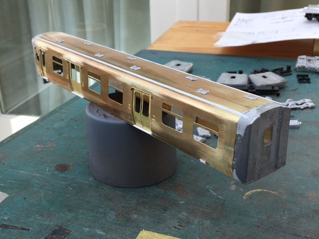
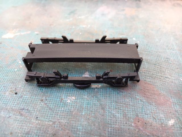
Started on the underframe using the pressed aluminim part supplied with the kit. I added plasticard layers to thicken the part to level it with the lower edges of the bodysides. Screw holes were drilled to enable it to be fixed to the "shelves" moulded with the cast whitemetal ends. The plastic bogie mounting parts were also screw-fixed to the chassis. I used plasticard pieces to thicken this area so the screws have a purchase.
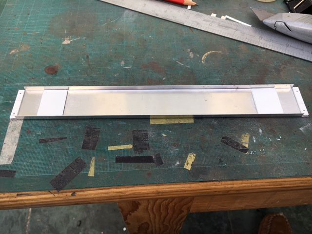
The kit-supplied underframe boxes etc. were cemented in place as per the instructions - most of them fitted. There is a random selection of bits for this but they are insufficient for the complete four-car train so some scratch building will be needed.
Cheers
Darius
-
5
-
-
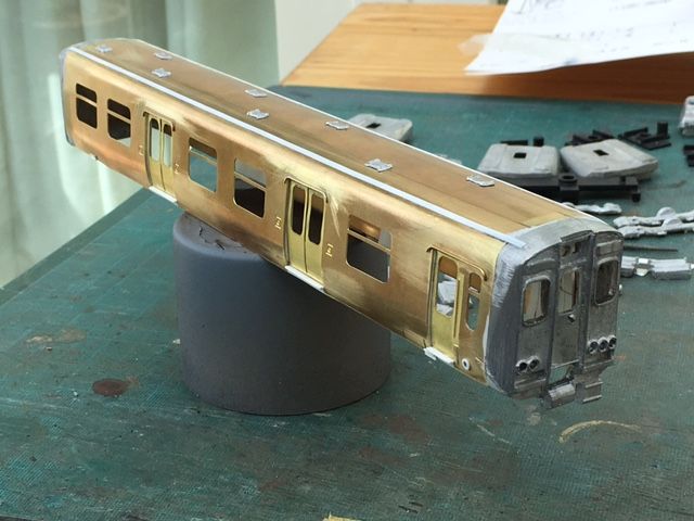
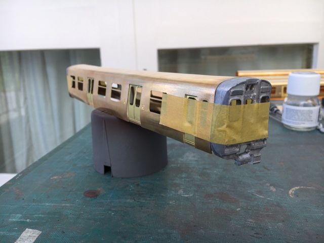
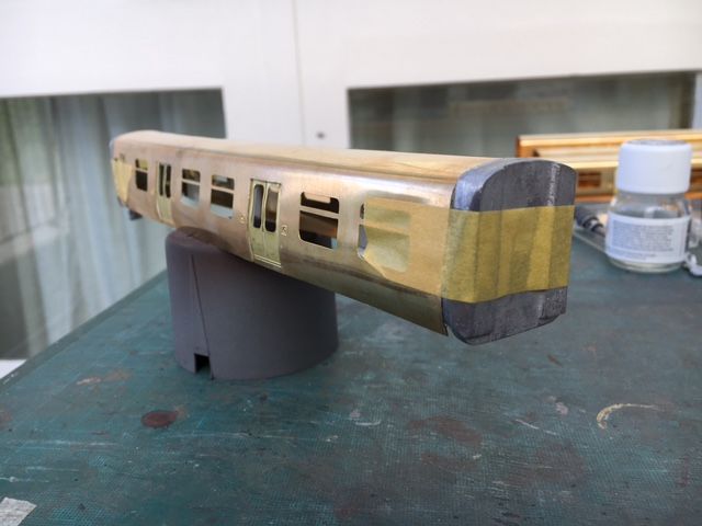
Plasticard strip used to create door recesses.
Brass doors cleaned up and cemented to plasticard recesses.
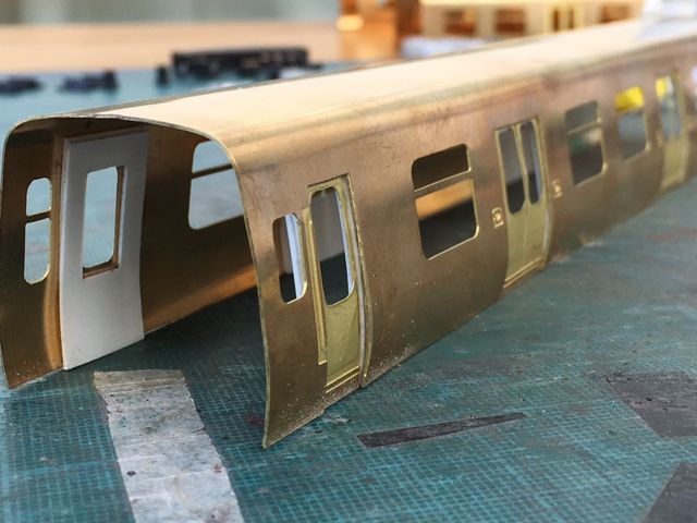
White metal cab and corridor connection ends fixed and will be left overnight to set. Will fill joints and then create a better-defined chamfer to the body ends. This is a distinctive characteristic of these units and the cast parts look a bit wishy washy in this area.
Cheers
Darius
-
6
-
-
Don't know if they would be useful, but somebody is selling 3D printed cabs on eBay which might complement the body sides more than the white metal ones?
I have seen and purchased these - they are resin casts of 3D printed parts. They look good but the profile (most likley correct) does not match that of the brass bodyshells. The eBay parts are the first in a series of parts to make a complete kit with the alter parts to follow.
I have decided to persevere with the NNK/MTK kit because I am an awkward sod

Cheers
Darius
-
2
-
-
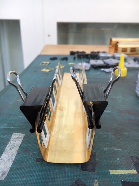
I thought about leaving the flush doors in place but it would have bothered me so I decided to cut them out and re-mount them inset from the main body. Sliding the bodyshell over the edge of the modelling table onto the cutting mat helped with this. The pre-curved tumblehome did flatten out a bit with this process but it was reasily re-profiled.
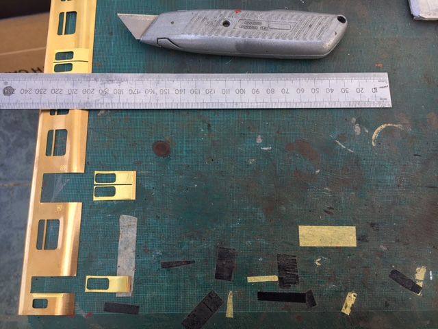
Only three more bodyshells to go

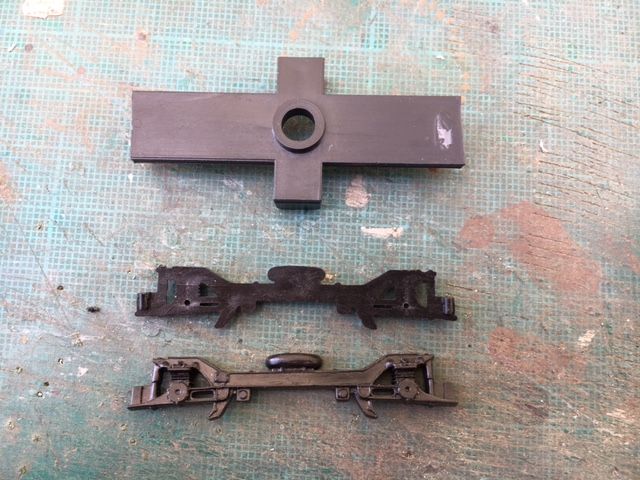
To rest my aching arms, I moved on to the bogies. These are provided as white metal sides with the standard chuncky plastic MTK mounting frames. I had bought a bag of plastic bogies cheap from somewhere a few years ago and this included a load of Class 508 style bogies. These had better and more consistent detail than the white metal sides and were modified to fit on the MTK mounting frames, which were themselves cut back to redued their "chunkiness". Wheel bearing holes were marked out and drilled. They run quite freely.
Cheers
Darius
-
3
-
-
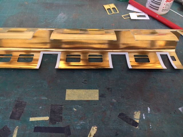
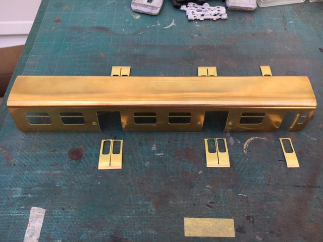
I have finally started this kit, which has been in the stash for a few years. Its the No Nonsense Kits (ex MTK) kit for a 4-car Class 508 EMU.
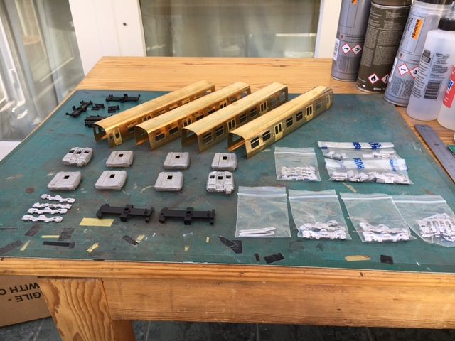
The bodyshells are in folded etched brass and the ends and other detail bits in white metal. The bodyshells are quite nice and a pre-folded to the correct(ish) profile with the curved tumblehome. The sliding doors are part of the sheet and so are almost flush with the bodysides, which is incorrect and looks odd.
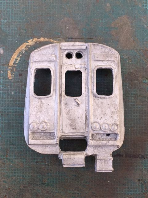
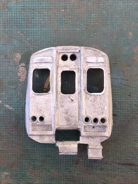
Much has been said on other posts om RMweb about the MTK white metal ends (and I have read a few of these as research for this project). Theydo still look better than a recently produced resin kit of this subject and so I decided to persevere with them and did a small amount of work to improve the "face". I cleaned up the part, widened the main windows with needle files and drilled out the lights.
Before:
After:
-
5
-
-
Hello,
I built the Southern liveried Bratchell Class 456. You need to scratch build the underfloor equipment and third rail pickup beams. I also added jumper cables to the cabs and led lights.
The kits are well designed and easy to build but you need to add details - especially to the cab fronts.
http://www.rmweb.co.uk/community/index.php?/topic/118946-southern-class-456/
Cheers
Darius
-
I do like that bridge. Is it kit or scratch built?
Cheers
Darius
-
Found it - it was on RMWeb - see post #83:-
http://www.rmweb.co.uk/community/index.php?/topic/67511-improving-the-Hornby-apt/page-4
Darius
-
First off im not sure if this is the correct place to post this so if then can an admin move it to the correct location please..
I have a few Hornby Eurostar sets that i want to run in 14 car lengths but the power car is just not up to this so i was woundering if anyone has converted the power car and if so what they did to improve this.
The only option i can think of is to run a power car at eachendand may be add a good amount of extra weight ??
All options considered
There is an article somewhere on the web (possibly on RMWeb) that I read a year or so ago where someone modified the power car with a central motor driving booth bogies via articulated driveshafts. I'll see if I can find it and post a link.
Darius


NNK/MTK Class 508
in Kitbuilding & Scratchbuilding
Posted
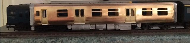
Driving coach chassis primed and painted satin black.
Body shells primed. Some minor filling and clean up required.
Cheers
Darius