
-

-
Popular Now
-
- 18 replies
- 108 views
-
- 325,954 replies
- 4,474,334 views
-
-


- Error Loading Block, Please Check The Settings
-
Upcoming Events
-
25 May 2024 Until 26 May 2024
0Welcome to our annual May Exhibition at Brockenhurst Village Hall
Open: Saturday – 10.00-17.00 Sunday – 10.00-16.30
Admission: Adults: £7.00 Accompanied children: Free
Refreshments & free parking. Full wheelchair access except the stage. The Hall is approx. 10 mins. walk from Brockenhurst station via gate from up-side car park. Our Exhibition will be showing visiting layouts, club layouts and members’ layouts. Visitors can see what we do and how we do it. We will be happy to discuss any modelling topics and answer any questions. As usual, there will be trade stands and displays.
Email: nfmrs@yahoo.com
Website: www.nfmrs.org
-
25 May 2024 09:00 Until 26 May 2024 15:30
0The Risborough & District Model Railway Club will be holding its annual RAILEX Model Railway Exhibition at the Stoke Mandeville Stadium, Stadium Approach, Aylesbury, Bucks, HP21 9PP, on Saturday 25th May (10:00 to 17:30) and Sunday 26th May 2024 (10:00 to 16:30). The exhibition will feature quality layouts, extensive trade support and demonstrations. There will be second hand sales, refreshments and some modelling displays. Entry for adults will be £11, children £5 (accompanied children free on Sunday), Families £25. For further details see the Railex website RAILEX 2024, the Risborough & District Model railway Club website R&DMRC and Facebook page R&DMRC Facebook
-
25 May 2024 09:00 Until 26 May 2024 15:00
0The Rother Valley Railway Supporters' Association announce their 2024 show, which includes tours of the RVR's new station site and the new turntable (ex-Hither Green), and a classic car display. See attached leaflet for full details.
Easy to reach by road, rail or bus (the new 1066 bus route from Hastings passes through the village).
See also the RVR website www.rvr.org.uk for more about the exciting project to rejoin Robertsbridge to Bodiam (KESR)
SAMREX 2024 poster v1 A4(1).docx
-
01 June 2024 Until 02 June 2024
3The Edinburgh and Lothians Miniature Railway Club (ELMRC) are hosting a new exhibition in Edinburgh at
George Watson's College
Colinton Road
Edinburgh
EH10 5EG
Sat 1st June 2024: 10am – 5pm
Sun 2nd June 2024: 10am – 5pm
Adults (16 years and over) – £8
Children (5 to 15, must be accompanied by an Adult) – £3
Under 5s – Free
Family (2 adults, 2 children) – £18
Tickets are available on the door, or can be pre-booked for a discount at https://www.ticketsource.co.uk/elmrc. Advance booking will close on Friday 31st May 2024.
The following Layouts have been confirmed:
Carr Street - Steam era goods depot - O - Renfrewshire MRC
United Mills - 1950s/60s Scottish Industrial - P4 - East of Scotland 4mm Group)
Cartom West - Modern Scotrail Terminus - 00 - Tam Gault
Dains Yard - 1970s Scottish Shunting Puzzle - 00 - Dundee MRC
Glendevon - 1950s Scottish Branch line - 00 - Edinburgh and Lothians MRC
Glenkiln Road - 1930s Southern Scottish Branch line - 00 - Glasgow & West of Scotland MRC
St Cuthbert - 1950s Southwest Scotland - 00 - Thistle Modelmakers
Tulloch Bridge - West Highland 2004-12 - 00 - Martin Stewart / Scottish Modellers
Balornock Goods - 1970s Glasgow yard - H0 - Kirkintilloch MRC
Eastern Steel & Iron - 1950s/60s North American Industrial - H0 - Stirling & Clackmannanshire District MRC
Levenbank - Scottish ECML Post privatisation - N - Glenrothes MRC
Nanjai Eki - Modern era Japan - N - Perth MRG
Wallacetoun Junction - 1990s Scottish station - N - Dundee MRC
The following traders have been confirmed:
Bernie Campbell
Douglas Blades
Franzi's Scenic Dioramas
KMS Railtech
Lathalmond Models
Rainbow railways
The following Societies and Demonstrations have been confirmed:
Model Electronic railway Group (MERG)
N Gauge Society
An up to date list of attendees is on the club's exhibition website at https://elmrc.org.uk/elmrc-exhibition/
-
01 June 2024
0Model Railway Exhibition Bronwydd Arms Village Hall Carmarthen SA33 6BE. Layouts of various Gauges, Demonstrations, Trade Support. Ample Free Parking. Good disability access. Presented by The West Wales Railway Modellers, incorporating The West Wales O gauge Group. Adults £5, Juniors £4 ( under 10 free). Family (2+2 ) £12. www.wwrm.co.uk
-
-
Recent Blog entries
-

- 401
entries - 933
comments - 289154
views
Recent Entries
 Latest Entry
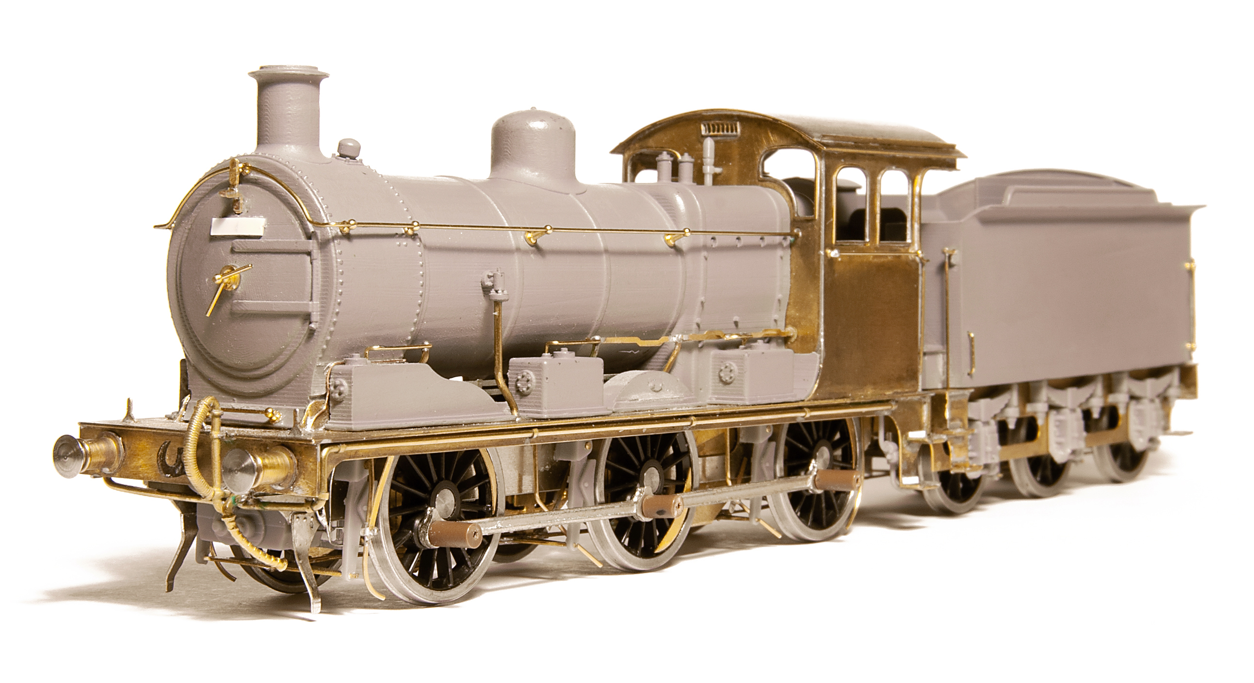
J17 - Kit finally available
So, after literally years of work, I have finally completed the J17 kit and it has been released by my friends at Brassmasters. The kit was officially first available at ExpoEM and some people have purchased one to build. It was a good feeling to see Jim Smith-Wright build the test etches, make such a nice job of it and apparently enjoy the process. (Yes, the push rods for the sanding gear were put on before Jim had the instructions telling him which way up they were meant to go - sorry Jim!)
This all started when I started trying to build a PDK Kit for a J17 to P4 gauge. I rapidly had to abandon the instructions and many of the parts because the compromises made were just too much for me. Before long I was replacing large parts of the kit and designing replacements both in etch metal and with 3D prints. This lead to a conversation with Brassmasters about the possibility of making my design available as a kit. Modelling the firebox/boiler/smokebox in 3D case was quite a learning experience as the model was probably an order of magnitude more complex than anything I'd done before. I decided that I wanted to try and use the etch metal to give the appropriate strength and thinness to the foot plate and cab sides. I originally 3D printed the entire tender in one go but decided quite earlier on to instead etch the chassis, a decision which I was very happy with.
If you want to purchase one take a look at the Brassmasters' website https://www.brassmasters.co.uk/ger_j17.htm
ExpoEM was proceeded by a large amount of 3D printing to provide some kits 'for stock' and putting the final touches to the instructions. The show itself was very enjoyable with a good selection of layouts and excellent trade. I can't think of anything else which would make a trip to Bracknell so worthwhile.
In the best tradition of 'no peace for the wicked' I'm now working on an extra etch for the cab front to allow an alternative 3D print to make a round-boilered J16 together with more parts for a Coronation.
David
- 401
-
- 173
entries - 1475
comments - 376786
views
Recent Entries
It was April 2019, almost five years ago to today’s date that I purchased a set of Hornby’s ex LMS non-corridor coaches. They were finished in BR Maroon livery, Hornby numbers R4689/90/91/91A. I like the detail, some nice wire handrails, individual roof ventilators and various steps. They have occasionally come out and trundled around the layout, often in the company of a Bachmann 2-6-4T or ex LMS Crab. They ran smoothly if somewhat noisily.
Hornby ex LMS non-corridor coaches in BR maroon in company with Bachmann Fairburn Tank.
Fast forward to 2024 and I have purchased a second set of ex LMS non-corridor coaches. This time they are finished in BR Crimson livery, Hornby numbers R4799/800/801/801A. I have included the Hornby coach numbers because my cameras (and on line advertisements) often mix up the crimson and maroon colours. I would say that ‘maroon’ is the muddy looking red.
Hornby ex LMS non-corridor coaches, crimson to the front, maroon to the back.
Now what else might provide suitable motive power? I have two Bachmann 4Fs, one with an Early Emblem and the other with a Late Crest. I thought they would be ideal for the crimson and maroon rakes respectively. I coupled the coaches up and set the two trains off, one behind the other around the layout.
Bachmann 4F with Late Crest on Hornby Maroon coaches
Bachmann 4F with Early Emblem on Hornby Crimson coaches
It was immediately obvious that the 4F with the late crest was struggling to haul its maroon coaches up one of my little inclines. Not only that but the crimson rake headed by the other 4F with the Early Emblem was running at almost twice the speed and was fast catching up with the maroon rake.
My first reaction was to service the 4Fs. A question for Bachmann, why do you have to disassemble the tender brake rodding to remove the four pin connector to uncouple the engine and remove the bodyshell – all to put a spot of oil on the motor bearing? Job done and just for good measure I swapped the engines around on the different rakes. No change, the train with the maroon coaches was still slowest. Manhandling the coaches to uncouple the engines hinted at the problem. The maroon coaches just did not run freely. My normal approach would be to use a ‘Truck Tuner’ to clean out the axle boxes. However the design of the Hornby bogies doesn’t provide enough space for inserting the tuner. I would have to use a different approach.
A comparison and the swap over of a wheel set from the newer crimson coaches to the maroon coaches had no effect. Whilst the wheels from the new crimson coaches had four holes compared to only two holes on the maroon coaches, this was not regarded as being relevant.
Studying the underside of the bogies suggested a problem with the ‘dummy’ brake shoes.
Upside down
I removed one wheel set at a time. Then using a small ‘snap off’ blade craft knife I gently pared some of the plastic from the inner face of the ‘dummy’ brake shoes. I attempted some before and after pictures but sadly my images of black plastic all look the same under artificial lighting.
Wheel set out showing offending brake shoes prior to fettling.
The result was immediate and very satisfying. I have attempted to demonstrate the problem and the solution in a YouTube video.The brake shoes were obviously rubbing, just like a real life situation where the locomotive was struggling to maintain the appropriate vacuum in the brake pipe.
The Hornby coaches are delicate and I took as much as half an hour per coach to free up all the wheel sets. I couldn’t decide whether it was the inner or outer brake shoes that were the problem. Obviously one or more tolerances are too tight. For good measure I inspected the latest crimson coaches and ended up fettling two wheel sets on two different coaches.
Individual coaches are joined with Hornby R8330 couplers whilst the ends of the rakes are fitted with Bachmann short straight couplers (36-061).
Hornby ex LMS non-corridor in Maroon Livery Hornby numbers R4689/90/91/91A
Hornby ex LMS non-corridor in Crimson Livery Hornby numbers R4799/800/801/801A
I think Hornby have some great coaches in their range and I have put together another video showing the two trains whilst they were chasing each other around the layout.
The Bachmann engines also perform much better with a little bit of tender and loving care (lubrication).- Read more...
-
- 0 comments
- 173
-

- 124
entries - 170
comments - 18981
views
Recent Entries
 Latest Entry
Time, gentlemen, please....
Got back yesterday evening from a trip to Lincs to watch the flat track racing, to find my good wife watching Eurovision.
Dear oh dear oh dear. What a crock. Still, Graham Norton liked the British entry.... given the blatantly politicised voting, which seems to get worse every year, the armed police around the venue and the rest of it, surely its time for this ludicrous travesty to be put out of its misery?
- Read more...
-
- 0 comments
- 124
-
-
Images


.thumb.jpg.60c53fcbcaa34017b05b8919d1a9e6d2.jpg)


-
-
Forum Statistics
-
Total Topics167.4k
-
Total Posts5.3m
-
-
Upcoming Events
-
025 May 2024
Until
26 May 2024
-
025 May 2024 09:00
Until
26 May 2024 15:30
-
-
Recent posts
-
13,169
Whacky Signs.
Well, I don't like it and can't use it, it just feels wrong. I am not in the game of decreeing what other people do, though, and accept that this has become accepted usage over the last 30 years or so, and nobody's going to listen to me. I have never had any problem making myself understood using he or she for individual people, and will continue to do so. -
20
Need - vs - Want
This is true. Tondu provided locos and stock for five branches, Porthcawl, Abergwynfi, Blaengarw, Nantymoel, and, until 1933, Gilfach Goch (reversal at Hendreforgan and it still wasn't an auto service), as well as work on the Bryncethin-Llanharan and OVE routes, and through work as far as Cardiff and Llandeilo Jc. The allocation varied but after the Gilfach Goch closure was usually around 50 locos, but it would be far too simplistic to suggest that each branch had 10 locos, or even 5, to handle it's work. That said, the Tondu Valleys branches were probably the most intensely worked single track network in the world, being close to capacity except for the few hours between half past midnight and about 5am when nothing ran and the boxes were closed (nothing ran on Sundays either). I think it is probably reasonable to say that another 5 engines would have had to have been found from somewhere had there ever been a branch to Cwmdimbath, but that is not the same as saying that any of those engines would appear there on any working day, never mind all of them. I am considering the Taff A and Rhymney R as eventually fulfilling this role, engines close to the ends of their working lives that other sheds might be willing to release, but any more than this would be pushing it I feel. 44xx? All gone from 1953, and less evidence than for 3100, the shed's Collett 1938 large prairie, 3150 rebuild, no.4 boiler, 5'3" wheels, 220psi boiler pressure, bit of a thug, used on the Porthcawl-Cardiff 'residential' commuter train becasue of it's ability to get away from the main line stops rapidly and keep clear of other traffic. There is a photo of this on Google in 1951 at Abergwynfi, good enough for me and a kitbash is in progress, albeit at plate tectonic pace... I keep lobbying for an 1854 or a 2721 half-cab pannier, and have done well over the last decade or so with wishlisting, so my fingers are crossed, perhaps from Accurascale using their new pannier chassis. In practice, though, not all the locos worked all the branches all the time. 57xx/8750s did, as did 1854/2721s before them, I have seen photos of 94xx on Abergwynfi and Nantymoel passenger jobs (they were considered to be passenger engines at Tondu for some reason), 4575s worked on the Abergwynfi and Nantymoel auto trains but Blaengarw was closed to passenger just before they arrived, TTBOMK the 44xx were strictly Porthcawl engines, 56xx were only used on the Abergwynfi branch, and 42xx were used on Abergwynfi and Blaengarw coal trains. A real Cwmdimbath might well have been wall-to-wall 57xx/8750 prior to 1953 and those engines pluse 4575s on autos afterwards. But not on my layout. Cwmdimbath is likely to be considered the least important of the branches surviving into BR days. The 'big towns' were Maesteg, on the Abergwynfi Branch, and Ogmore Vale on the Nantymoel (closed to passengers 1958). My mum's definition of towns and cities, as valid as any I contend, was that a town had a Woolworths and a city had a Woolworths and a Marks & Spencer; Maesteg and Ogmore Vale had Woolworths'. Cwmdimbath so far has a pub, a Post Office, a cafe, and 17 houses, even Gilfach Goch could beat that. The branch has remained open mostly because the extra cost of providing a passenger service on a line that has to be kept open for the colliery is not high over such a short distance, and the road access is steep and narrow. So locos and stock provided to it by Tondu will be the bottom of the heap, locos that are not in the best condition as would be needed for Abergwynfi, the bottom link stuff. This plays both to the possibility of Rule 1 Taff A & Rhymney R transfers and to locos appearing having missed their booked job for some fault or other now repaired and taking on what was originally a 57xx turn. I have decided arbitrarily that the steepness of the branch needs 56xx on the colliery trip though, and that if a 42xx works it it is not allowed on to the exchange loop, which complicates the shunting. -
450
Cavalex - New Class 60
What about having a timer when stopped for the headlight to go out? Stopped at a signal for a short period of time headlight would remain on. Into a loop for some time and let's say after 3 minutes the headlight would go out. Timers possible on functions I believe, certainly seen the options in the Lokprogrammer. Change of CV could change the time so to suit end user's preference, ie could change to a shorter time if desired or a much longer time if function not desired. -
9,764
More Pre-Grouping Wagons in 4mm - the D299 appreciation thread.
Bill Firstly, and most importantly, I am glad you are recovering. When I contemplated starting Meon Valley Models and turning an interest into a business, I did look at your business model but decided that the only way it was going to work for me (with full time job and three teenage kids) was batch production. That model has been further refined, as anyone who has bought one of my wagons recently may have noticed, with labels now listing the component parts. This is to ensure that I pick the right parts for each kit as batch production does have a downside in that holding and managing stock becomes much more challenging! In my case, all items are available all the time with a new batch run whenever stocks are getting low. Reading between the lines on the Cambrian Models web site, they seem to take the same approach albeit their stock coverage seems to be lower - I think there have only been two occasions when I haven't had stock on hand. Ultimately, you have to do what what you are going to enjoy most and which gives you the best quality of life (why weren't we taught about that in careers sessions at school?!). Whatever you decide, your contribution to the hobby has been, and continues to be, immense. Long may that continue. Andy -
72
Newbie advice please
Not quite sure what the OP is after, but building on Phil's latest sketch, one possibility might be a (level!) double track circuit with a fiddle yard behind the backscene in the area marked "branch line climbing" and a purely scenic run along the lower boards (marked "fiddle yard", with two double-to-single junctions leading to the single track line through Llanuwchllyn. Perhaps making a feature of one of the junctions by having it flying or burrowing, using the bottom and right hand boards, with the other one on the narrow board to the left Sort of like this (with no attempt to draw to scale):
-
-
Active trade topics
-


